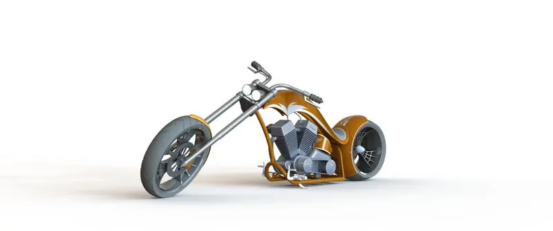
Photo Realistic Rendering
PROJECT REPORT
TITLE OF THE PROJECT :-American chopper
OBJECTIVE:-
*The objective of this project is used for create a model of different parts of the chopper useing solidwork software.
*To assemble the each of one part.
*To create a model and photoview 360 useing for better photorealistic rendering .
INTRODUCTION:-
*American chopper owns paul teutul sr. he design this model .
*chopper is a type of custom motorcycle
*The first chopper built in America and tended to be based on Harley Davidson motorcycles.
*Purpose of this project to create an design and assemble and rendering solidwork and solidwork visualize.
*its use to re edting models and performance oriented chopper and more about achieving a certain look.
PART MODELING:- Part modeling is a create the sketch and solid feature apply is call part modeling and modify part through direct and intuitive graphical manipulatiPon
PARTS:-
The following parts of the chopper are modeled in solidwork and assembled together.
1.Transmission belt.
2.Kick stand.
3.Front fender.
4.Rear fender.
5.Oil tank.
6.Chain.
7.Pedal.
8.Front wheel.
9.Rear wheel.
10.Engine.
11.Front fork.
12.Chassis.
13.Gas tank.
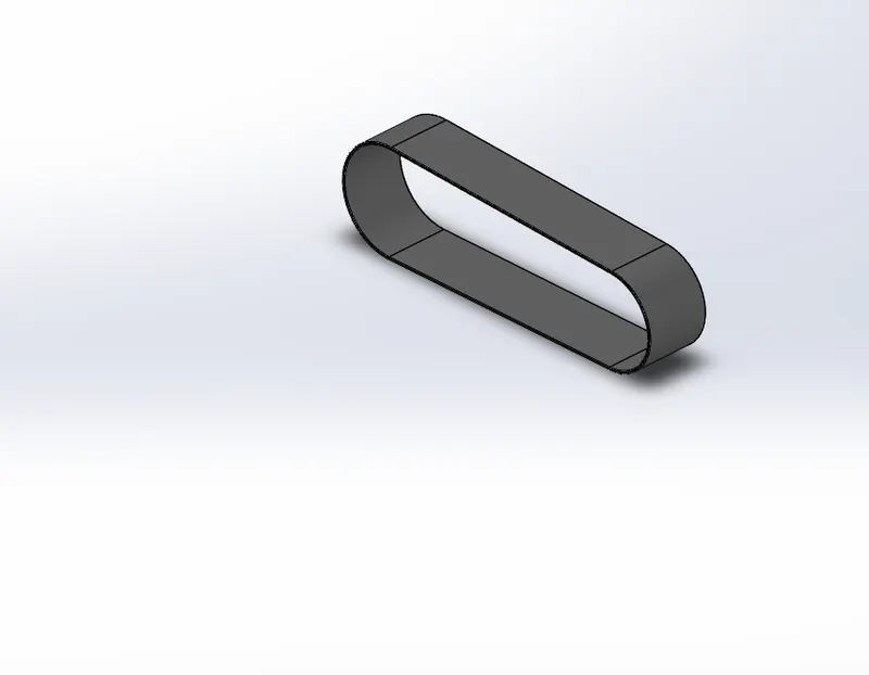
1.Transmission belt:-
*The transmission belt motorcycles part its used to transmit the power
From the engine to the gearbox.
*
*Create this transmission belt used features and tool are used
1.Sketch
2.Offset
3.Fillet
4.Appearances
*Sketch
Sketch is a two dimensional representation of the model with respect to the plane and view from the outside of the model in solidwork there are different sketch option available in solidwork .line,arcs,and splines,circles,rectangle this entities are available in solidwork.
*Offset
Offset one or more sketch entities , selected model edges, or model faces by a specified distance . example, you can offset sketch entities such as splines or arcs ,sets of model edges ,and finite lines,arcs,and splines
*Extrude
Convert 2d sketch to 3d model.
*Fillet
Fillet/round creates a rounded internal or external face any part faces fillet all edges.
*Appearances
Model colours to used the each of colours.
*how to create a model of transmission belt.
First solidwork software opened and than clicked a new part file and create a new model
Afterthat plane name are edit example,
Front plane – front plane transmission belt
Top plane – top plane transmission belt
Right plane – right plane transmission belt
Than,the front plane is selected to sketch
The 2d sketch is created in the front plane and dimension ,relations are given to the sketch to fully define a sketch .
After this process the sketch is closed than the extrude command is used to convert 2d to 3d than fillet apply and than saved the model is transmission belt.
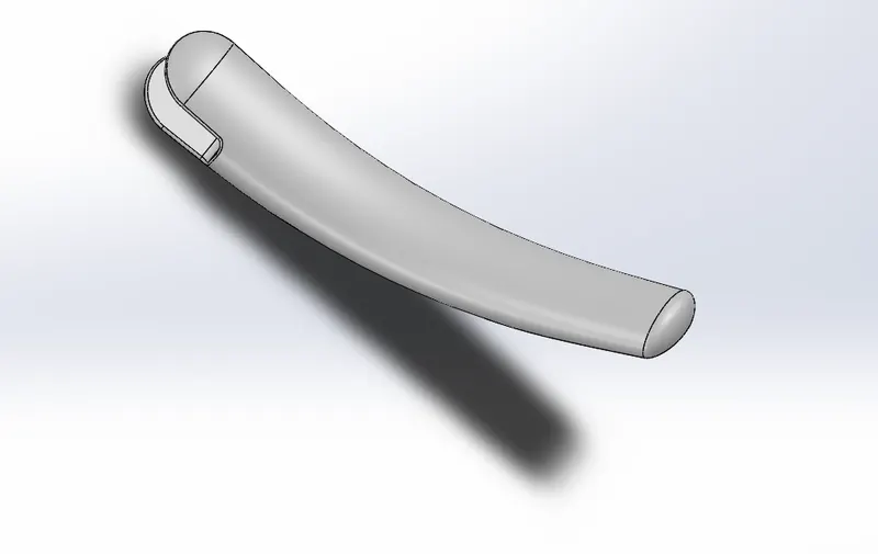
2.Kickstand
The kickstand is knows as side stand of chopper model.
Sketch
Loft
Dome
Extrude boss
Extrude cut
Fillet
Split
Appearances
*Loft
The loft is a solidwork feature tools its used to interpolating surfaces between various cross section of a model .these cross-section can be sketch ,faces ,or edges in the loft interface ,these cross-section are consider loft base profile
*Dome
Solidwork provides a tool called dome that you can create domes on 3d parts are shapes . selected one or more planer and non planer faces. You can apply domes to faces whose centroid lies outside the faces. The allows you to apply domes to irregularly shaped contours
*Extrude boss
An extruded boss/base feature will allow you to take a 2d sketch and add thickness to it in the third dimesion
3.Front fender
Fender is a body that frames the wheel well .its primary purpose is to prevent sand ,mud, rocks, and other road spray from being thrown into the air by the rotating tyre.
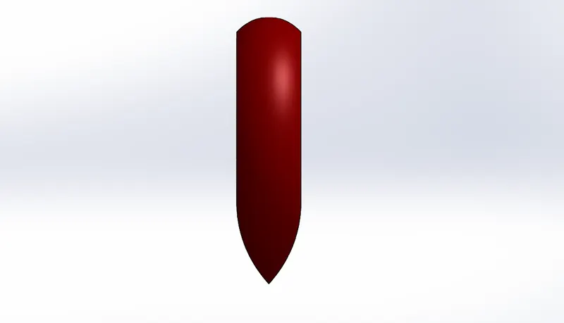
Features used to create front fender
*sketch
*offset entities
*revolve
*dynamic mirror
*split
*appearances
Revolve
To create a revolve feature create a sketch that contains one or more profile and a centerline,line,or edge to use as the axis around which the feature revolves
Dynamic mirror
Dynamic mirror is a solidwork tool its important they are mirrored about the preselected sketch entity.
4.REAR FENDER
Fender is a frames the wheel well its primary use is to prevent sand,rocks,liquids,and other road spray from being thrown into the air by the rotating tyre.
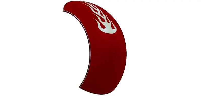
Features used to create rear fender
*sketch
*offset entities
*trim entities
*revolve
*appearances
Trim entities
Select the trim type based on the entities you want to trim or extend
All trim types are available with 2d sketchs and 2d sketches on 3d planes you can use any of the following trim option -power trim
Appearances
An appearances defines the visual properties of a model,including color and texture .appearances do not affect physical properties which are defined by materials. every material is assigned a default appearance that emulates the look of the material.
5.OIL TANK
Stores the oil for lubrication and cooling purposes.
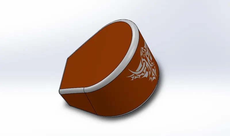
Features used to create oil tank
*sketch
*boss extrude
*combine
*fillet
*shell
*appearances
6.CHAIN
Chain drive is used for transmission of mechanical power,in this case the power from the engine to the wheels of a vehicle.
Chain drive design was a lengthy process as it required repetition of various commands but the curve driven pattern and mirror commands in solidwork came handy in this case.
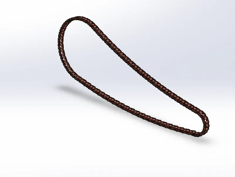
Features used to create chain
*sketch
*trim
*fillet
*blocks
*extrude
*patterns
*appearances
PATTERNS
The curve driven patterns tool allows you to create patterns alongs a planar or 3d curve . you can base pattern on an open curve or on a closed curve,such as a cricle .in the part curve driven patterns used
7.PADEL
Padel used for placing the foot,applying brakes and shiffing the gear in a motorcycle.
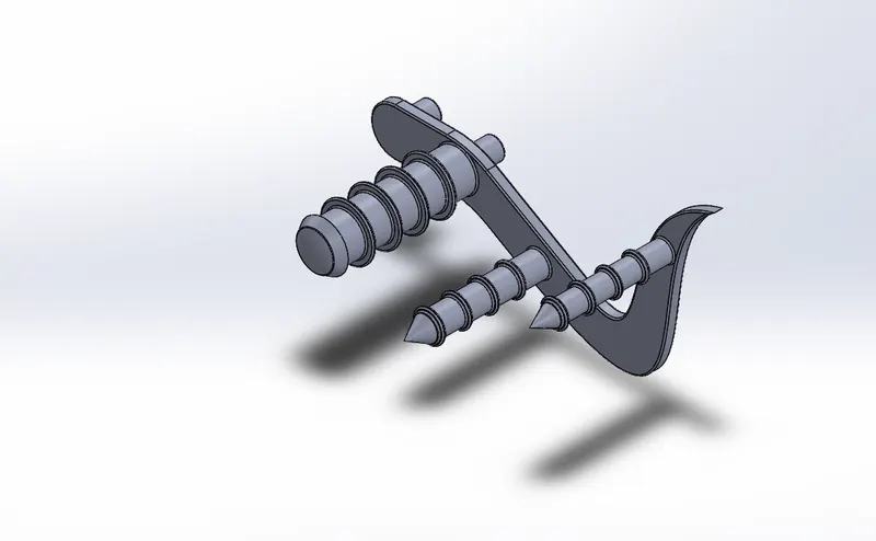
Features uesd to create padal
*sketch
*extrude
*fillet
*liner pattens
*dome
*chamfer
*appearances
Linear patterns
Linear patterns is also more like a cricular pattern.the features/bodies are patterned linearly. Patterns is a kind tool like array available in autocad
CHAMFER
A cut on the edge or cornerof something that makes it slope slightly rather than being perfectly square.
8.FRONT WHEEL
The front wheel consists of the unique spider web shaped rims tyre brake rotor and caliper.
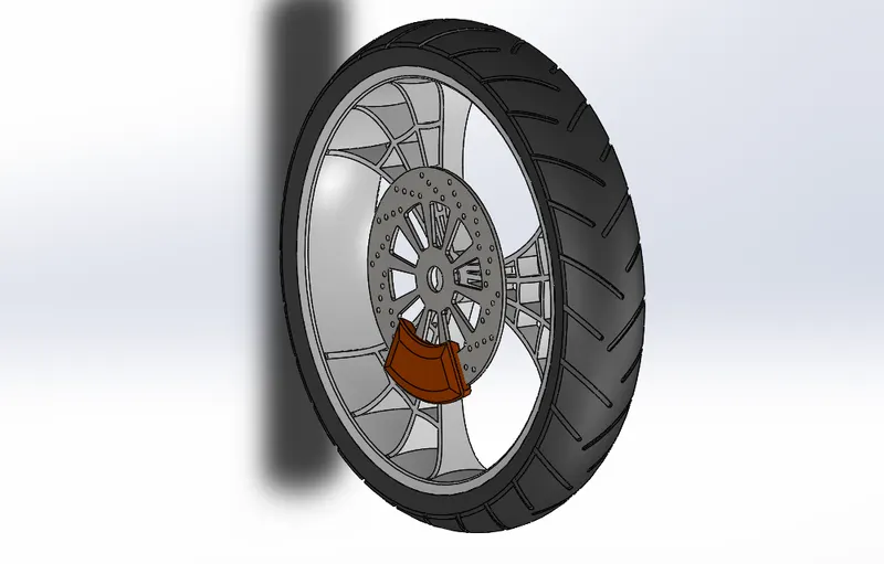
Feature used to create front wheel
*sketch
*revolve
*trim
*convert entrities
*boos extrude
*base extrude
*revolve cut
*linear pattern
*chamfer
*fillet
*cut extrude
*circular pattern
*appearance
Circular pattern
Circular pattern is used to create a pattern of the sporks and the pattern available in the tyre . also it is used to create holes in the discs of the front wheel . the parent bodies/features are used to create a different number of instances required to create the pattern circulary.
9.REAR WHEEL
The wider but stockier rear wheel consists of the unique spider web shaped rims tyre and brake rotor,caliper and sprocket. A circular object that revolves on an axis to the axis .the chain is connected between the engine and the rear wheel.chain is a positive drive compared to the belt it will be more efficient and losses in the chain will be less comparatively
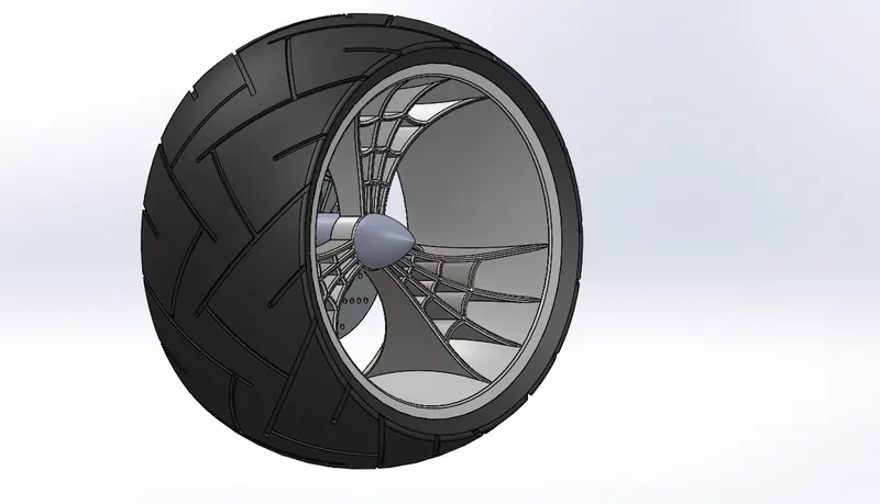
Features used to create rear wheel
*sketch
*revolve
*trim
*fillet
*planes
*revolve cut
*liner pattern
*chamfer
*extrude cut
*circular pattern
*appeaeances
10.FRONT FORK
The fornt fork connects the front wheel and axle to its frame typically via a yoke also knows as a triple clamp which consists of an upper yoke joined to a lower yoke via steering head creating the steering axis most motorcycles today use the shocks absorber whith internal coil spring they allow the front wheel to react to imperfection in the road while isolating the rest of the motorcycle form that motion
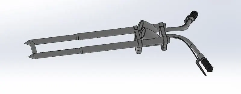
Feature used to create front fork
*sketch
*extrude
*trim
*revolve
*split
*plane
*convet entities
*move/copy
*dome
*mirror
*combine
*curve
*sweep
*appearance
Sweep
Sweep create a shape by moving a 2d sketch profile along a 2d or 3d sketch path.
Move/copy
Move /copy body is used to move /copy the body form one place to other places in the fork
Project curve
Project curve is the kind of 3d curve which is projected on the basis of the two different 2d sketches
Mirror
Create and other part mirror than the part manually combined.
11.CHASSIS
Chassis/frame is the motorcycles core structure .it support the engine provides a location for the steering and supports the rear end and the rider along with any passenger or luggage the fuel tank is attached to the frame.
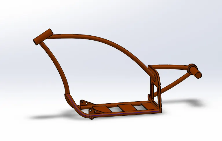
Features used to create chassis
*sketch
*offset
*convert entities
*project curve
*trim
*plane
*sweep
*split
*revolve
*extrude cut
*fillet
*combine
*appearance
12.ENGINE
An engine power a motorcycle . engine is a prime mover for the bike . the engine convert a chemical energy into the heat energy and than heat energy converted mechanical work.the mechanical work in the engine is rotational motion this rorational motion converted to the wheel with the use of the chain and sprocket
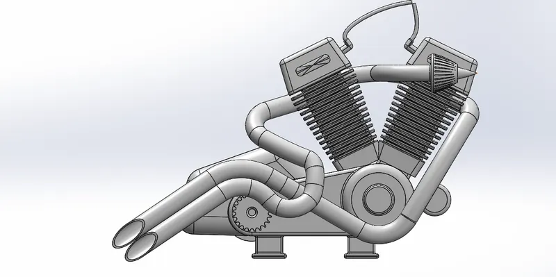
Features used to create engine
*sketch
*convert entities
*trim
*revolve
*boss extrude
*extrude cut
*offset
*dome
* fillet
* project curve
*composite curve
*sweep
*mirror
*circular pattern
*split
13.GAS TANK
Unlike other part where solid modelling was used gas tank was majorly designed using surface modelling, gas tanks are used to store the gas . to give the gas to the engine whenever its required
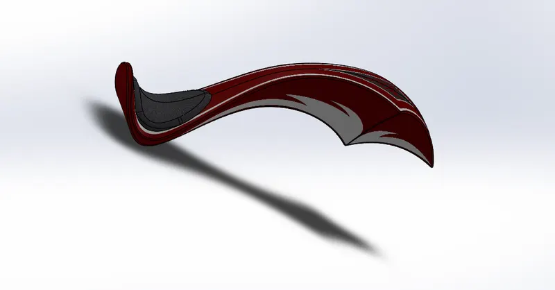
Features used to create gas tank
*sketch
*trim
*project curve
*convert entities
*sweep
*surface trim
*surface knit
*sweep cut
*fillet
*appearance
LOFT SURFACE
Loft surface are surfaces generated by multiple 3d curves or existing edges creating a smooth tangency between the selected curves.
SURFACE TRIM
Primarily used to cut away material from a surface and provides two modes standard and mutual.
SURFACE KNIT
Surface knit is used to knit the two free edge/open edge of the surfaces together.also it reduces the gap between the two edges of the surface.
ASSEMBLY OF CHOPPER
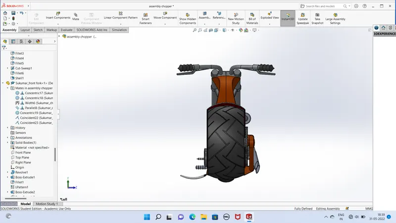
Assembled the parts of the chopper using relation,standard mates(coincident,parallel,tangent,perpendicular,etc) advanced mates (symmetric,width,angle etc.) and mirroring plane orientation /alignment was taken care of while performing the mating.
Some parts like kickstand and front fork needed a limiting angle which was set while applying mates . some parts had to be edited to avoid any bad geometry from showing up in the assembly.
REAR VIEW OF THE ASSEMBLY
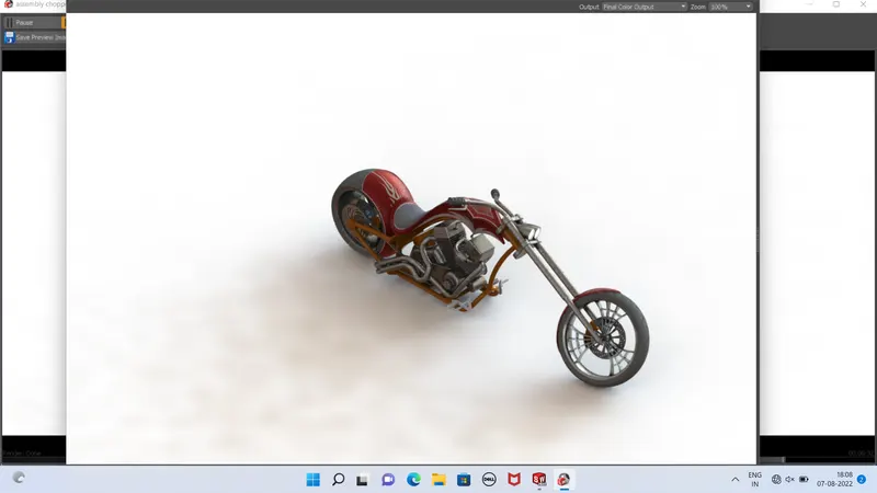
ISOMETRIC VIEW OF THE ASSEMBLY
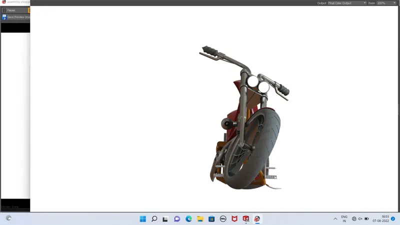
FRONT VIEW OF THE ASSEMBLY
RENDERING
Rendering the model was done using photoview 360 in solidworks
Decal were applied in the case of oil tank ,gas tank and rear fender during the final model rendering stage.
PHOTOVIEW 360(SOLIDWORKS ADD-IN)
Rendering using photoview 360 involved setting the scene,environment,camera,perspective and light adjusting various parameters
CONCLUSION
Thus,the exterior parts of an American chopper were designed modelled and assembled using solidworks 2020 and 2021 and 2022 .