Photo Realistic Rendering
MODELLING AND RENDERING OF AMERICAN CHOPPER
OBJECTIVE:
-To create modelling and photo realistic rendering of American chopper by using solidworks.
-To assemble different parts of Chopper under the assembly environment.
EXECUTION:
STEPS FOR DESIGN:
-open a new file
-Selection of plane (X,Y,Z Axis)
-sketch as per dimension in 2D
-Surface modelling or solid modelling (boss exclude)
-Fillet or chamfer
-Give apperance(coler,decals)
-save the design or model
MODELLING:
THE CHOPPER CONSIST OF THE FOLLOWING PART’S
1.chassis
2.Engine
3.Front fork
4.Pedal
5.Chain
6.Oil tank
7.Gas tank
8.Transmission belt
9.front fender
10.Rear fender
11.Front wheel
12.Rear wheel
13.Kick stand
All the parts are designed separately and finally assembled together to get the final American chopper.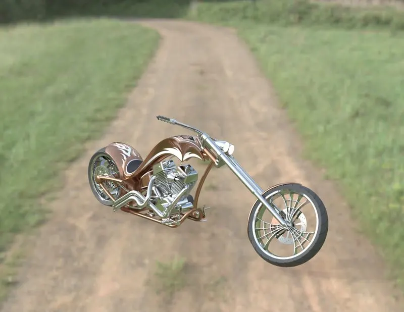
Week1:
PARTS:
1.Transmisson belt
2.kick stand
3.fender
Command’s used:
-2d sketch
-Lines and circles
-Extrude
-revolve
-Dome
-Fillet
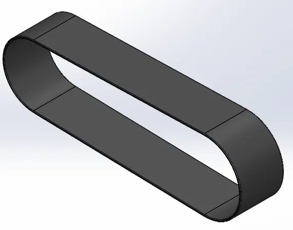
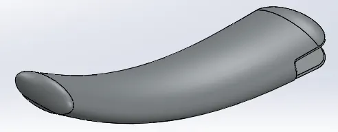
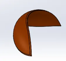
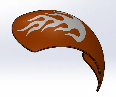
The above following commands are used to design to make the week 1 parts.and the dimensions and instructions are followed by the week 1 video. Most of the solid modelling tools are used to design the above parts.
Week2:
PARTS:4.Oil tank 5.Chain 6.Pedal
Command’s used:
-2d sketch
-Sweep
-Revolve
-splines
-Trim
-Extrude cut
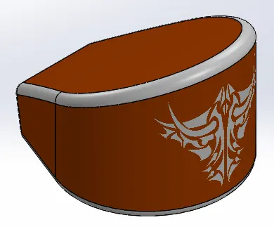
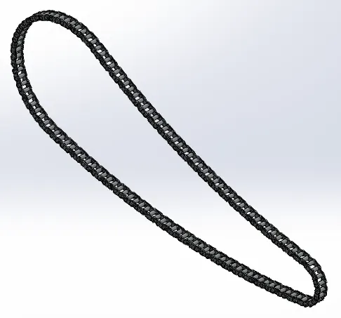
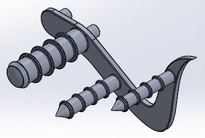
The oil tank is used as a reservoir to meet the oil requirements of the engine and to lubricate the parts. It is hollow in nature.
Week3:
PARTS:7.Front wheel
Command’s used:
-2d sketch
-Sweep
-Revolve cut
-Circular pattern
-combine
-Extrude cut
-Revolve
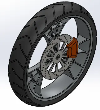
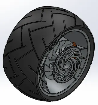
Rear wheel is situated at rear portion of chassis. The rear wheel carries the large sprocket and disc. The power is transmitted to rear wheel from the gearbox through the chain.
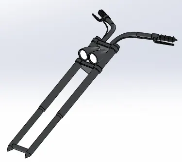
Front fork connects a motorcycle's front wheel and axle to its frame, typically via a yoke, also known as a triple clamp, which consists of an upper yoke joined to a lower yoke via a steering stem, a shaft that runs through the steering head, creating the steering axis. Most forks incorporate the front suspension and front brake and allow the front wheel to rotate about the steering axis so that the bike may be steered.
Week5:
PARTS: 10.Chassis 11.engine
Command’s used:
-Sweep
-Revolve
-Extrude
-Dome
-Projected curve
-Split
-Mirror
In the chassis model most of the surface modelling tool like sweep and projected curves are used to give the better finish.

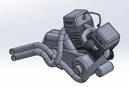
The projected curves are used to make the engine exhaust, most of the solid modelling features are used to finish the engine.
The above following commands are used to design to make the week 4 parts.and the dimensions and instructions are followed by the week 4 video
Week6:
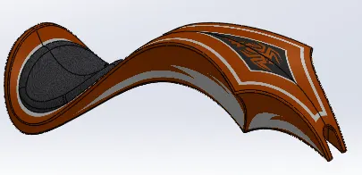
PARTS: 12.Gas tank
Command’s used:
-Surface loft
-Surface Sweep
-Boundary surface
-Revolve
-Extrude
-Knit surface
-Projected curve
Composite curve - The composite curve tool provides the ability to create composite curves by combining two curves. The composite curve is the combination of the two projected curves.
ASSEMBLY
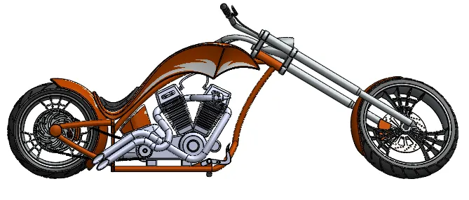
Assembly is done in the assembly environment by inserting all the modeled parts of the chopper using insert part option.
Parts of the chopper are fixed in the assembly environment by giving possible mate conditions or by fixing the planes.
You can build complex assemblies consisting of many components, which can be parts or other assemblies, called subassemblies. For most operations, the behavior of components is the same for both types.
Adding a component to an assembly creates a link between the assembly and the component. When SOLIDWORKS opens the assembly, it finds the component file to show it in the assembly. Changes in the component are automatically reflected in the assembly.
MATES
Mates create geometric relationships between assembly components. As you add mates, you define the allowable directions of linear or rotational motion of the components. You can move a component within its degrees of freedom, visualizing the assembly's behavior.
TYPES OF MATES
The various types of mates available in Solidworks are:-
- Standard Mates - Angles, Coincident, Concentric, Distance, Lock Parallel, Perpendicular, Tangent mates.
- Advanced Mates - Limit, Linear/Linear coupler, Path, Symmetry, Width mates.
- Mechanical Mates - Cam-follower, Gear, Hinge, Rack and Pinion, Screw, and Universal joint mates.
SIDE VIEW
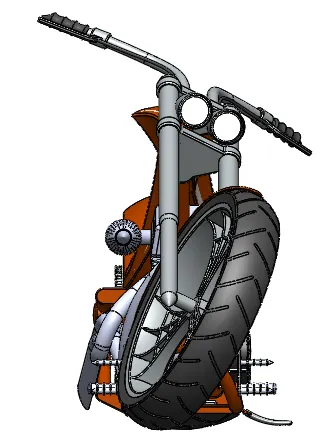
FRONT VIEW
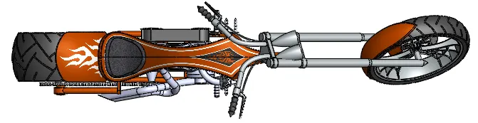
TOP VIEW
BACK VIEW
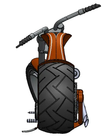
ISOMETRIC VIEW
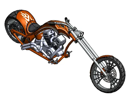
CAMERA VIEW
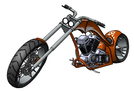
PHOTOREALISTIC RENDERING OF CHOPPER
Rendering is the process of creating realistic images of the Photorealistic model with the environment. Rendering has been done in two ways in solidworks. The following are the two ways:-
1. Photoview 360
2. Solidworks Visualize
In the photorealistic model, some of the mate conditions and positions are changed to render realistic models. Then the photorealistic model is rendered into realistic images with different views.
Conclusion
- All the exterior parts of the chopper are modeled successfully under SolidWorks modeling environment.
- All the parts are inserted into the assembly environment and the chopper is successfully assembled.
- The photorealistic image is successfully rendered with the use of the Photoview 360 & Solidworks visualize.