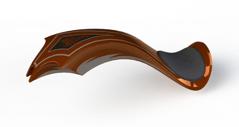
Photo Realistic Rendering
Objective
Modeling the chopper (American style motorcycle) design using SOLIDWORKS software relying on course instructions.
Going through the various challenges and project reports associated with the learning path experience.
Introduction
Modeling the said chopper provided a great opportunity for exercising various software tools and modeling techniques.
While following course instructions was a great opportunity for exercise, going through the various challenges was also an opportunity for further practice; offering instructor evaluation and feedback.
This project report provides an overview of the incorporated design approach, as well as design process description.
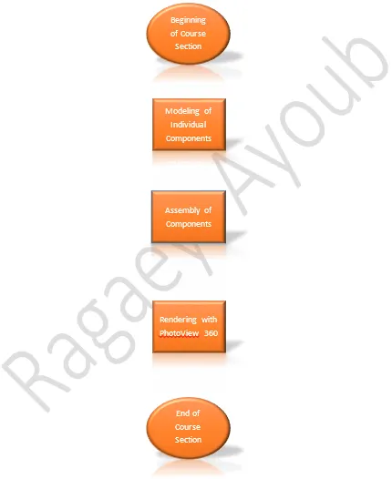
Beginning of Course Section
Modeling of said chopper is a part of the multi-subject course, hence, it's considered a section of that course; the first one that is.
Modeling of Individual Components
A detailed walkthrough of the modeling process of each of the chopper components; covering the required design tools and features, as well as appropriate approaches.
Also, the component materials (appearances) that would be required later on in other stages (Rendering with PhotoView 360) are applied in this stage of modeling.
Assembly of Components
Assembling the various chopper components modelled; covering browsing for them, their insertion into the software, relations to one another (mates), assembly-related tools and features, as well as the required assembly-scope adjustments related to compatibility among modelled assembly components.
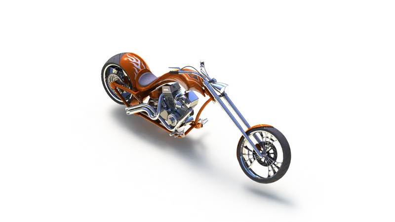
Rendering with PhotoView 360
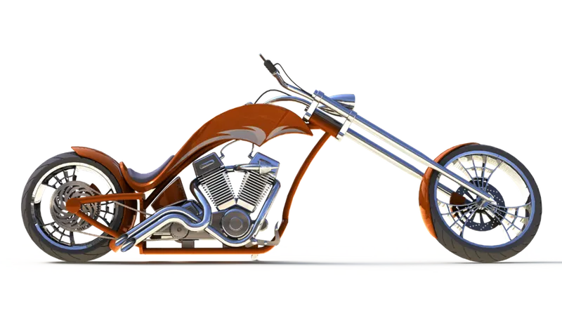
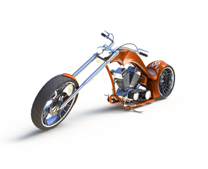
Detailed walkthrough of PhotoView 360 add-in activation, different rendering tools (e.g., the Preview Window command), setting up the model in the environment, as well as applying decals to the modelled components.
Also, appearance adjustments (e.g., adjusting colors, and editing applied materials) related to rendering setup, as well as the incorporation of display states and configurations were discussed in detail.
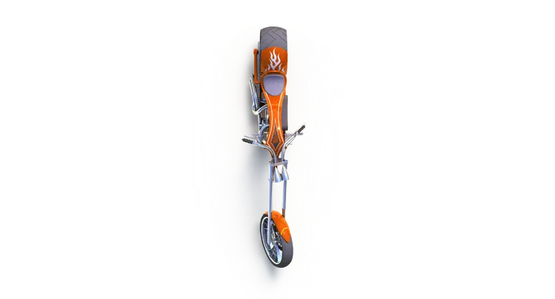
A high-quality render requires careful composition of the scene, which includes selecting proper rendering views, adding required cameras and lights, scene selection, as well as the appropriate rendering options (e.g., gamma level).
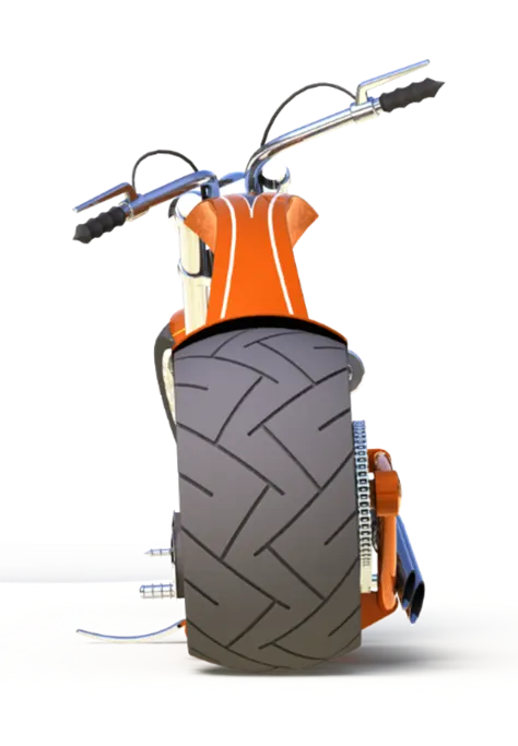
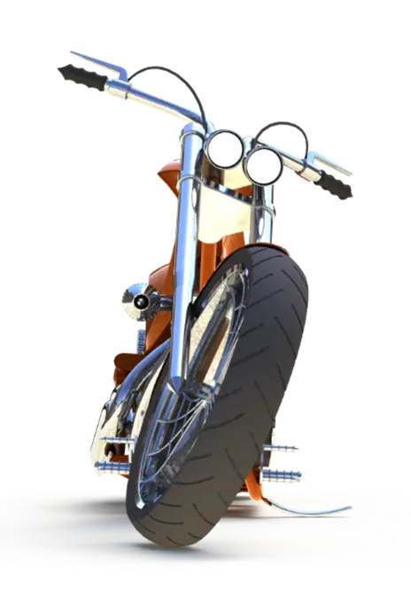
End of Course Section
The end of the modeling and rendering portion of the course, and the beginning of the next one; covering new topics, such as sketching.
Description
This section provides a summarized explanation of the design tools and features associated with each model component.
The modeling process of all model components incorporated application of materials correspondent to each component, or component portions where required through the appearance tab of the feature manager tree.
Transmission Belt
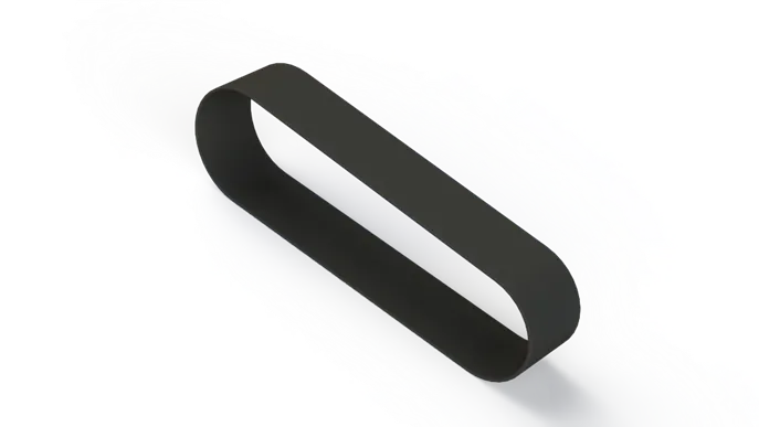
Modeling of the transmission belt component incorporated two basic design features, which were an extruded body (Boss-Extrude), and an edge fillet feature.
Kickstand
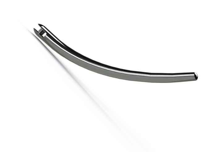
Modeling of the kickstand component incorporated additional design features, such as a loft feature for obtaining the main body, dome features for the tips, as well as the split feature for the flat portion of the component.
Front Fender
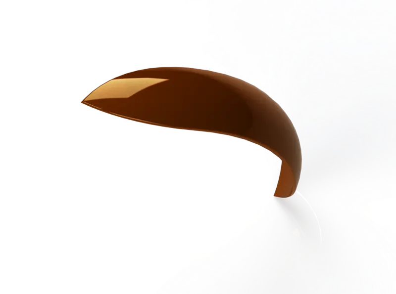
Modeling of the front fender component incorporated one additional design feature that was required for obtaining the required rounded geometry, which was a revolve feature, revolving about the front wheel center.
The remaining features were of those mentioned earlier, required for cuts and aesthetics.
Rear Fender
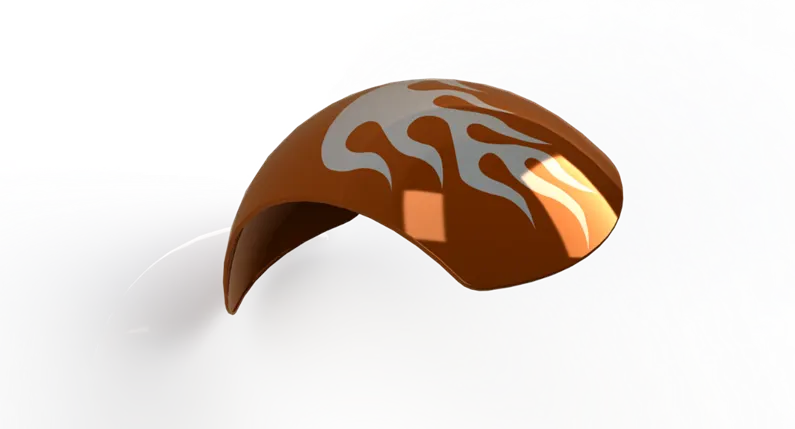
Modeling of the rear fender component incorporated one additional design feature that was required for obtaining the required intruding inner surface, which was the shell feature.
Also, the required decal was applied to the component outer surface using label-type mapping.
Chain
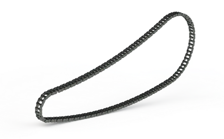
Modeling of the chain component incorporated additional design features, such as the curved pattern (CrvPattern) feature for obtaining the required component (chain) profile, as well as inserting sketch blocks required for the chain links profiles.
Oil Tank
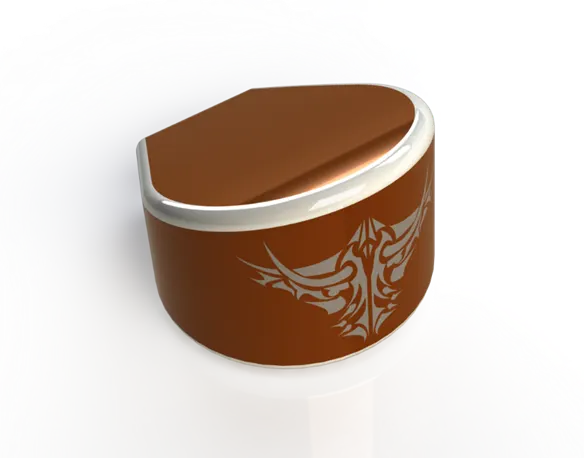
Modeling of the oil tank component incorporated no additional design features; being of a simple and straightforward geometry, previously mentioned features were adequate for modeling it.
Also, the required decal was applied to the component outer surface using projection-type mapping.
Pedal
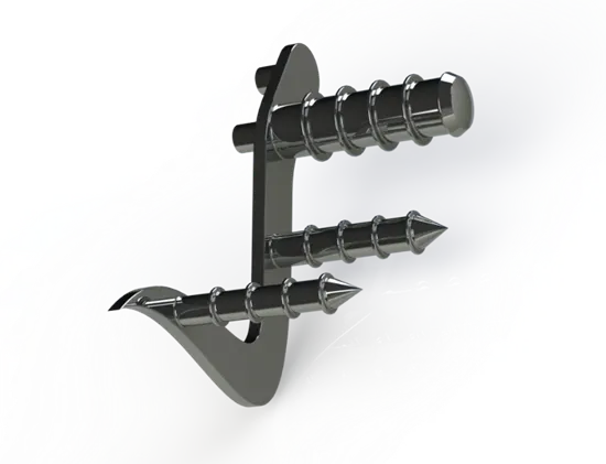
Modeling of the pedal component incorporated two additional design features, which were the chamfer feature for obtaining the tipped rod ends, as well as the linear pattern feature (LPattern) for the required number of protruding cylindrical supports.
Also, the mirror feature was incorporated for obtaining the left-hand pedal component (PedalLH), which was created as a separate dependent component (on the right-side one).
Front Wheel
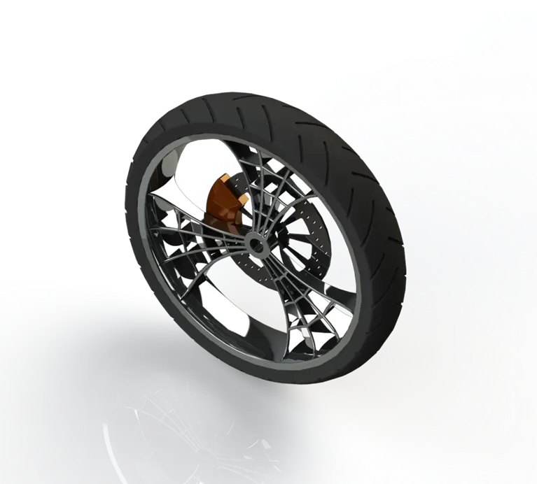
Modeling of the front wheel component incorporated additional design features, such as the revolved cut (Cut-Revolve) feature for obtaining the required outer rim surface curvature, as well as the circular pattern (CirPattern) feature for the required radial geometries.
Rear Wheel
Modeling of the rear wheel component incorporated no additional design features; being of similar geometry to the front wheel component, previously mentioned features were adequate for modeling it.
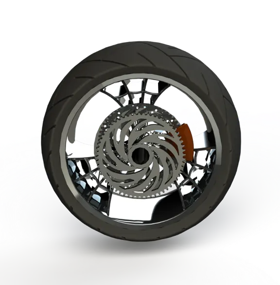
Front Fork
Modeling of the front fork component incorporated additional features, such as the surface moving (Body Move/Copy)) feature for obtaining the required position of the left-hand headlight, as well as curve projection (Projected Curve) and swept body (Sweep) features for the required handle geometry.
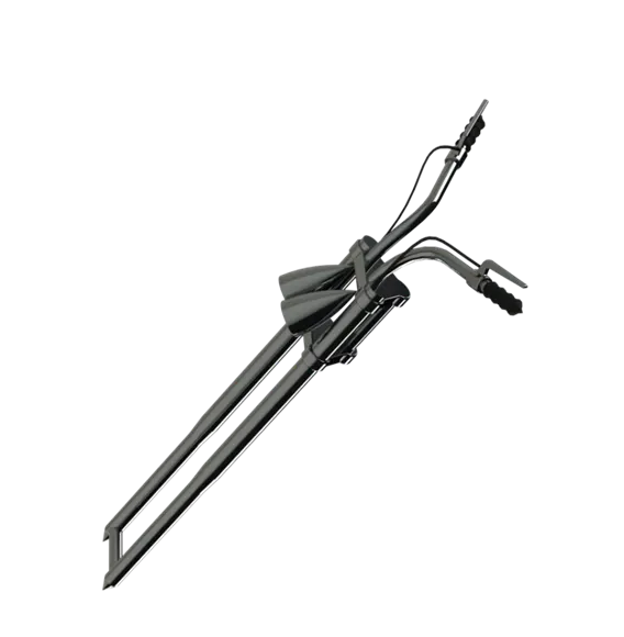
Chassis
Modeling of the chassis component incorporated one additional design feature that were required for maintaining the required number of solid bodies within the component, which was the combine features used at several locations within the chassis model.
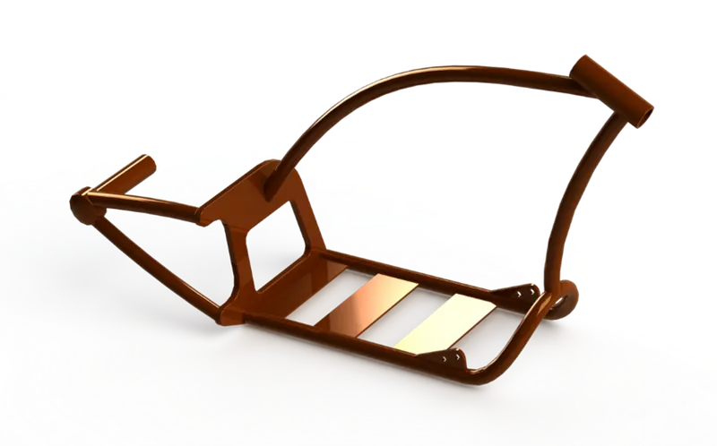
Engine
Modeling of the engine component incorporated no additional design features; having a geometry that required no further features to be modelled than those previously mentioned ones.
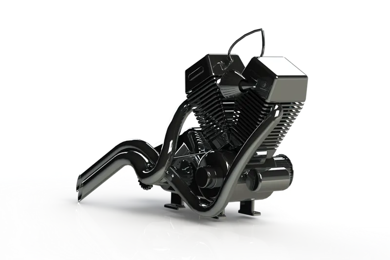
Fuel Tank
Modeling of the fuel tank component incorporated additional surfacing design features, such as the swept cut (Cut-Sweep) feature for obtaining the groove required for accommodating the chassis member (tube) underneath the tank, as well as the surface knitting features for maintaining the required number of solid bodies within the component.
Also, the required decals were applied to the component outer surface using projection-type mapping (all three of them).