Photo Realistic Rendering
Modelling, Assembly and Rendering of American Chopper
OBJECTIVE:
The objective of this project is to model the parts, assembly of an American Chopper using Solidworks Premium 2020 software and do a photo-realistic rendering using Solidworks Visualize 2020 software.
INTRODUCTION:
A Chopper is a custom motorcycle which was first introduced in 50s in the US. It is called Chopper because it is chopped or modified from a stock motorcycle or can be built entirely new. It has longer front forks and curved inward faced handlebar. The chassis and the front wheel are significantly larger than that of the usual cruiser motorcycles. The rake angle is also the largest in the chopper motorcycle. Due to the upright handlebar and forward set footpegs the riding posture is much more relaxed and comfortable for long rides on the highways.
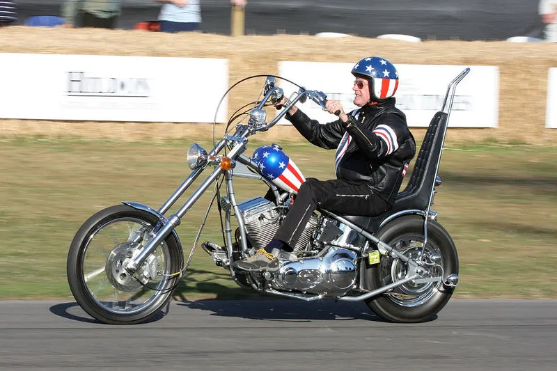
Image of a typical American Chopper
DESIGN METHODOLOGY/APPROACH:
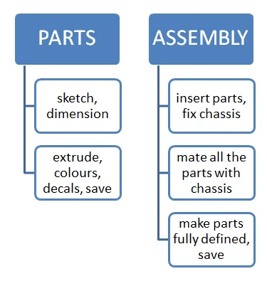
To design the American Chopper the below steps are to be followed.
For part modelling:
- In the Solidworks software open a part file and select the unit system to MMGS and select a plane.
- Sketch the required profile on that plane, add dimensions, make fully defined and extrude it as required in the feature tab.
- Apply colour and decals to the part in the Appearance tab.
- Then name the part file and save it.
For assembly modelling:
- Insert components one by one.
- Make the Chassis fixed and mate all the components with the chassis one by one.
- Make all the components fully defined and then save the file.
- Also this American Chopper is made with bottom-up assembly approach where first the parts are designed in individual part file(.SLDPRT) and then assembled in another assembly file(.SLDASM).
DESCRIPTION:
Features/tools used while designing:
- Line: Used to make a straight profile/surface using line tool or can be used to make reference axis.
- Circle: Used to make circular profile by using origin.
- Rectangle: Used to make rectangular profile which has length and breadth and also used to make rectangular profile using origin.
- 3-point Arc: Used to make arc profile/semi-circle using 3 different points, which later can joint two different profiles.
- Spline: This tool is used to make a spline which adds curves together to make it continuous or irregular curvy structure.
- Convert Entities: This tool is used to project edges of a face onto the active sketch.
- Offset Entities: Used to copy of the existing geometry and offset it to a required distance and directions.
- Extrude Boss: Used to make a 3D body by extruding the 2D sketch in the Feature tab.
- Revolved Boss: Used to make a cylindrical 3D body from a circular sketch which has circle as edge and centre axis.
- Swept Boss: Used to make a sweep by moving a 2D profile along a 2D/3D path.
- Extruded Cut: It is used to remove material by projecting a shaped sketch normal to the sketching plane.
- Fillet: It is used to make the internal/external edge of a 3D body a rounded face.
- Chamfer: Used to make the sharp edge of a body a flat face.
- Pattern: It is used to add material to the 3D body in a circular/linear direction.
- Shell: Used to remove extra material from the body except for the inner thickness of the body.
- Mirror: Used to mirror body along a reference/axis.
- Reference Geometry: Used to create plane with the help of reference plane/face/point/edge.
- Combine: Used to combine two solid bodies.
- Knit Surface: Used to join multiple surfaces into one surface in Surface tab.
Images of the part files:
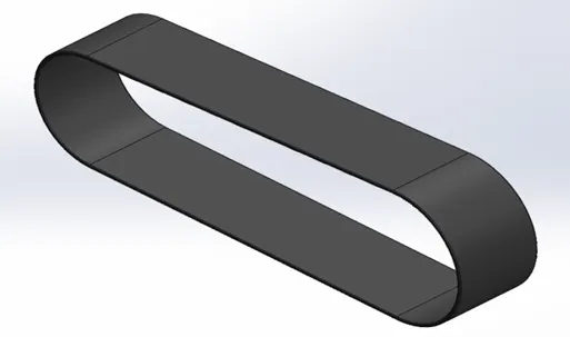 (Transmission belt)
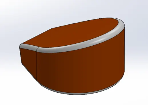 (Oil Tank)
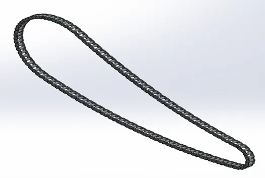 (Chain)
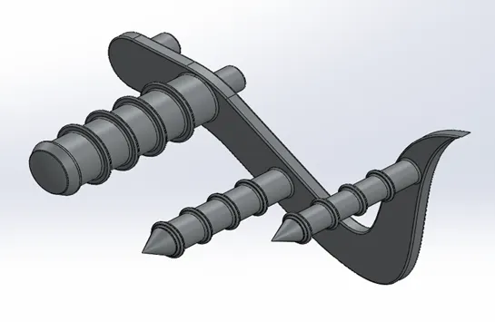 (Pedal)
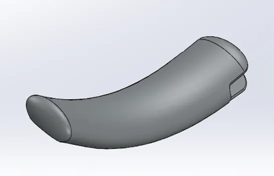 (Kickstand)
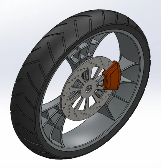 (Front wheel)
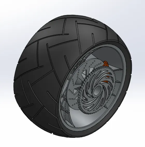 (Rear wheel)
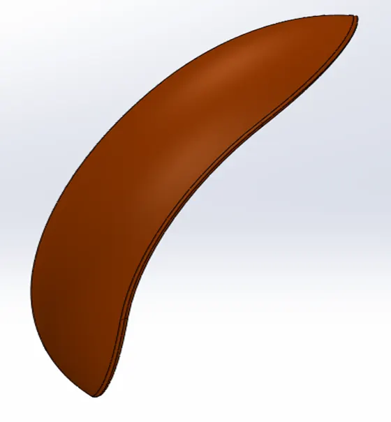 (Front Fender)
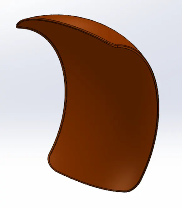 (Rear Fender)
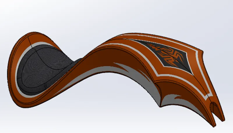 (Gas tank)
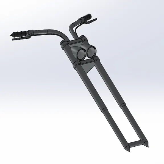 (Front fork)
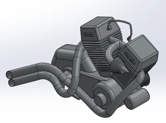 (Engine)
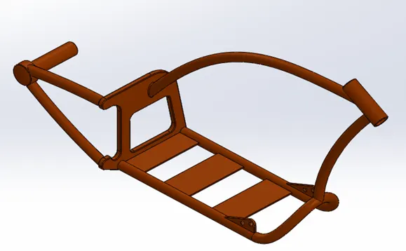 (Chassis)
ASSEMBLY MODEL VIEW ORIENTATION:
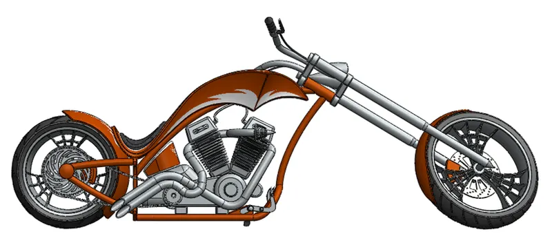
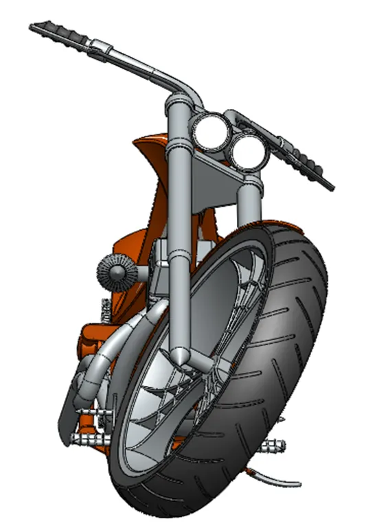
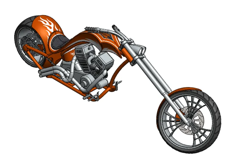
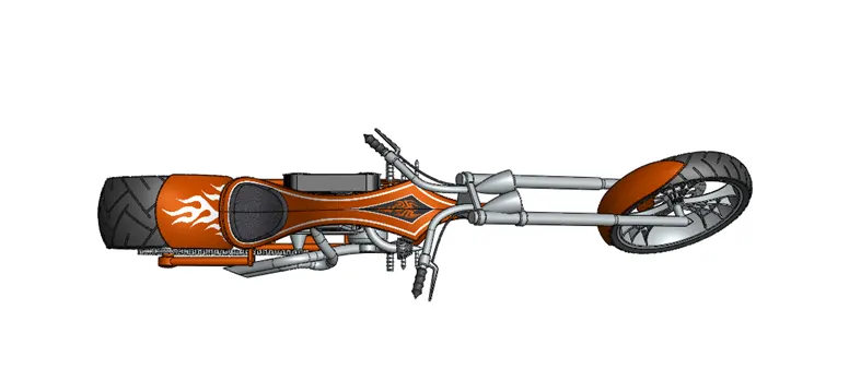
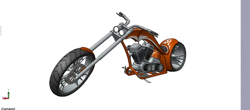
PHOTO REALISTIC RENDERING USING SOLIDWORKS VISUALIZE:
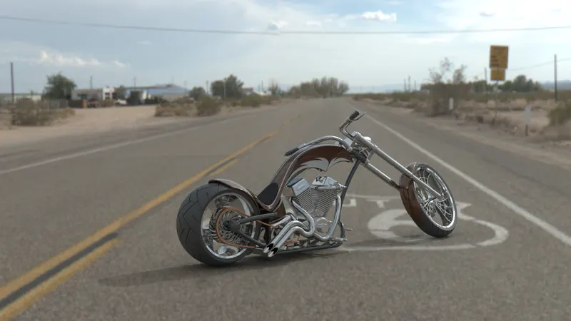
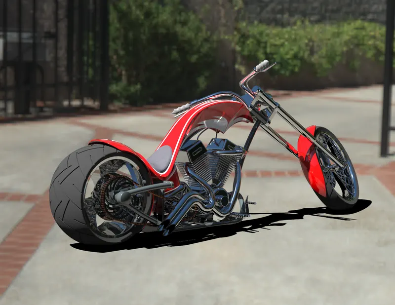
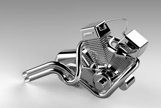
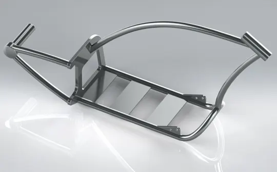
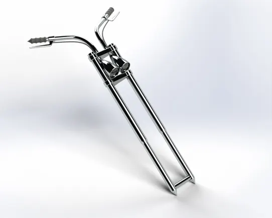
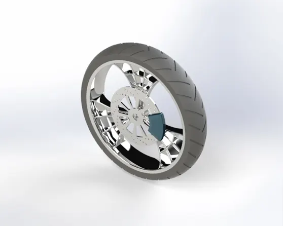
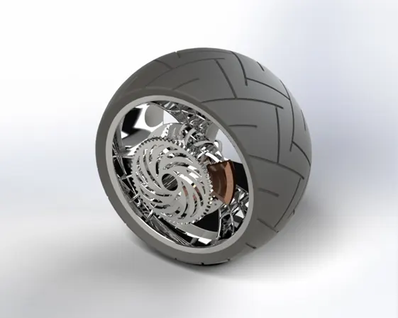
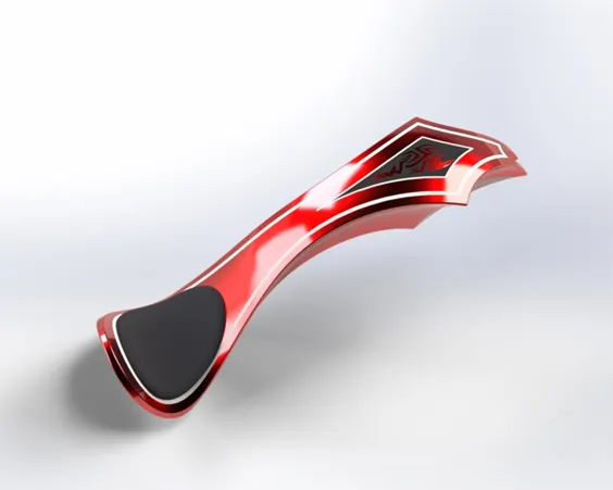
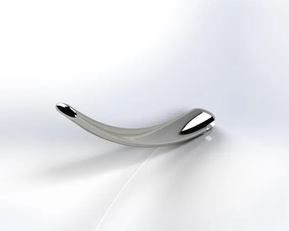
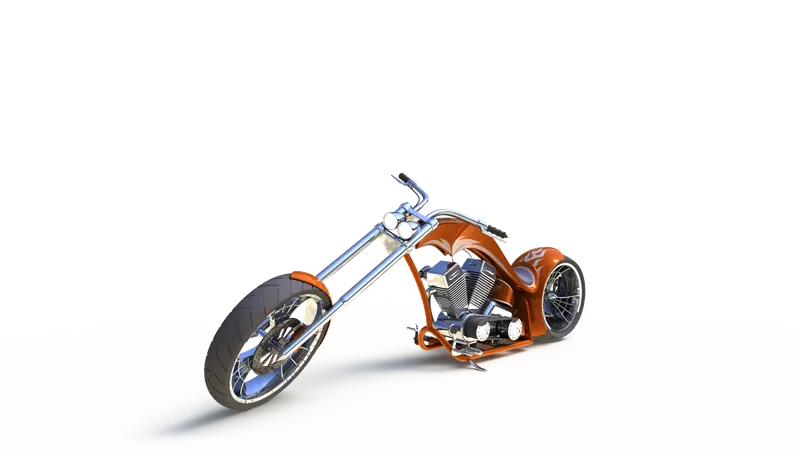
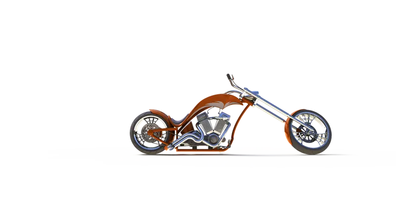
The photo-realistic rendering of the chopper is done using Solidworks Visualize 2020 software where both the assembly and parts are rendered. In this rendering some of the rendering features like Scenes, Lights, Camera, Appearance, and Decals etc. are used.
Rendering Images (assembly):
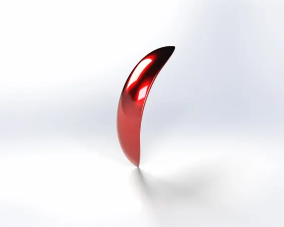
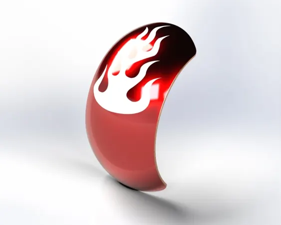
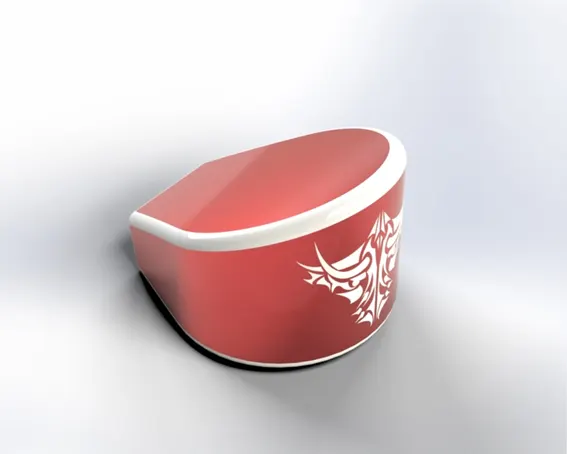
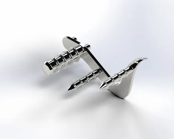
Rendering Images (Parts):
Rendering Images from Solidworks PhotoView 360:
CONCLUSION:
So this is how the American Chopper was modelled, assembled and rendered using Solidworks.