Photo Realistic Rendering
Title of the project- Assembly of the chopper and its photo realistic rendering.
Objective- to make the model look more realistic and presentable using different tools.
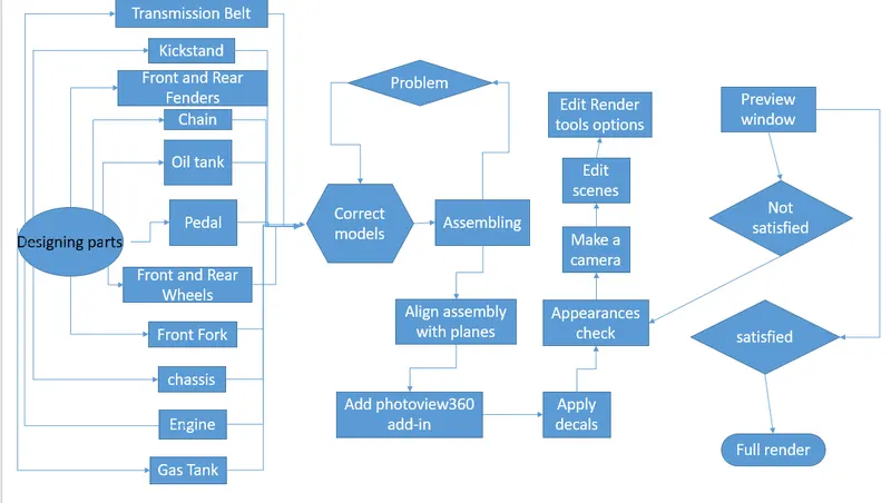
Introduction- in the past challenge, we completed assembly of an american chopper bike. In this project we level the model accurately and realistically. We make the model look more appealing and realistic with better presentation and model blending background. We are setting up the model in an environment that it looks realistic and not floating. We apply decals to make it better looking. We use different appearances and options available in photoview360 and solidworks Visualize to make the model look realistic.
Flowchart-
Model images-
1. Transmission belt:
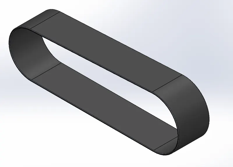
features used- boss extrude and fillets.
2. Kickstand
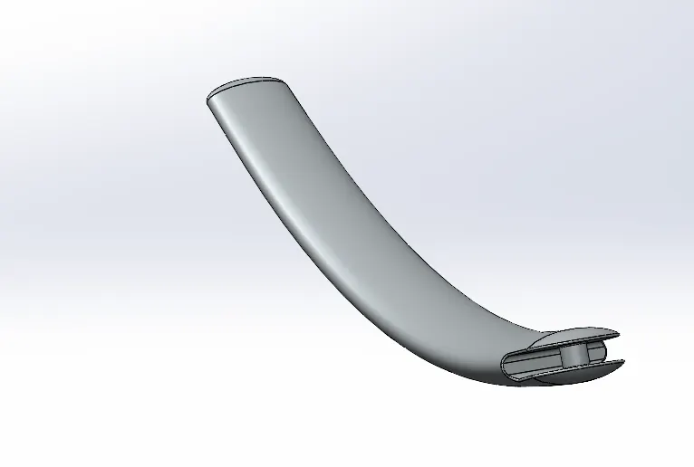
feature used- loft of the main geometry, extrude cut near an end of loft, extrude boss base between two faces of the cut geometry, dome at both ends of the loft ,and fillets.
3. Front fender
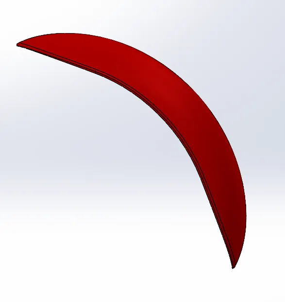
features used- revolve boss base used for basic tire shaped geometry but upto certain less angles on both direction1 & 2, split cut to remove material and get a triangular shaped geometry at both sides of the revolved geometry, and fillets.
4. Rear fender
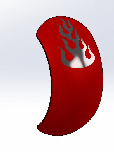
features used- made using similar feaures like front fender but shell feature is also used to remove material and make a shell of certain thickness. flaming decal is also used in label mode in this part.
5. Chain
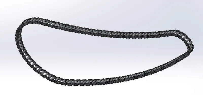
features used- boss extrude three times to create 2 different pins and a connecting link. fillets are also used in each pin and connecting link. pattern of chain links were made.
6. Oil tank
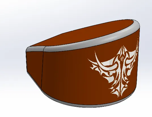
features used- two boss extrudes were done and the common gemetries were combined, shell feature was used to make the part hollow with certain thickness, and fillets. decals are also used in this part using photoview360 render tools.
7. Pedals
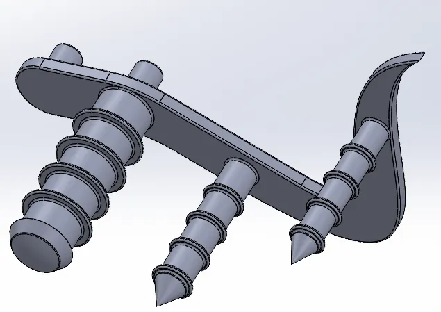
features used- boss extrudes, dome at the end of one first rod, linear pattern of rings, chamfers to create conical ending rods, and fillets.
8. Front wheel
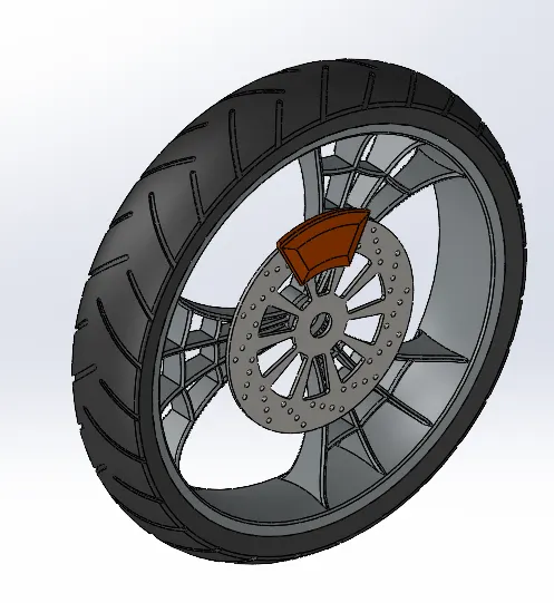
features used- revolved boss base to create tire. boss extrude, extrude cut, circular pattern to create rim. Boss extrude, extrude cut, and linear pattern for rotar. Boss extrude and chamfers for callipers. Fillets are used on all the parts.
9. Rear wheel
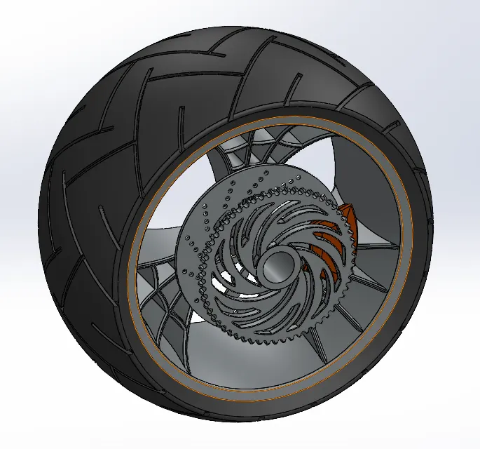
features used- features used are similar to those used in front wheel but sprocket is added in this and it is made up of features extrude boss base, extrude cut, chamfers ,circular patterns, and fillets.
10. Front fork
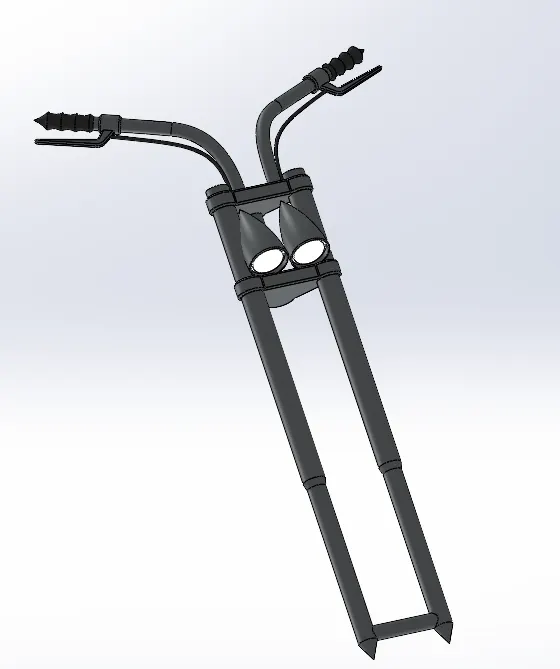
features used- extrude boss for the two forks. revolved boss base for head lights, sweep for handles, mirror for half of the part and fillets.
11. chassis
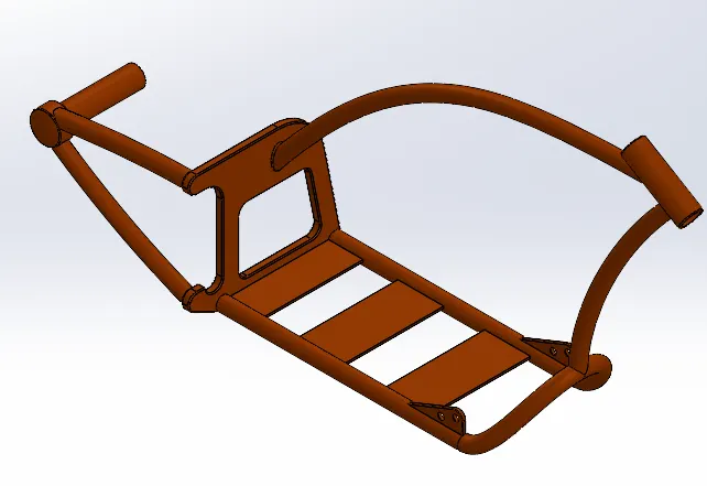
features used- sweep, boss extrude and cut extrude, and split are used to make the basic structure. Chamfers, fillets and a dome feature was also used.
12. Engine
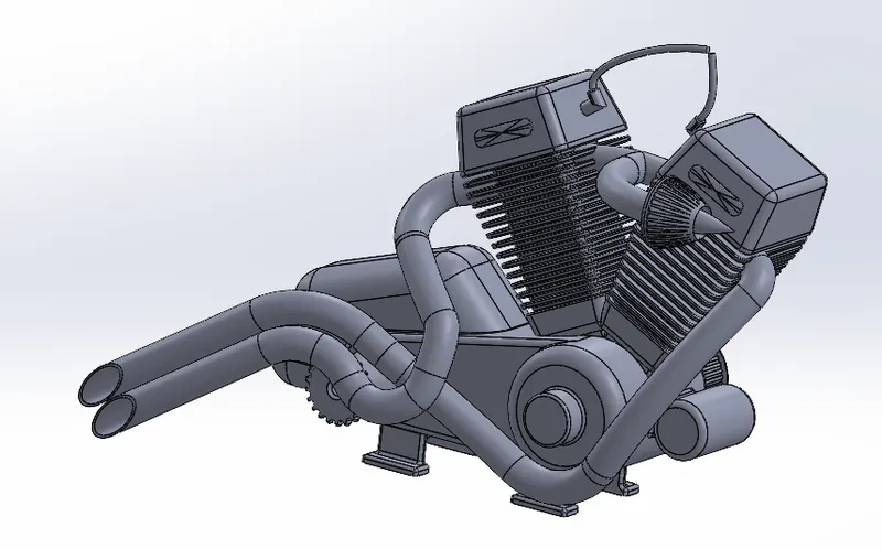
feature used- boss extrude, extrude cut, sweep, linear pattern, circular pattern, chamfers and fillets are used in this part. Variuos curve and two composite curve were also used for sweep.
13. Gas tank
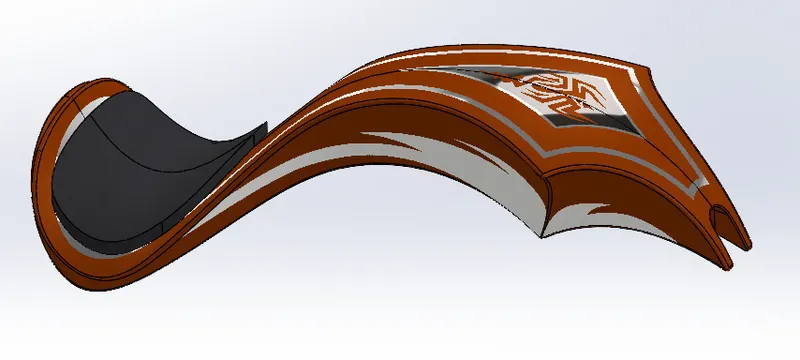
features used- surface sweep, surface loft, and boundary surfaces are used make the major geometry. Surface knit is used to join all the surfaces. Surface extrude is used to make the seat. cut sweep is used to make way for attaching to chassis. shell is used to make this a hollow structure of certain thickness. fillets are also used around the surface edges. decals are also used in this part using photoview360 render tools.
Assembly-
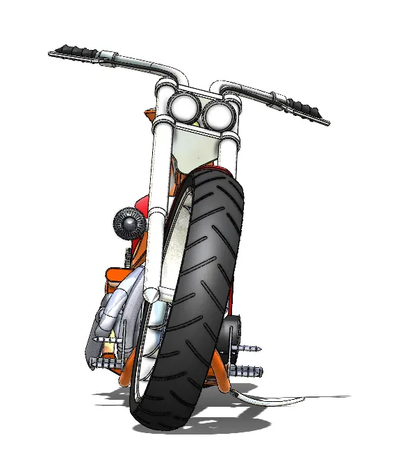
Front view:
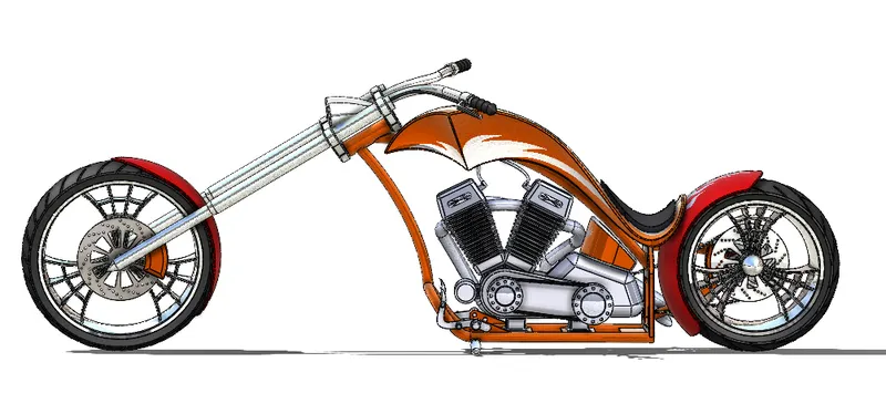
side view:
isometric view:
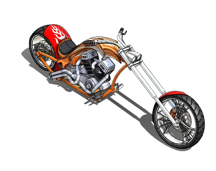
camera view:
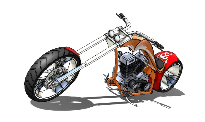
top view:
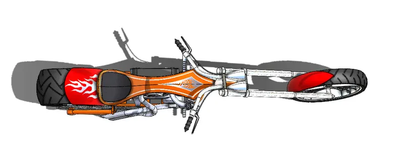
Rendered images-
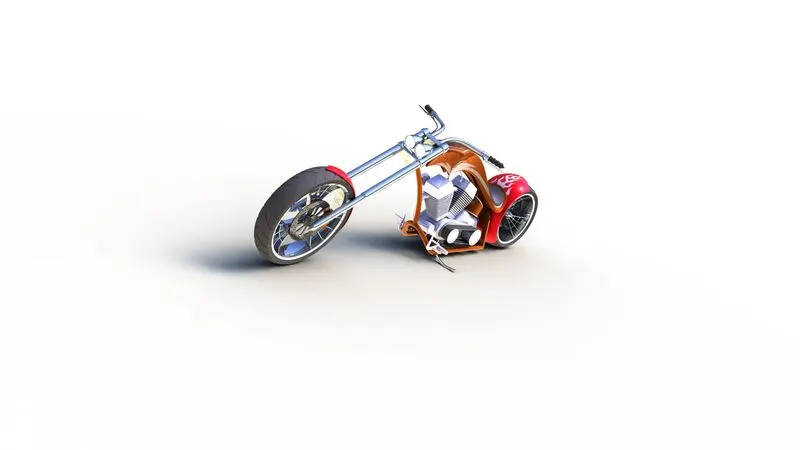
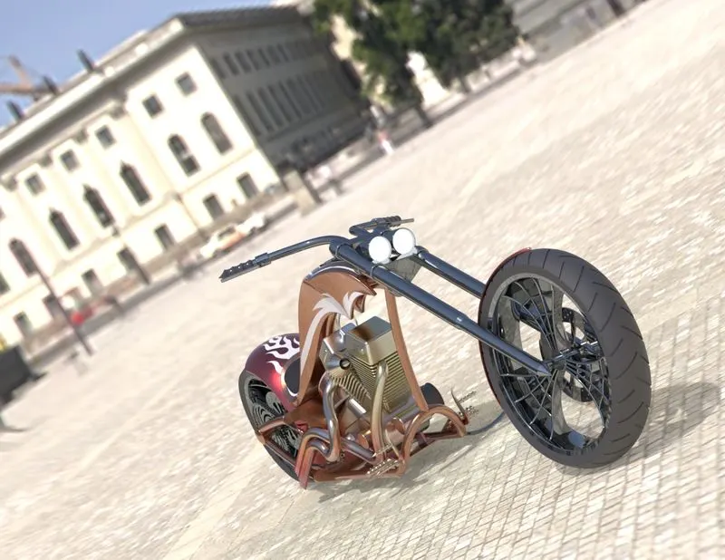
conclusion: The model was successfully assemblem, environment setup was done, image rendering using photoview360 and solidworks visualize was also performed. Realistic model was obtained.