Photo Realistic Rendering
MODELLING AND RENDERING OF AN AMERICAN CHOPPER
OBJECTIVE
The objective of this project is to create each part file required for the chopper and assemble them based on the requirements in the model, to create an American Chopper bike. We have to learn all the features required for designing each separate part for the chopper and have to learn the assembly techniques required for the chopper.
INTRODUCTION
The project is about the designing of an American Chopper. First, we have to understand what are the parts that are required for designing the chopper and to learn the functionalities of each part. We have to create each part separately and learned to give them appearances for each part based on their applications. Finally, to assemble and renders them realistically based on the functionality of that vehicle.
DESIGN METHODOLOGY
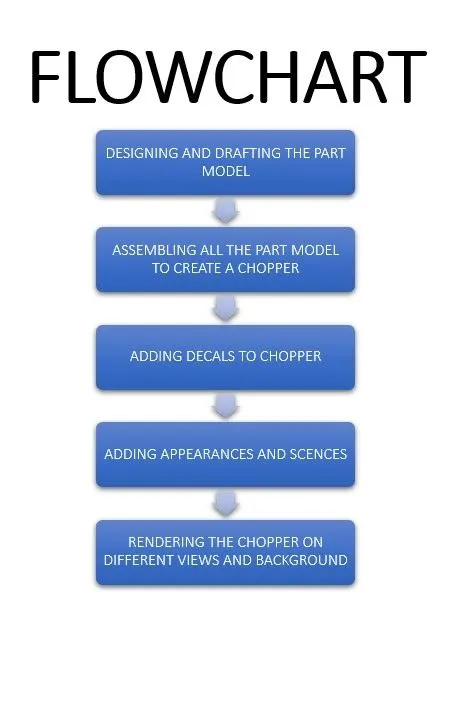
In this project we have created using the bottom-up approach. First, we designed each part separately based on their requirements and applied different appearances for each part file based on the usage and applications. After creating all the part files, we have to assemble all the individual parts to create a chopper by adding relations between the parts. After assembling, we have to check if the assembly is over defined. If the assembly is over defined, make them fully defined by adding or suppressing the relations. We have added decals to the gas tank, front fender, rear fender and oil tank to make them more attractive. After completing the assembly process and decals, we have to go for rendering the chopper for realistic and attractive outcome of the chopper. The design methodology of chopper is explained by flowchart mentioned below.
DESCRIPTION
In this we are going to see how all the part files of the chopper are designed and the features required to design a part. The individual parts required to create a chopper are listed below.
- TRANSMISSION BELT
- CHAIN
- KICKSTAND
- OIL TANK
- REAR FENDER
- FRONT FENDER
- FRONT WHEEL
- REAR WHEEL
- FRONT FORK
- OIL TANK
- ENGINE
- CHASSIS
- GAS TANK
- PEDAL
TRANSMISSION BELT
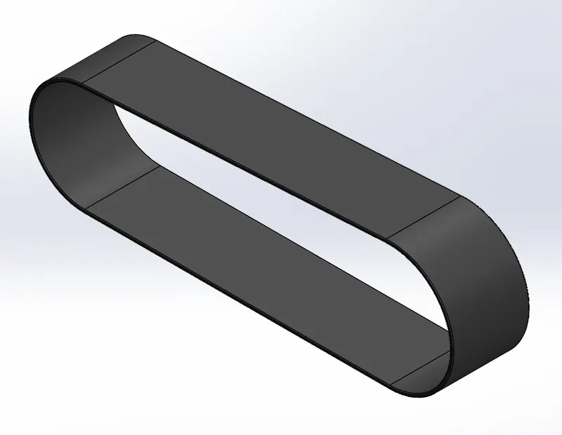
It is used to transmit rotational energy from one shaft to another which has a parallel or non-parallel axis of rotation. The rubber material is used for transmission belt. Mostly, pulleys and belts are used to transmit motion efficiently. Sometimes, the belt attached to the pulley are twisted to provide a reverse motion.
Commands used: The features that are used to create a belt are listed below.
- 2-D sketch
- Dimensions
- Appearances
- Fillet
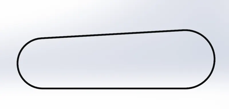
- Offset entities
- Extrude boss
OFFSET ENTITIES
This feature is used to create a copy of your existing geometry and copies it an offset. Offset entities are a great tool for enlarging and shrinking your geometry.
EXTRUDE BOSS
It is used to project a selected 2-D sketch into a3D model or solid geometry. It is used to extend a sketched profile in one or two directions as either thin feature or a solid feature.
FILLET
Fillet creates a rounded internal or external face on the part. We can add fillet to all the edges of a face, selected sets of faces, selected edges, or edge loops.
CHAIN
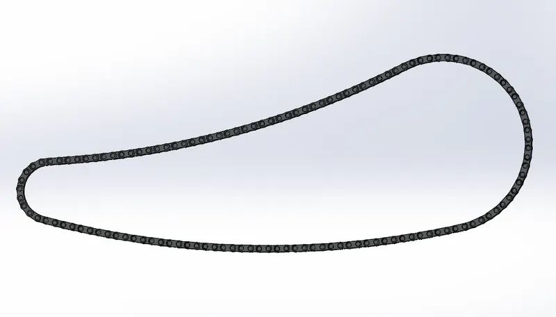
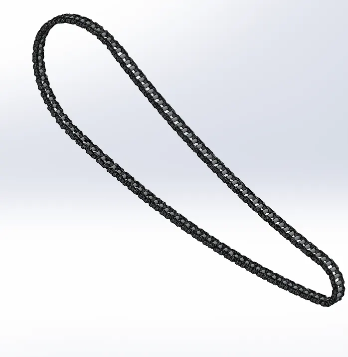
Chain in the chopper is used to transmit the engine power from the end of the transmission line to the sprocket of the rear wheel. A well lubricated chain has a maximum efficiency in transmission when compared to all other transmission systems.
Commands used: The features that are used to create a chain are listed below.
- 2-D sketch
- Dimensions
- Appearances
- Fillet
- Curve driven pattern
- Mirror entities
- Extrude boss
CURVE DRIVEN PATTERN
Curve driven pattern is used to create a pattern of a solid body or sketch along a planar or 3D curve. The curve used can be open or a closed curve.
MIRROR
Mirror feature allows us to mirror any solid body or sketch with respect to any selected plane. It is very useful in creating a symmetric body or sketch.
KICKSTAND
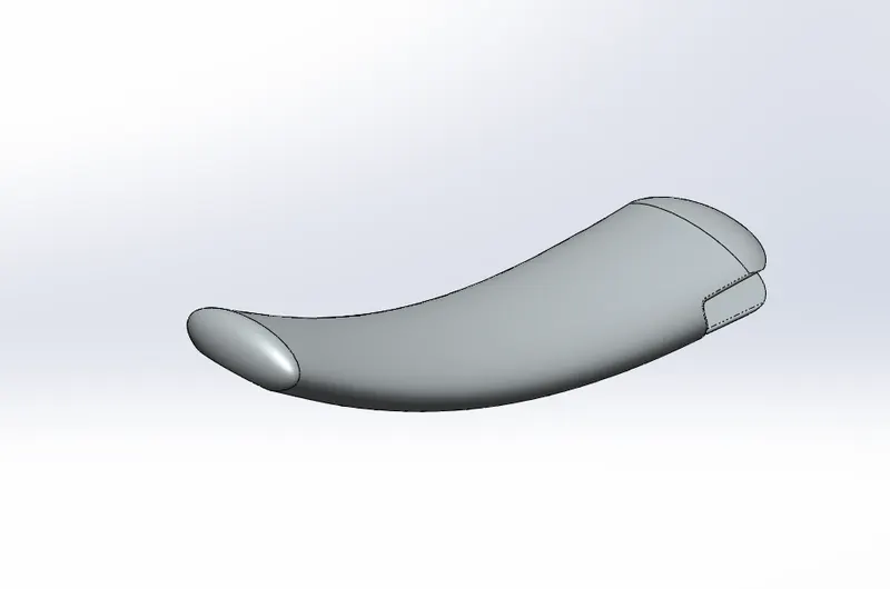
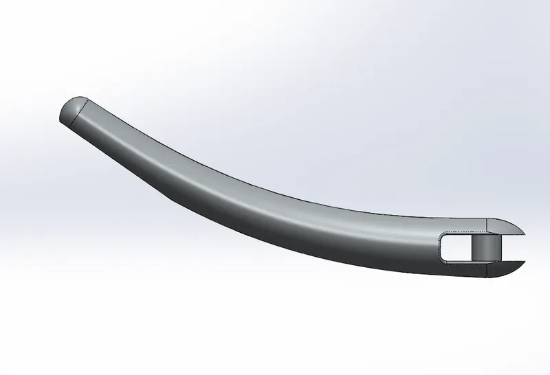
Kickstand supports the whole chopper while it is in rest condition. It will be made of steel to withstand the whole weight of the chopper and to avoid rusting it will be chrome plated.
Commands used: The features that are used to create a Kickstand are listed below.
- Dome
- Split
- Extrude cut
- Lofted boss
DOME
This feature creates a dome tangent to the adjacent face. It uses the radius of arc for the basis of dome.
SPLIT
The split tool projects an entity (i.e., Sketch, solids, surface, face, plane or surfaces spline) to surfaces or curved or planar faces. It divides the selected face into a multiple face. We can split curves on multiple bodies. We can also use the split feature to separate and delete the parts that we don’t need.
EXTRUDE CUT
This feature uses the 2-Dsketch to remove material from the selected part or body.
LOFT BOSS
This feature creates a 3-D shape by making transitions between multiple profiles and guide curves. It will be very useful in creating complex surfaces.
OIL TANK
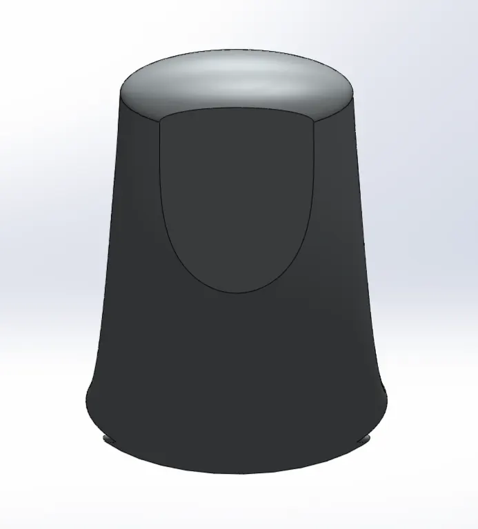
Oil tank is used as an oil reservoir where the oil is stored for the lubrication of the engine.
Commands used: The features that are used to create an oil tank are listed below.
- Shell
- Fillet
- Combine
- Extrude boss
- Decals
SHELL
It is used to define the thickness of a thin and thick shell elements.
COMBINE
It is used to convert two or more separate solid bodies into one solid body.
FRONT FENDER
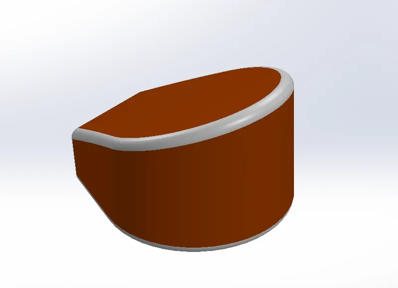
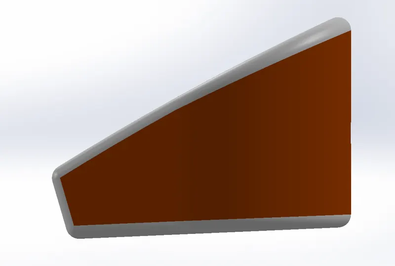
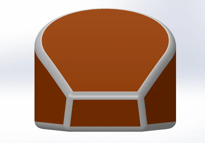
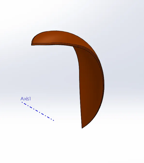
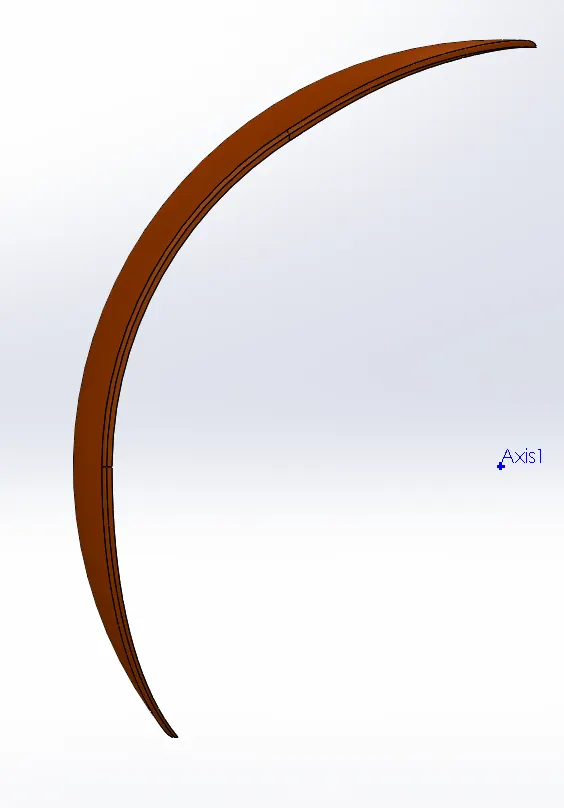
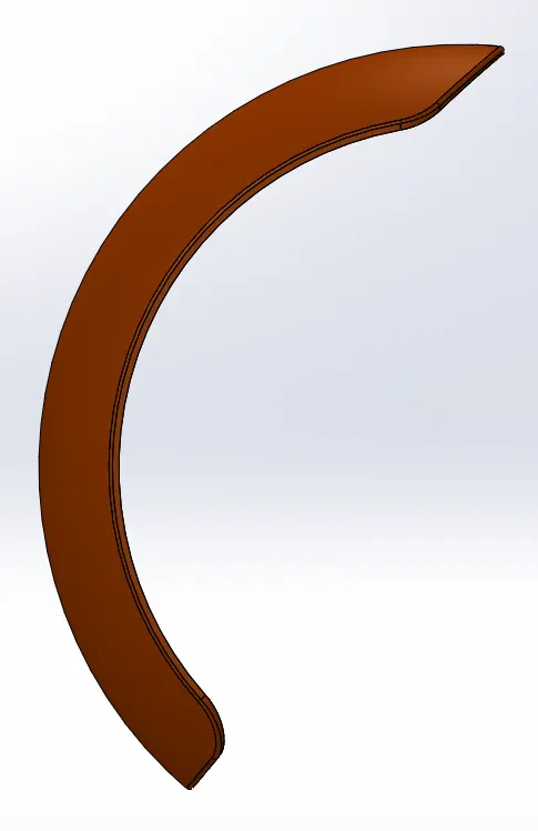
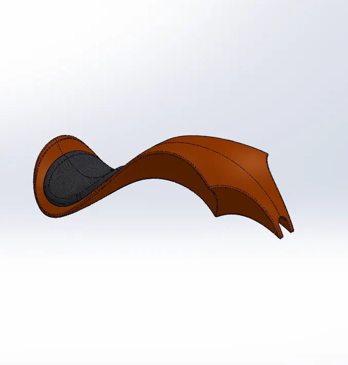
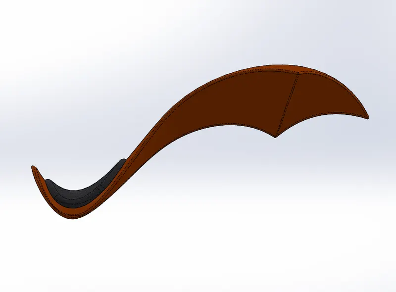
Front fender comes for the front wheel of the chopper which acts as a guard to the wheel and protects the chopper from the mud and dirt splashing all over the body.
Commands used: The features that are used to create a Front fender are listed below.
- Revolve
- Extrude boss
- Split
Shell 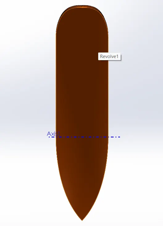
REAR FENDER
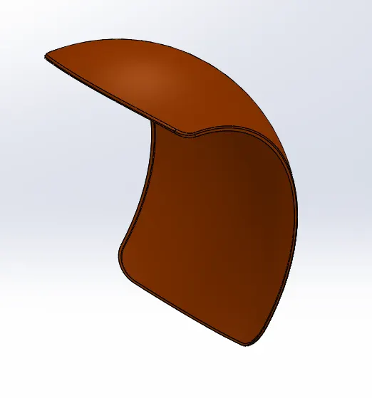
Rear fender comes for the rear wheel and has the same functions as the front fender.
Commands used: The features that are used to create a rear fender are listed below.
- Revolve
- Split
- Shell
- Decals and appearances
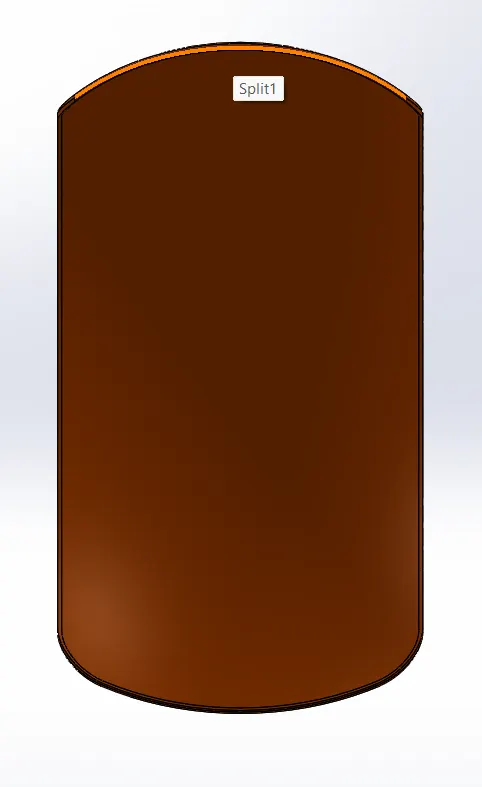
DECALS
A decal is an 2D image which can be applied on the part for aesthetics or instruction labels to the parts.
PEDAL
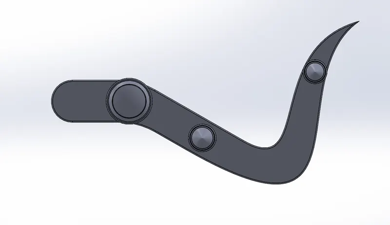
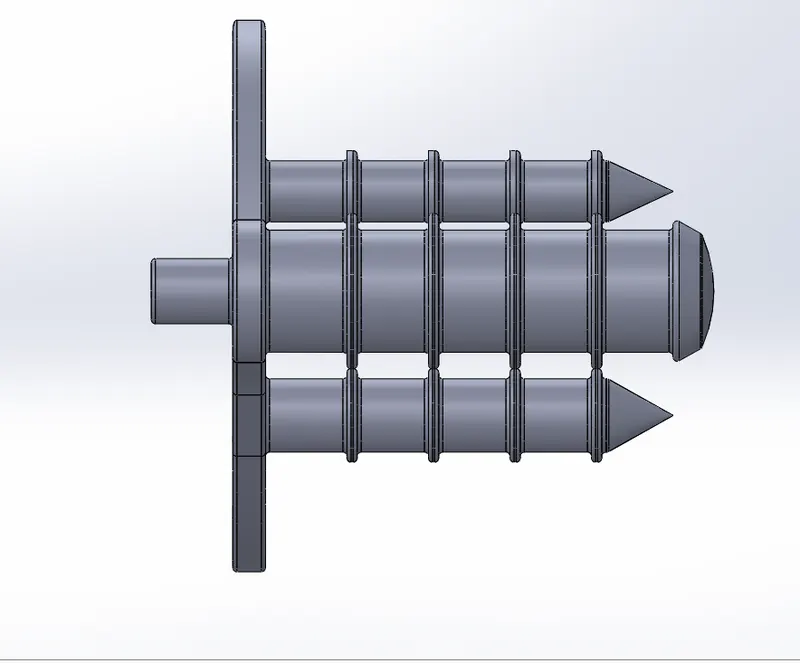
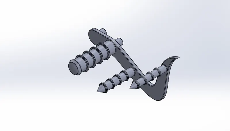
Pedal is the foot lever which is used to activate the rear brake of the chopper and the other pedal will have the gear lever attached to them.
Commands used: The features that are used to create a pedal are listed below
- Extrude boss
- Revolve
- Linear pattern
- Dome
LINEAR PATTERN
It is used to create multiple instances of one or more features that we can space uniformly along one or two linear paths.
WHEEL
It is the circular body that supports the total weight of the chopper while chopper is in the motion and it enables the necessary chopper to move smoothly over the surface.
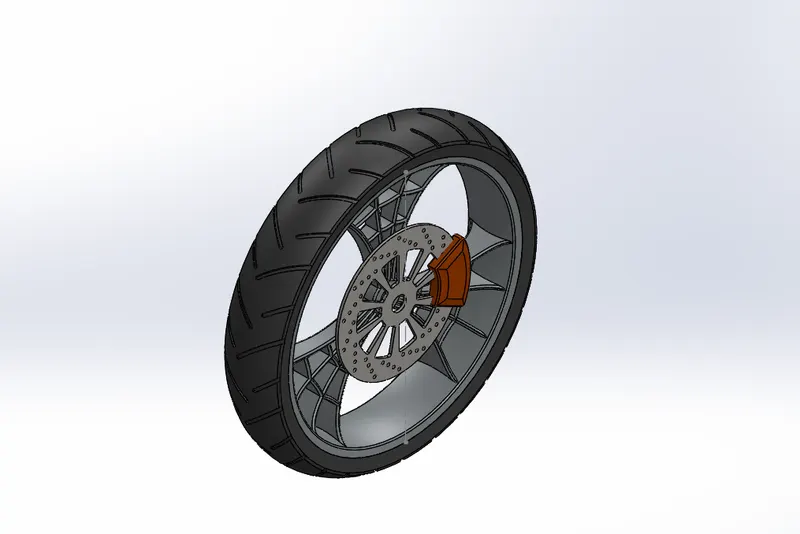
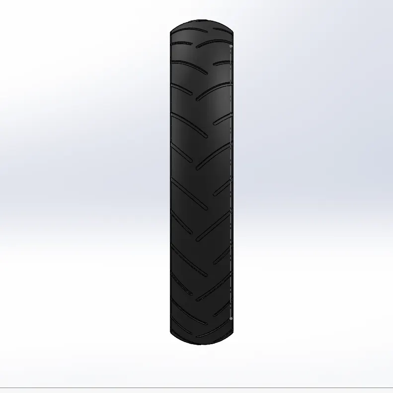
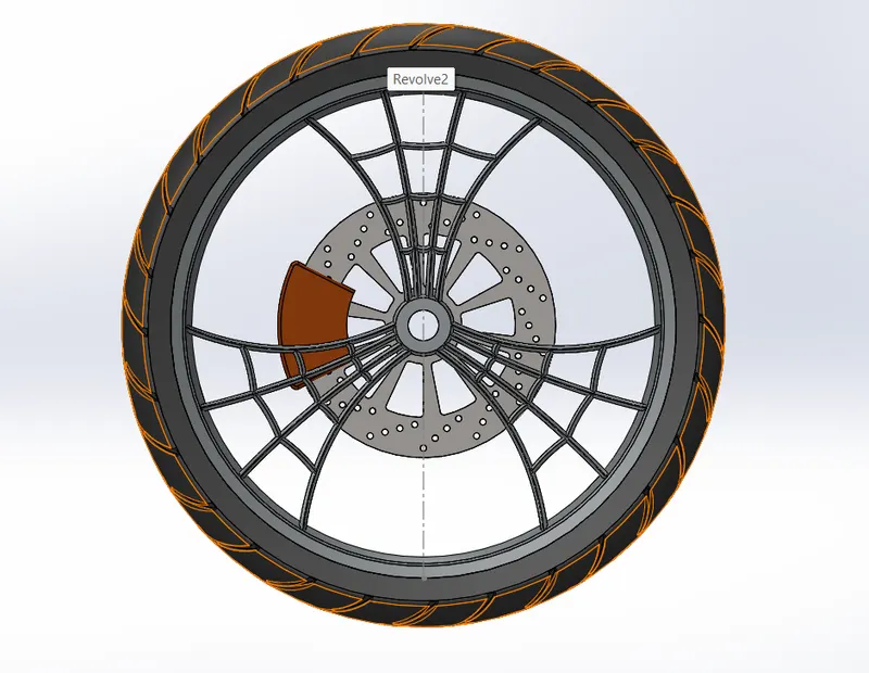
FRONT WHEEL
Front wheel is attached to the front fork of chopper which changes the direction of the chopper.
Commands used: The features that are used to create a front wheel are listed below
- Revolve
- Extrude boss
- Offset entities
- Trim entities
- Chamfer
- Mirror
- Revolve cut
- Linear pattern
- Combine
- Extrude cut
- Circular pattern
- Fillet
Circular pattern
It is used to create multiple instances of one or more features that we can space uniformly around a selected axis.
CHAMFER
Chamfer creates a beveled surface over the selected area or edges of the parts.
TRIM
Trim entities are used to trim the sketches that are not required for the modeling.
REVOLVE CUT
It allows us to cut a profile along the axis creating complex geometry in a single feature.
REAR WHEEL
Rear wheel is attached to the back end of the chassis of the chopper. It drives the chopper by receiving power from the engine to the sprocket attached to the wheel through the chain.
Commands used: The features that are used to create a rear wheel are listed below
- Revolve
- Extrude boss
- Offset entities
- Trim entities
- Chamfer
- Mirror
- Revolve cut
- Linear pattern
- Combine
- Extrude cut
- Circular pattern
Fillet
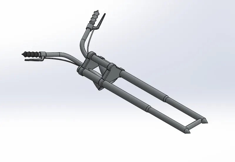
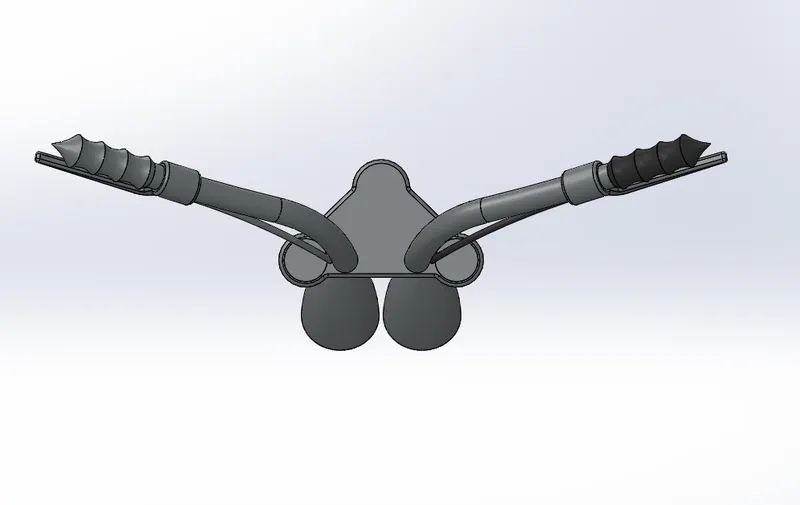
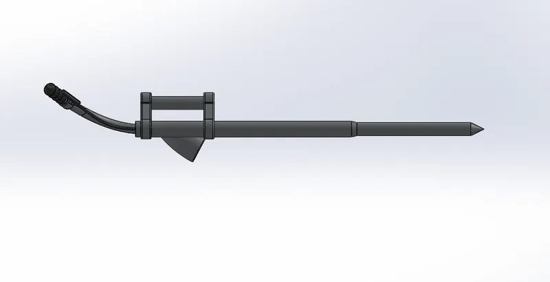
FRONT FORK
Front fork provides the direction to the front wheel, which changes the direction of the chopper. It carries the head light and acts as shock absorber too. It handles all the imperfections in the road and separates rest of the body from the impact.
Commands used: The features that are used to create a front fork are listed below
- Dome
- Circular pattern
- Linear pattern
- Mirror entities
- Trim entities
- Projected curve
- Revolve boss
- Extrude boss
- Swept boss
- Extrude cut
- Revolve cut
- Combine
SWEPT BOSS
It is used to sweeps a closed profile through an open or closed path.
PROJECTED CURVE
It is used to create a 3-d curve by creating two or more 2-D curve and project them into a single 3-D curve.
GAS TANK
It is the place where the fuel gets stored. From this tank the fuel passes through the fuel filter and fuel pump gets into the engine cylinder for ignition.
Commands used: The features that are used to create a Gas Tank are listed below
- Trim
- Shell
- Mirror
- Boundary surface
- Split line
- Knit surface
- Swept cut
- Lofted surface
- Swept surface
- Extrude surface
- Surface trim
- Projected curve
SWEPT CUT
It is used to remove the material from the three-dimensional surface through the guide curves and vertex points.
SWEPT SURFACE
In order to create a sweep surface, we have to create a sweep profile, sweep path and guide curve.
SURFACE TRIM
It is used to trim the surfaces in solid works.
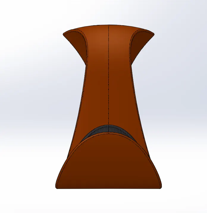
CHASSIS
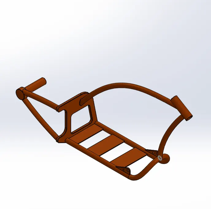
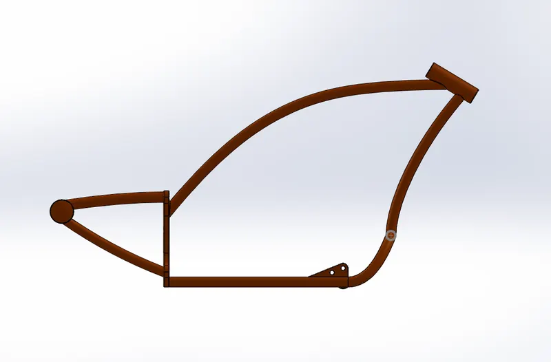
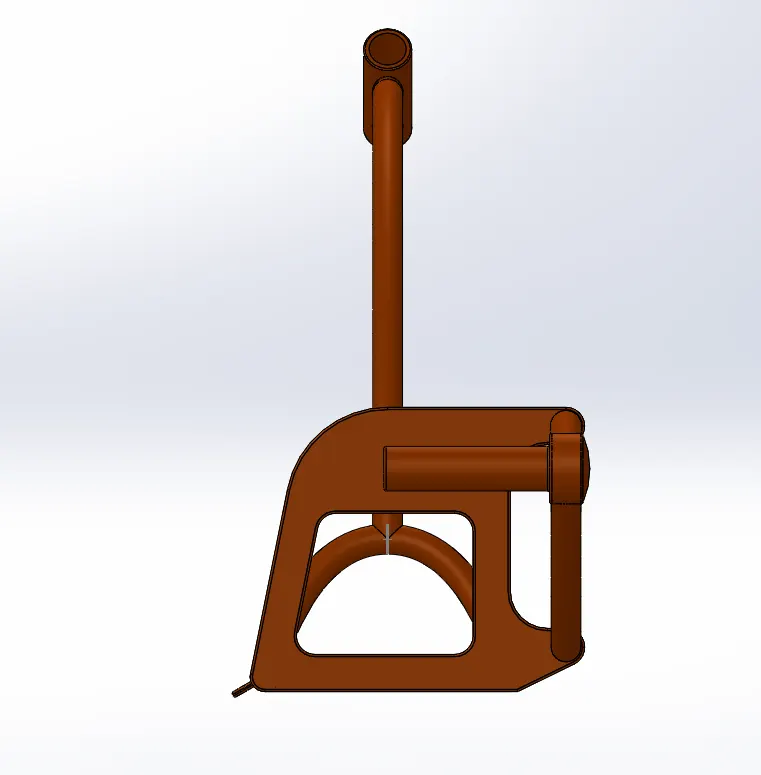
Chassis is a skeleton of the vehicle. The body of the vehicle is rested on the chassis. The chassis connects the body of the chopper to the wheels of the chopper.
Commands used: The features that are used to create a Chassis are listed below.
- Trim
- Offset
- Extrude boss
- Extrude cut
- Projected curve
- Chopper blueprint (used as a reference)
- Sweep boss
- Dome
- Split
- Combine
- Revolve boss
- Fillet
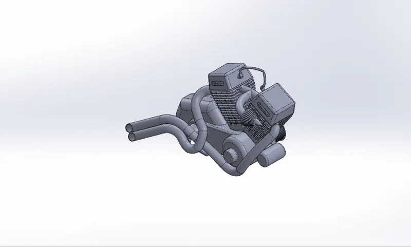
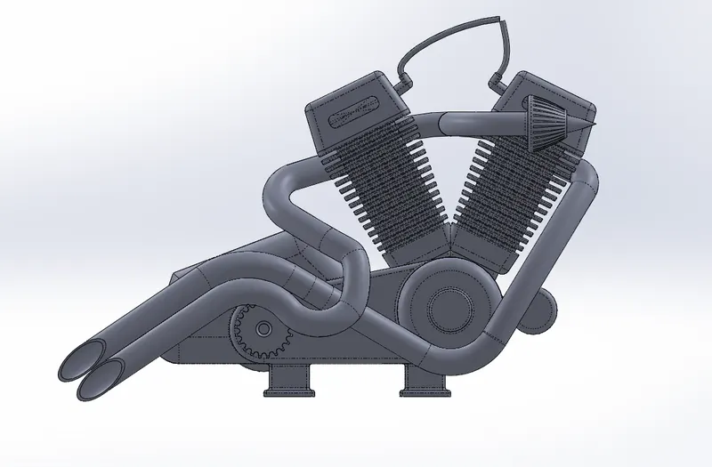
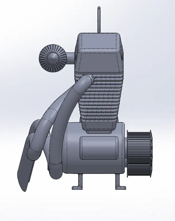
ENGINE
Engine is called the heart of the chopper because it provides the necessary power to move the vehicle. Engine converts chemical energy of fuel into mechanical energy and transmits the energy through transmission systems.
Commands used: The features that are used to create an Engine are listed below.
- Extrude boss
- Fillet
- Extrude cut
- Circular pattern
- Reference plane
- Revolve boss
- Sweep boss
- Dome
- Chamfer
- Linear pattern
- Mirror
- Split
- Combine
- Projected curve
- Composite curve
COMPOSITE CURVE
This feature is used to combine two or more 3D or 2D curves into a single resultant curve in 3D.
ASSEMBLY OF CHOPPER
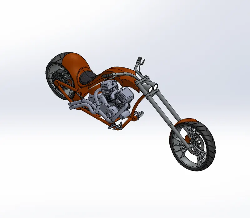
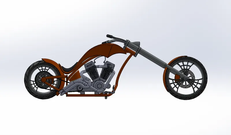
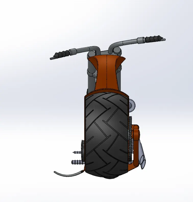
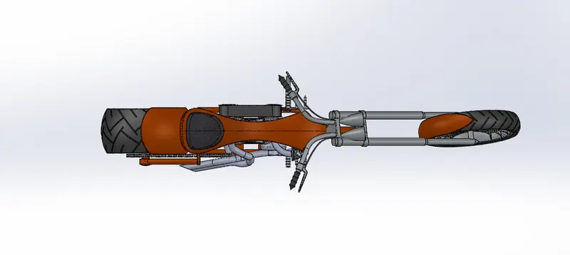
After creating all the part files, all the part files are taken to the assembly section and the assembly of chopper is made through the mate features such as parallel, coincidence tangent etc.,
Commands used: The features that are used to assemble the chopper are listed below.
- Mates
MATES
Mates feature is used to create a relation between the two parts or two faces or two edges by using the coincidence or tangent or parallel etc., which is used to assemble the parts required for the chopper.
RENDERING
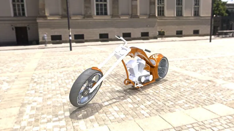
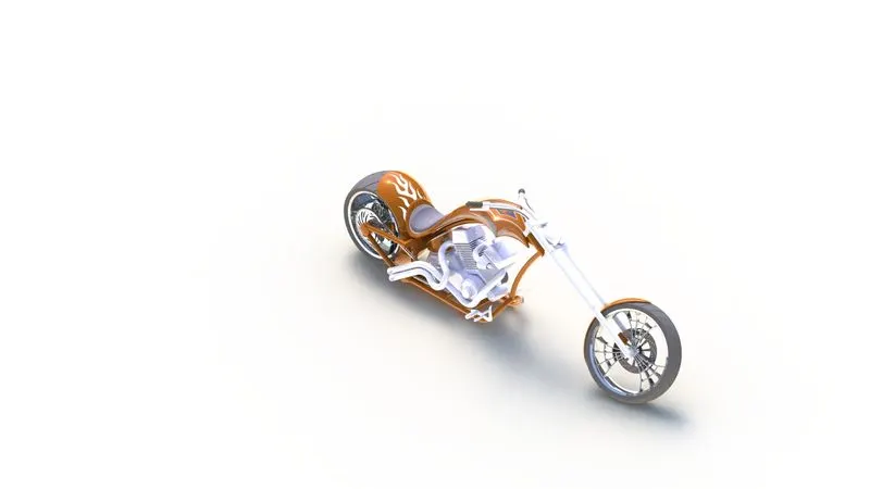
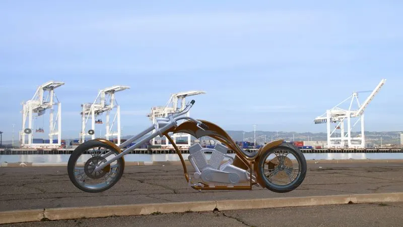
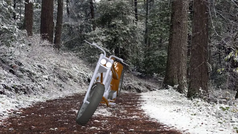
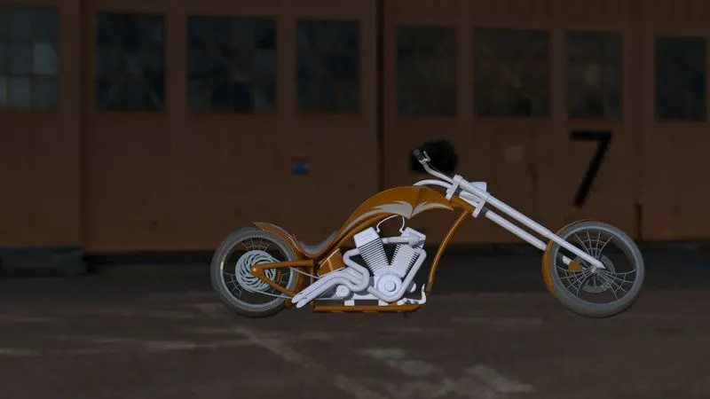
Rendering is the process of creating a 3D or 2D model into a photorealistic image by adding scenes and editing appearances and adding decals to the model.
CONCLUSION
- The individual components of the chopper are modeled and designed using the features.
- The separate part files are assembled into a chopper and rendering is done for the model.