Photo Realistic Rendering
Project Report Modelling & Rendering of American Chopper in Solidworks.
OBJECTIVE:-
In this project, we study about the how to design a bike aesthetics in Solidworks. For reference, I take American
chopper bike for designing. American Chopper is two wheeler. Solidworks is 3-D software by Dassault System.
Solidworks is used for designing new component, modify component, analysis, managing layout, drawing, etc.
Keywords: Engine, Frame, Gas Tank, Solid works, Two Wheeler, Wheel.
INTRODUCTION:-
SolidWorks is a solid modeling computer-aided design (CAD) and computer-aided engineering (CAE) application published by Dassault System. SolidWorks is a solid modeler, and utilizes a parametric feature-based approach which was initially developed by PTC (Creo/Pro-Engineer) to create models and assemblies. The software is written on Parasolid-kernel.
Parameters refer to constraints whose values determine the shape or geometry of the model or assembly. Parameters can be either numeric parameters, such as line lengths or circle diameters, or geometric parameters, such as tangent, parallel, concentric, horizontal or vertical, etc.
Building a model in SolidWorks usually starts with a 2D sketch (although 3D sketches are available for power users). The sketch consists of geometry such as points, lines, arcs, conics (except the hyperbola), and splines. Dimensions are added to the sketch to define the size and location of the geometry.
In an assembly, the analog to sketch relations are mates. Just as sketch relations define conditions such as tangency, parallelism,and concentricity with respect to sketch geometry, assembly mates define equivalent relations with respect to the individual parts or components, allowing the easy construction of assemblies.
Finally, drawings can be created either from parts or assemblies. Views are automatically generated from the solid model, and notes, dimensions and tolerances can then be easily added to the drawing as needed.
COMPONENTS OF AMERICAN CHOPPER
| Item No. | Part Name | Part Use |
| 1. | Transmission Belt | Transmit Power |
| 2. | Kickstand | Stand to Surface |
| 3. | Front Fender | Avoid From Mud |
| 4. | Rear Fender | Avoid From Mud |
| 5. | Chain | Transmit Power |
| 6. | Oil Tank | Store Lubricant |
| 7. | Pedal | Rest For Leg |
| 8. | Front Wheel | Guide Wheel |
| 9. | Rear Wheel | Power Wheel |
| 10. | Front Fork | Control Direction |
| 11. | Chassis | Mount All Components |
| 12. | Engine | Powerhouse of Vehicle |
| 13. | Gastank | Store Fuel |
| 14. | American Chopper | Transportation |
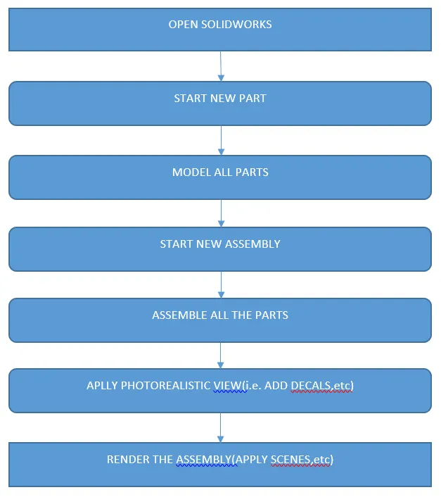
FLOW CHART FOR THE DESIGN METHODOLOGY
DESIGN OF COMPONENTS
TRANSMISSION BELT
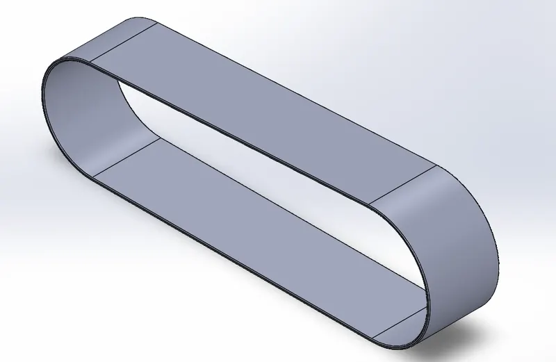
A belt is a loop of flexible material used to link two or more rotating shafts mechanically, most often parallel. Belts may be used as a source of motion, to transmit power efficiently or to track relative movement. Belts are looped over pulleys and may have a twist between the pulleys, and the shafts need not be parallel. To model tranmission belt various tools are used such as
- Sketch Tools:- 3 point arc, Line, Sketch Offset
- Feature:- Extrude, Fillet, Appearance
EXTRUDE:- This tool is used to drag your shape out to the left to create a 3D object. You can adjust your shape with the tool itself, or adjust its settings individually in the Property Bar.
FILLET:- The Fillet tool adds a highly specific fillet (arc) between two objects in the drawing, making each of the fillet's end points tangent to one of the objects.
APPEARANCE:- An appearance defines the visual properties of a model, including color and texture. Appearances do not affect physical properties, which are defined by materials. Every material is assigned a default appearance that emulates the look of the material.
KICKSTAND
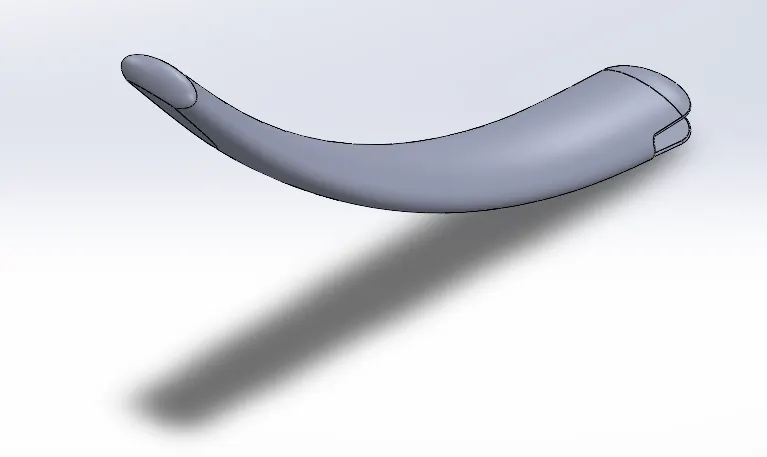
A kickstand is a device on a bicycle or motorcycle that allows the bike to be kept upright without leaning against another object or the aid of a person. A kickstand is usually a piece of metal that flips down from the frame and makes contact with the ground. It is generally located in the middle of the bike or towards the rear.
TOOLS USED
- Sketch Tools:- ellipse, spline, pierce
- Feature:- loft, split, dome, extruded boss, extruded cut, fillet, appearance
SPLINE:- The SOLIDWORKS software supports two types of splines, B-splines and style splines. You can use B-splines to create complex curves. You can define and modify them using several controls, including spline points, spline handles, and control polygons.
PIERCE:- A pierce relationship is required to ensure that two entities from different axis collide or cross paths – the center point of entities can be selected to move the sketch entity to a mutual position. To apply a pierce relation a line and a sketch point are required.
LOFT:- The loft feature is an important tool for (surface) modeling in SolidWorks. The loft feature creates a shape by making transitions between multiple profiles and guide curves. This tool is very valuable for modeling complex surfaces. You can do some really cool stuff when you use this feature properly.
SPLIT:- Tool projects an entity (sketch, solid, surface, face, plane, or surface spline) to surfaces, or curved or planar faces. It divides a selected face into multiple separate faces. You can split curves on multiple bodies with one command.
DOME:- The software calculates the distance using the radius of the arc as a basis for the dome. It creates a dome that is tangent to the adjacent cylindrical or conical face.
EXTRUDED BOSS:- Extrude tool is used to extend a sketched profile in one or two directions as either a thin feature or a solid feature.
EXTRUDE CUT:- You can use the Extrude tool to remove material by projecting a sketched section normal to the sketching plane. You can use open or closed sections to create a cut. Removing material using a closed section creates a slot. To create a cut, use the same depth options as for extruded protrusions.
FRONT FENDER
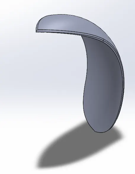
Fenders (or “mudguards”) are what will keep you from having a skunk stripe on your backside if you ride in the rain, and a front fender will help protect your feet and ankles from spray if you're riding in the rain or even through a puddle.
TOOLS USED
- Sketch Tools:- 3 point arc, sketch offset, line, spline
- Feature:- revolve, split, dynamic mirror entity, fillet, appearance
REVOLVE:- Revolve is a method of defining three-dimensional geometry by revolving a sketched section around a centerline. Use the Revolve tool to create a solid or surface feature, and to add or remove material.
DYNAMIC MIRROR ENTITY:- SOLIDWORKS Mirror Entities and Dynamic Mirror Entities are two excellent tools for mirroring 2D sketches. Mirror Entities allows a user to mirror their sketches about a common centerline after the sketch has been created. With Dynamic Mirror Entities, geometry can be sketched and mirrored simultaneously.
REAR FENDER
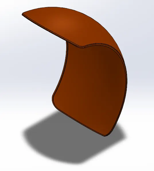
Fenders (or “mudguards”) are what will keep you from having a skunk stripe on your backside if you ride in the rain, and a front fender will help protect your feet and ankles from spray if you're riding in the rain or even through a puddle.
TOOLS USED
- Sketch Tools:- 3 point arc, sketch offset, line, spline
- Feature:- revolve, split, shell, dynamic mirror entity, fillet, appearance
SHELL:- The shell tool hollows out a part, leaves open the faces you select, and creates thin-walled features on the remaining faces. If you do not select any face on the model, you can shell a solid part, creating a closed, hollow model. You can also shell a model using multiple thicknesses.
CHAIN
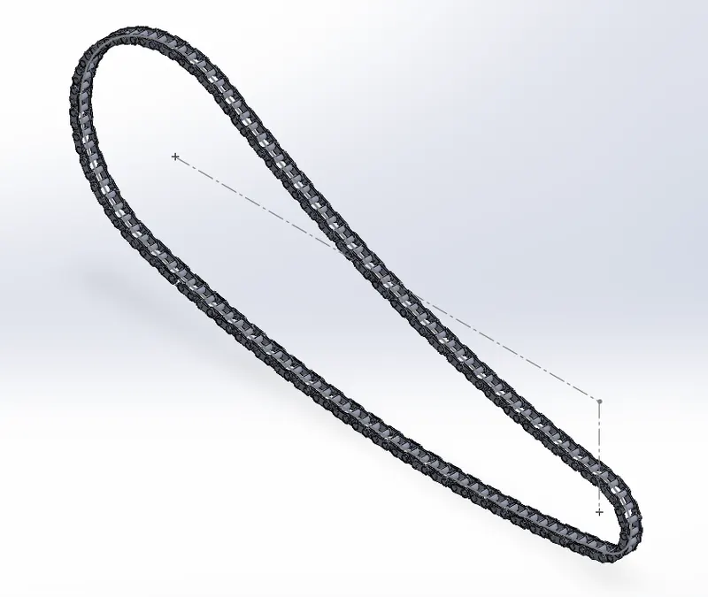
The drive chain mechanism needs two sprockets and a drive chain to function. A smaller sprocket is connected to the gearbox and a larger one is present on the rear wheel. The gearbox turns the front sprocket which, with the help of the chain drive, turns the rear wheel, putting the motorcycle in motion.
TOOLS USED
- Sketch Tools:- 3 point arc, centrepoint slots, circle
- Feature:- extrude boss, block, fillet, curve drive pattern, mirror, appearance
BLOCKS:- You can make, save, edit, and insert blocks for drawing items and sketch entities that you use often, such as standard notes, title blocks, label positions, and so on. You can attach blocks to geometry or to drawing views, and you can insert them into sheet formats.
CURVE DRIVEN PATTERN:- The Curve Driven Pattern tool allows you to create patterns along a planar or 3D curve. To define the pattern, you can use any sketch segment, or the edge of a face (solid or surface), that lies along the plane. You can base your pattern on an open curve, or on a closed curve, such as a circle.
OIL TANK
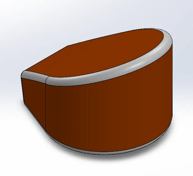
Oil tank is a component used to store the oil for cooling and lubrication purposes of engine components. Oil tanks can be of various kinds like engine oil tank, coolant oil tank, radiator oil tank, etc. The oil tank used in this American Chopper is used for engine lubrication and cooling. This tank is placed right below the rider seat on top of the gearbox.
TOOLS USED
- Sketch Tools:- 3 point arc, lines
- Feature:- extrude boss, fillet, combine, shell, appearance
COMBINE:- The Combine feature lives under Insert>Features>Combine. The common function allows you to add two bodies together, and keep the area that is common to them. To use this feature, we will select the common button, and then under Bodies to Combine, select the two bodies.
PEDAL
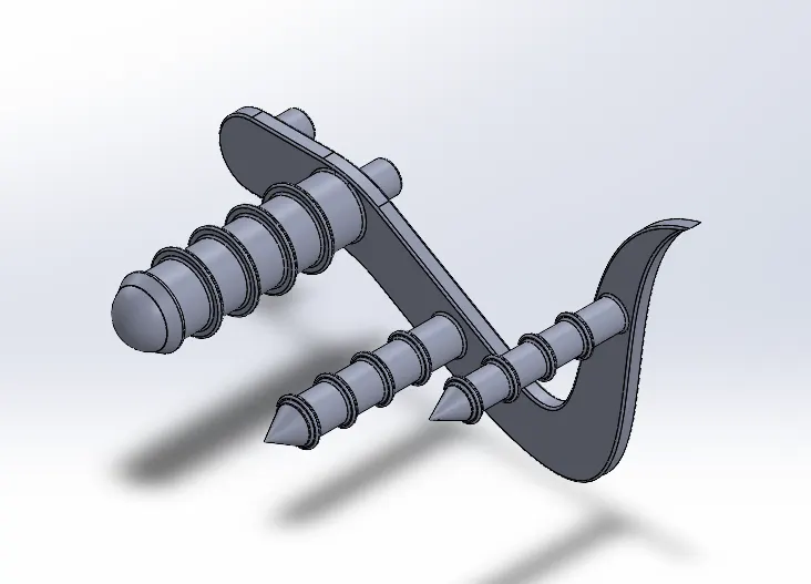
A pedal is a motorcycle component used by the rider to place their footon it while riding the bike. This is also called foot peg and is mounted on both sides of chassis. Its position depends on the type of motorcycle.
TOOLS USED
- Sketch Tools:- 3 point arc, line, spline, circle, sketch fillet
- Feature:- extrude boss, revolve, fillet, dome, chamfer, linear pattern, appearance
CHAMFER:- The chamfer tool creates a beveled feature on selected edges, faces, or a vertex. To create a chamfer: Click Chamfer (Features toolbar) or Insert > Features > Chamfer. Under Chamfer Parameters, select an item and set parameters.
LINEAR PATTERN:- Linear pattern features tool is a placed features tool which is used to create patterns of features in linear manner. For linear patterning, there is parent pattern (base pattern) which used to create the array of patterns in one or two dimension.
FRONT WHEEL
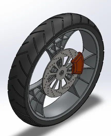
Motorcycle wheels are made to cope with radial and axial forces. They also provide a way of mounting other critical components such as the brakes, final drive and suspension. Wheels, and anything directly connected to them, are considered to be unsprung mass. Traditionally motorcycles used wire-spoked wheels with inner tubes and pneumatic tyres. Although cast wheels were first used on a motorcycle in 1927, it would not be until the 1970s that mainstream manufacturers would start to introduce cast wheels on their roadgoing motorcycles. Spoked wheels are usually made using steel spokes with steel or aluminium rims.
Front wheel of choppers are always larger than the rear wheel with narrow section as compared to the latter. The front wheel tyre in this american chopper has a narrow section meaning narrow surface contact.
TOOLS USED
- Sketch Tools:- 3 point arc, lines, spline, mid-point line, circle, sketch fillet, trim, extend, 3point centre rectangles
- Feature:- revolve boss, extrude boss, extrude cut, revolve cut, circular pattern, combine, fillet, chamfer, appearance
TRIM:-You can use Power trim to extend sketch entities along their natural paths. Extends or trims two sketch entities until they intersect at a virtual corner. Trims open sketch entities that lie inside two bounding entities. Trims open sketch entities outside of two bounding entities.To trim with the Power trim option: Right-click the sketch and select Edit Sketch. Click Trim Entities. (Sketch toolbar) or Tools > Sketch Tools > Trim.
EXTEND:-You can add to the length of a sketch entity (line, centerline, or arc). Use Extend Entities to extend a sketch entity to meet another sketch entity. To extend a sketch entity: In an open sketch, click Extend Entities.
REVOLVE CUT:-Revolved Cut command is generally used for the cutting material from a 3D geometry in Solidworks. It is working as Revolved Boss/Base but the difference is, it is used for cutting from 3D geometries in Solidworks. Also, there are other types of the feature of Revolved Cut in Solidworks.
REAR WHEEL
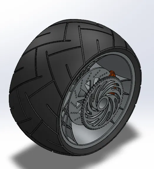
The back wheel is where most of the shifting and braking (for deceleration) will happen.Motorcycle wheels are made to cope with radial and axial forces. They also provide a way of mounting other critical components such as the brakes, final drive and suspension. Wheels, and anything directly connected to them, are considered to be unsprung mass. Traditionally motorcycles used wire-spoked wheels with inner tubes and pneumatic tyres. Although cast wheels were first used on a motorcycle in 1927, it would not be until the 1970s that mainstream manufacturers would start to introduce cast wheels on their roadgoing motorcycles. Spoked wheels are usually made using steel spokes with steel or aluminium rims. Cast wheels are predominantly made from an aluminium-alloy, but can also be made from more-exotic materials, such as magnesium content alloy or carbon fibre.
TOOLS USED
- Sketch Tools:- 3 point arc, lines, spline, mid-point line, circle, sketch fillet, trim, extend, 3point centre rectangles
- Feature:- revolve boss, extrude boss, extrude cut, revolve cut, circular pattern, combine, fillet, chamfer, appearance
FRONT FORK
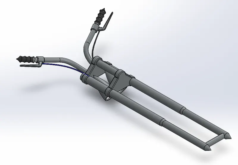
A motorcycle fork connects a motorcycle's front wheel and axle to its frame, typically via a yoke, also known as a triple clamp, which consists of an upper yoke joined to a lower yoke via a steering stem, a shaft that runs through the steering head, creating the steering axis. Most forks incorporate the front suspension and front brake, and allow the front wheel to rotate about the steering axis so that the bike may be steered. Most handlebars attach to the top clamp in various ways, while clip-on handlebars clamp to the fork tubes, either just above or just below the upper triple clamp.
The fork and its attachment points on the frame establish the critical geometric parameters of rake and trail, which play a major role in defining how a motorcycle handles and dives during braking.[1] While the standard telescopic fork arrangement is found with few major differences among mainstream street motorcycles since the 1970s, historically there have been many variations, including trailing or leading link, springer, Earles, girder, and others, as well as non-fork steering such as hub-center steering.
TOOLS USED
- Sketch Tools:- 3 point arc, spline, lines, circle, trim
- Feature:- revolve boss, extrude boss, revolve cut, extrude cut, linear pattern, dome, body move/copy, curves projected, sweep, reference geometry- plane, combine, mirror, fillet, chamfer, appearance
BODY MOVE:-In multibody parts, you can move, rotate, and copy solid and surface bodies, or place them using mates. To move, copy, rotate, or mate a solid or surface body: Click Move/Copy Bodies (Features toolbar) or Insert > Features > Move/Copy.
CURVES PROJECTED:-You can project a sketched curve onto a model face to create a 3D curve. You can also create a 3D curve that represents the intersection of two extruded surfaces generated by creating sketches on two intersecting planes.
SWEEP:-Sweep features are defined by using custom 2D cross-section (or face) moved along a pre-set path to create a 3D shape or surface. With the sweep method, the user defines a 2-D or 3-D guide curve, in addition to creating the cross-section.
REFERENCE GEOMETRY:- Reference geometry defines the shape or form of a surface or a solid. Reference geometry includes items such as planes, axes, coordinate systems, and points. You can use reference geometry in the creation of several kinds of features. For example: Planes are used in lofts and sweeps.
CHASSIS
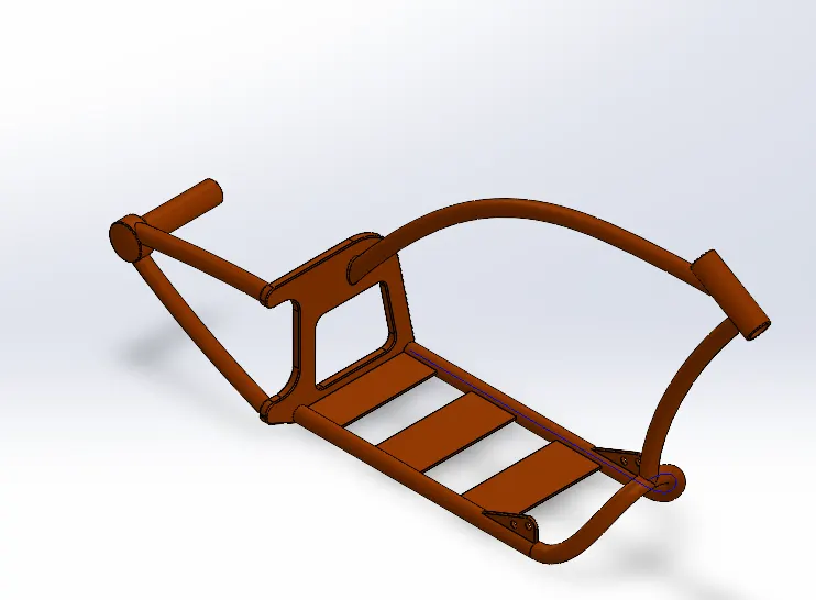
Chassis for a car is analogous to the skeleton for a human body. Chassis, also known as 'Frame', is the foundation structure of any car that supports it from underneath. The purpose of the chassis is to bear the weight of the car in its idle and dynamic states.
TOOLS USED
- Sketch Tools:- sketch picture, spline, lines, circle, trim
- Feature:- extrude boss, extrude cut, revolve, dome, curve projected, split, sweep, reference geometry, mirror, combine, fillet, chamfer, appearance
ENGINE
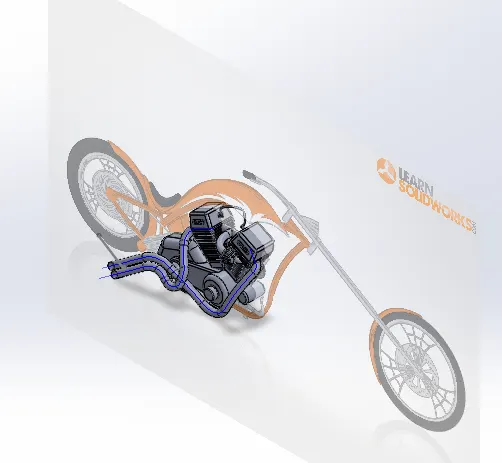
A motorcycle engine is an engine that powers a motorcycle. Motorcycle engines are typically two-stroke or four-stroke internal combustion engines, but other engine types, such as Wankels and electric motors, have been used. Most engines have a gearbox with up to six or even 7 ratios. Reverse gear is occasionally found on heavy tourers, for example the Honda GL1600, and sidecar motorcycles, such as the Ural. The rider changes gears on most motorcycles using a foot-pedal and manual clutch, but early models had hand-levers. More recently, some have automatic or semi-automatic gearboxes, and some using CVT transmission.
TOOLS USED
- Sketch Tools:- sketch picture, line, spline, circle, circular sketch pattern, construction line, 3 point center rectangle, trim
- Feature:- extrude boss, extrude cut, revolve, dome, curve projected, composite curves, split, sweep, reference geometry, circular pattern, linear pattern, mirror, combine, fillet, chamfer, appearance
COMPOSITE CURVES:- You can create composite curves by combining curves, sketch geometry, and model edges into a single curve. Use a composite curve as a guide curve when creating a loft or a sweep.
GASTANK
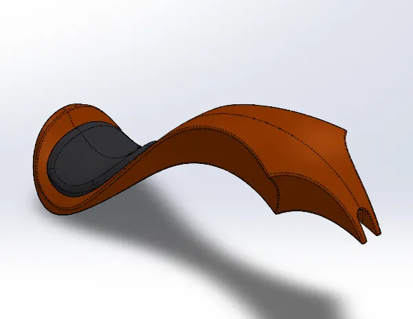
A fuel tank (also called a petrol tank or gas tank) is a safe container for flammable fluids. Though any storage tank for fuel may be so called, the term is typically applied to part of an engine system in which the fuel is stored and propelled (fuel pump) or released (pressurized gas) into an engine. Fuel tanks range in size and complexity from the small plastic tank of a butane lighter to the multi-chambered cryogenic Space Shuttle external tank.
Typically, a fuel tank must allow or provide the following:
- Storage of fuel: the system must contain a given quantity of fuel and must avoid leakage and limit evaporative emissions.
- Filling: the fuel tank must be filled in a secure way, without sparks.
- Provide a method for determining level of fuel in tank, gauging (the remaining quantity of fuel in the tank must be measured or evaluated).
- Venting (if over-pressure is not allowed, the fuel vapors must be managed through valves).
- Feeding of the engine (through a pump).
- Anticipate potentials for damage and provide safe survival potential.
TOOLS USED
- Sketch Tools:- sketch picture, line, spline, construction line, trim
- Feature:- surface sweep, surface loft, surface trim, boundary surface, surface knit, surface extrude, curves, projected curves, split line, sweep cut, reference geometry, mirror, shell, fillet, appearance
SURFACE SWEEP:- Sweep Surfaces are surfaces that are generated from a section curve positioned along a path. Various Sweep types are available to extend the sweep definition as follows: Sweep by Two Guide Curves is defined as moving and adjusting a section curve along two guide curves.
SURFACE LOFT:-The loft feature is an important tool for (surface) modeling in SolidWorks. The loft feature creates a shape by making transitions between multiple profiles and guide curves. This tool is very valuable for modeling complex surfaces. You can do some really cool stuff when you use this feature properly.
BOUNDARY SURFACE:-A boundary surface is defined to be either the mathematical envelope between a charged region and empty space, where the density fields associated with the region vanish, or the mathematical envelope between two electrically different regions in contact, where the density fields associated with the two change abruptly.
SURFACE KNIT:-Use the Knit Surface tool to combine two or more faces and surfaces into one. Note the following about knit surfaces: Edges of the surfaces must be adjacent and not overlapping. Surfaces do not need to be on the same plane. Select the entire surface body, or select one or more adjacent surface bodies.
SURFACE EXTRUDE:-You can create extruded surfaces from models that include 2D or 3D faces and knit the extruded surfaces to surrounding features. Click Insert > Surface > Extrude. Select a face: To extrude from a 3D face, select a 3D face. To extrude from a 2D face, press Alt + select the planar face.
SURFACE TRIM:-A trimmed surface has two parts: a surface that underlies everything and defines the geometric shape, and trimming curves that mark sections of the underlying surface that are trimmed away. Trimmed surfaces are created with commands that trim or split surfaces with curves and other surfaces.
ASSEMBLY
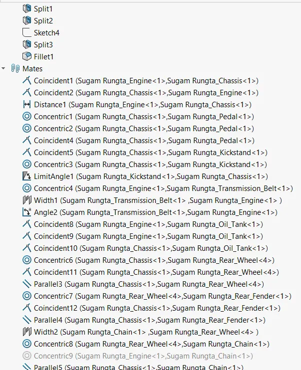
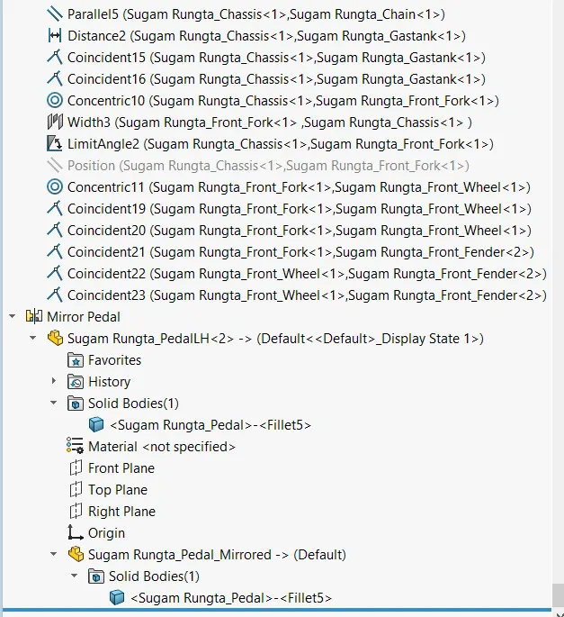
The assembly of the chopper consists of all the parts attached in appropriate manner with appropriate mates. the main component chassis is first fixed and then other components are mated to their correct positions.
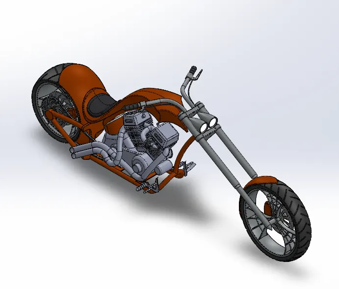
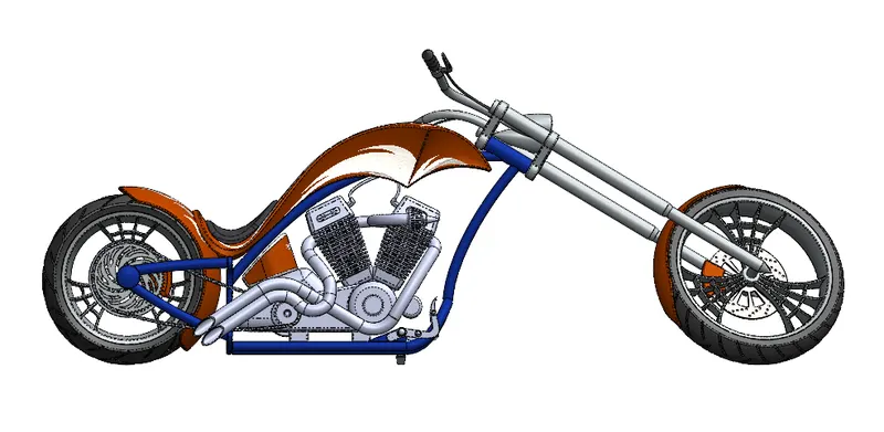
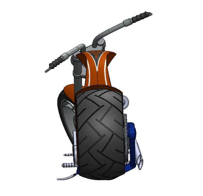
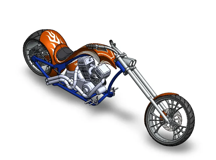
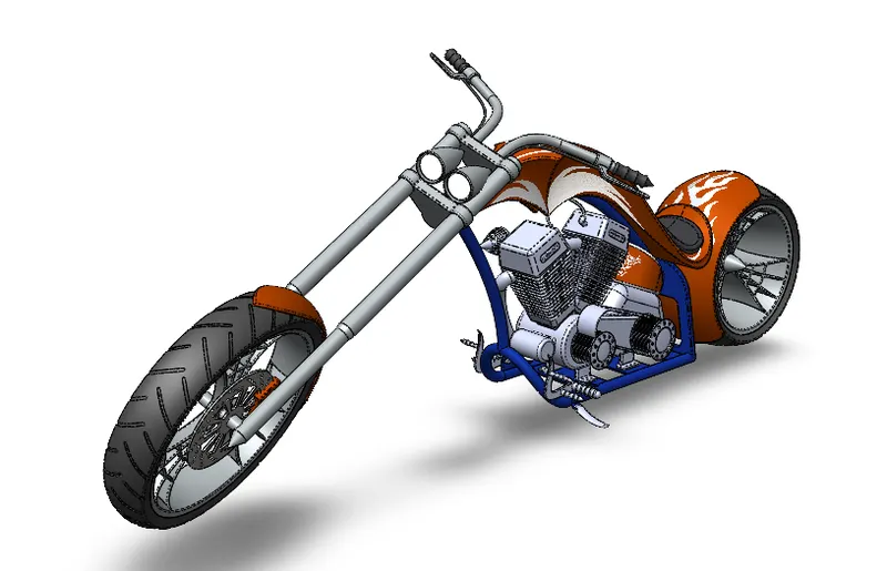
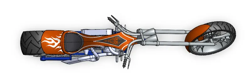
Mates are constraints that hold components together in SOLIDWORKS assemblies. Like relations in sketches, they are geometric conditions relating one entity to another. Each Mate requires you to select two (or more) faces, edges, or vertices on separate parts to build a constraint holding those parts together.
Access the Mate dialog by clicking the Mate button in the assembly tab of the CommandManager. The paper clip (shown below) is the standard SOLIDWORKS symbol for mates; any time you see it, you're dealing with mates.
There are several different types of Standard Mates in SOLIDWORKS:
- Coincident
- Parallel
- Perpendicular
- Tangent
- Concentric
- Angle
- Lock
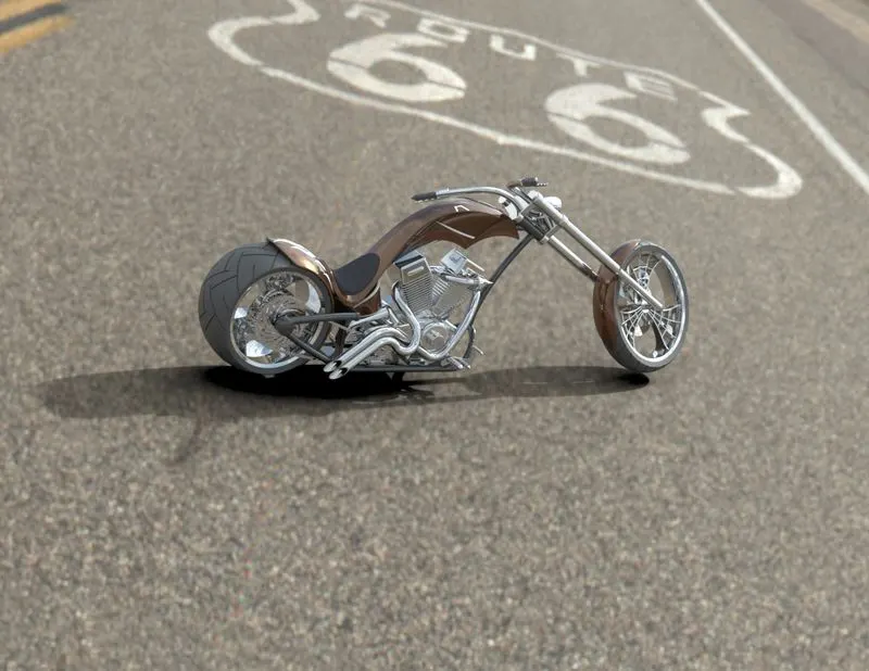
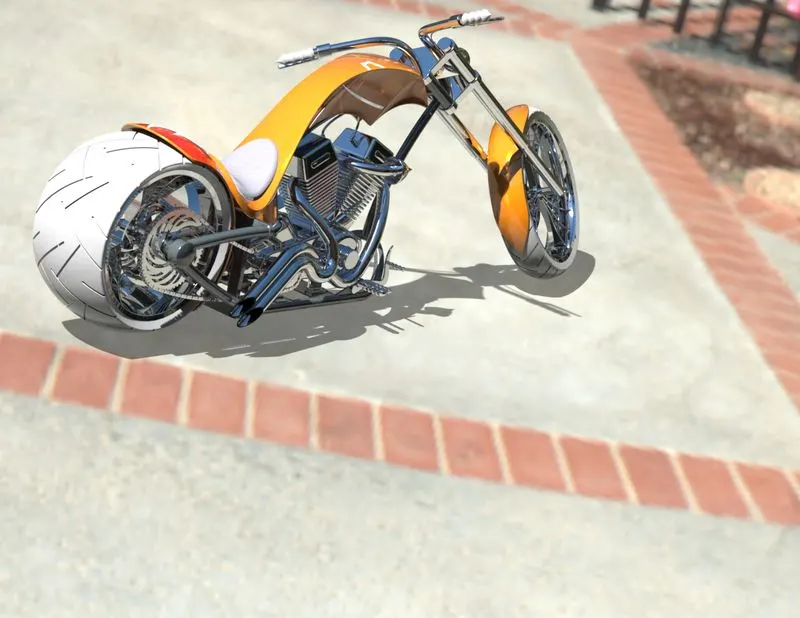
RENDERING WITH PHOTOVIEW 360
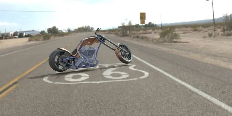
PhotoView 360 is a SolidWorks add-in that produces photo-realistic renderings of SolidWorks models. The rendered image incorporates the appearances, lighting, scene, and decals included with the model. PhotoView 360 is available with SolidWorks Professional or SolidWorks Premium.
WORKFLOW
- With a model open, click Tools > Add-In and add in PhotoView 360.
- Start a preview in the graphics area or open the Preview window to see how changes you make to the model affect the rendering.
- Edit appearances, the scene, and decals.
- Edit lights.
- Edit PhotoView Options.
- When you are ready, perform a final render either now (PhotoView > Final Render) or later (PhotoView > Schedule Render).
- Make detailed adjustments in the Final Render Window.
SOLIDWORKS VISUALIZE
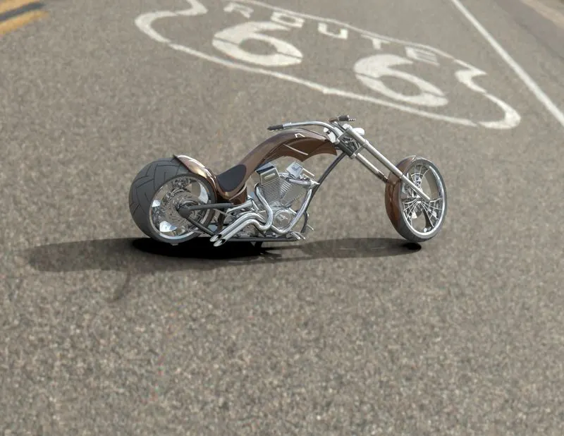
SOLIDWORKS Visualize is a photo-realistic rendering tool that utilizes your CAD data to create magazine quality images or commercial quality animations. Make your images pop with real-time ray tracing, AI Denoiser, and I-Ray technology from Nvidia powered GPU’s or AMD ProRender.
Visualize has two different packages: Standard and Professional. The great news is that if you purchase SOLIDWORKS CAD Professional or Premium and you are on maintenance, then you have Visualize Standard already! Get your renders started by following the introductory training videos in the GoEngineer Resource Center.
Visualize Professional adds an array of features including animations, custom lighting, VR, 360 Interactive, and much more. SOLIDWORKS Visualize Professional provides the highest level of detail and optimized render times.
CONCLUSION
Design, Assembly & Photorealistic Rendering using Solidworks was completed successfully.