Photo Realistic Rendering
DESIGNING AN AMERICAN CHOPPER ON SOLIDWORKS
OBJECTIVE
To design and assemble an American Chopper using SolidWorks and render the model using PhotoView 360 and SolidWorks Visualise.
INTRODUCTION
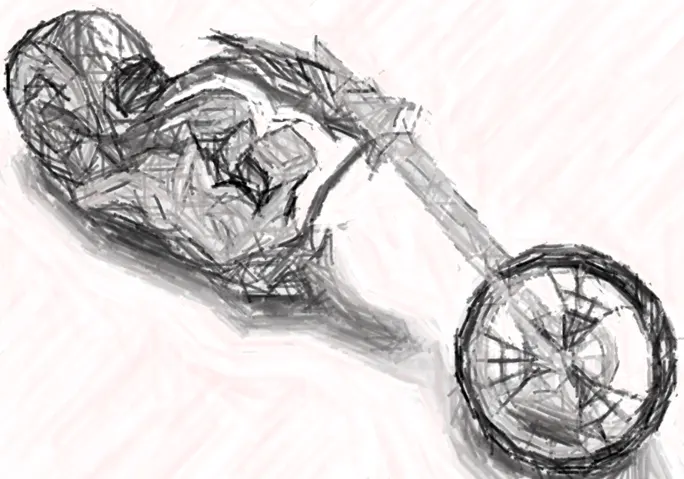
Choppers are the type of motorcycles that have been chopped down to the bare minimum, by removing all the unnecessary parts and only keeping the ones that are required to make it go. People would even strip down the complete bike, fabricate new exhaust pipes, gas tanks by chopping off or removing the existing parts to make it stand out and be unique, hence the name Chopper. These were first introduced in California somewhere around the 1950s, shortly after World War 2, when the Veterans used to buy and then modify these bikes as per their liking.
This category of bikes was mass popularized by one of the most renowned names in the biking industry, Harley Davidson, which began to offer mass-manufactured custom bikes based on the most popular chopper designs during the 1980s.
I have designed a Cosmetic model of the American Chopper to understand various features of SolidWorks and the rendering software used.
DESIGN METHODOLOGY
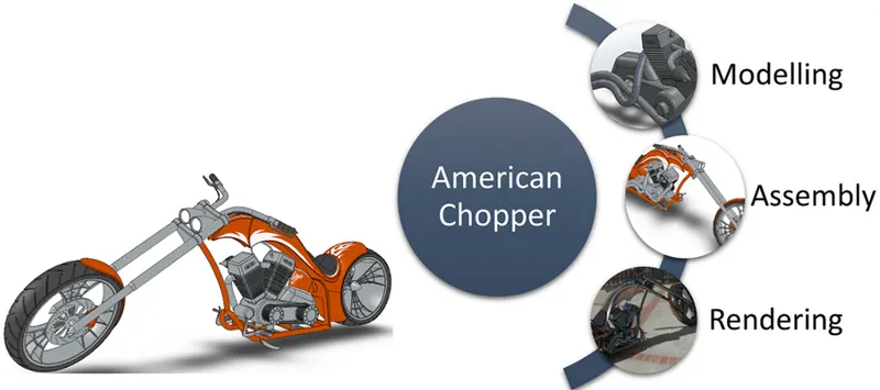
To design the American Chopper, I will first model each individual part of the chopper and then assemble them together to create a final product. This final product will then be set up in multiple environments to give photo-realistic images of the chopper.
During the process, I have modelled the following parts:
- Transmission Belt
- Kickstand
- Front Fender
- Rear Fender
- Chain
- Oil Tank
- Pedal
- Front Wheel
- Rear Wheel
- Front Fork
- Chassis
- Engine
- Gas Tank
DESCRIPTION
- Transmission Belt
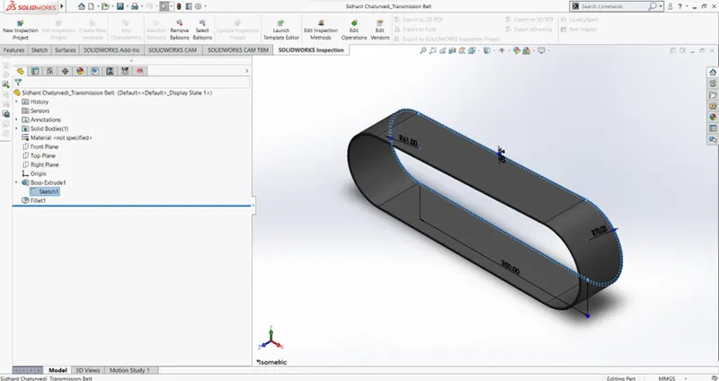
To model the transmission belt, I first created a sketch using lines and arcs. I used Offset Entities to complete the sketch.
This sketch was then extruded, and some fillets were applied to the outer edge of it.
I have given it a matt rubber finish.
- Kickstand
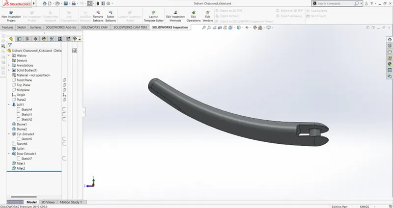
To model this part, I used some additional features apart from the Boss Extrude.
We used Loft to create a lofted surface between two sketches while following a sketched path to create the main body of the kickstand.
I then used the Dome feature on the two ends of the kickstand to give it a nice and complete look.
I then used the Cut Extrude feature to remove some material from one end of the kickstand to create a space where a mounting point can be created to mount the kickstand onto the chassis.
After that, on the opposite end, I used the split feature with consume cut bodies turned on to create a flat spot underneath for the kickstand to rest.
And finally, I did a Mid Plane Extrude to create the mounting point for the kickstand and finished off the part by giving some final fillets inside the cut extruded part.
I have given the kickstand a Chrome finish.
- Front and Rear Fender
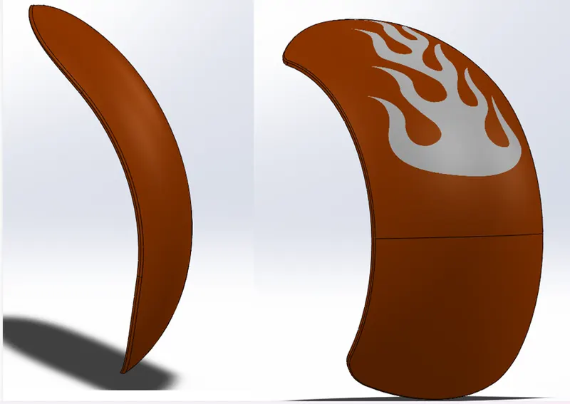
To model the front and rear fenders, Revolved Boss was used in conjugation with the Split feature.
Revolved Boss was used to create the fender out of the sketch and the Split tool (with consume cut bodies turned on) was used to cut some of the material from the ends of the fender. The parts were completed by finally applying some fillets to the outer edges and giving it a Metal Painted appearance with Siena as the colour.
- Chain
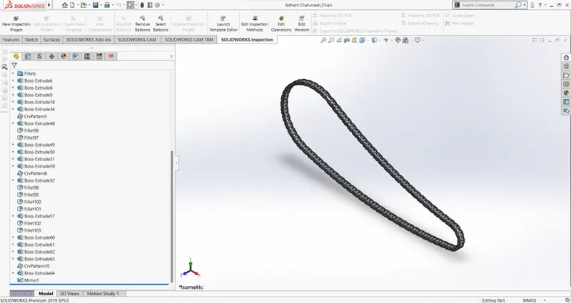
To model the chain, we used some additional features of SolidWorks apart from the ones that have already been used above. I created some blocks for the chain links and the pins which were first Boss Extruded and then patterned onto a path using a curved drive pattern. This was done in phases to make sure that the links align properly at every curve intersection.
After completing the complete path, we then mirrored only the chain links and not the pins to complete the chain.
Then finally, I applied a Metal Painted Chrome finish onto the chain.
This finish has been changed in some renders as you’ll see while going further.
- Oil Tank
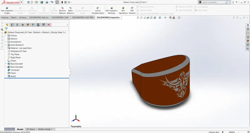
To create the oil tank, I used two different Boss Extruded sketches and combined them using the Combine feature. This was done to give the tank a curved front while having a sloped top simultaneously.
Since it is a Tank, the solid body had to be hollow. I used the shell feature on the tank to create a hollow tank with a wall thickness of 3mm.
Then the same Siena finish that we used before was applied to it along with white fillets to give it a more appealing look.
- Pedal
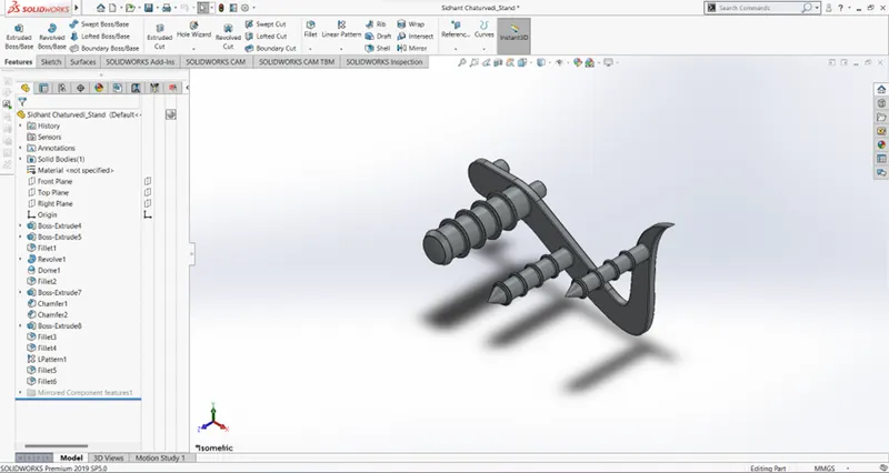
To Model the Pedal, we used Extruded Boss Base to create the mainframe for the Pedal. Two Pins were also Boss Extruded after this to create the mounting points for the pedal. 01 mm Fillet was applied to the outer edges of the mainframe after this.
To create the footrest of the pedal, I first selected the top plane and drew a sketch. I used Revolved Boss on this sketch to create a solid body for the footrest.
A dome was applied to its end followed by 01mm Fillets at the ends of the mounting pin and the footrest.
Now, using the first Sketch that I had created for the mainframe of the Pedal, I Boss Extruded two more pins equal to the length of the footrest. I then applied Chamfer to the ends of both these pins to give it a conical head.
For the concentric circles on these three bodies (2 long pins with conical head + footrest), I created another sketch using convert entities and offset entities. This sketch was then Boss extruded, and fillet was applied to it before using a Linear pattern on it. This was then patterned on all three bodies to give it the final look.
Finally, after applying some more fillets and giving it a metal painted chromium finish, the part was completed.
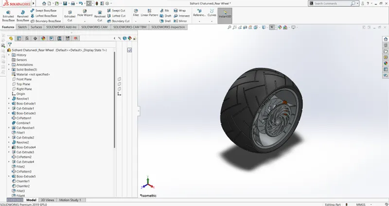
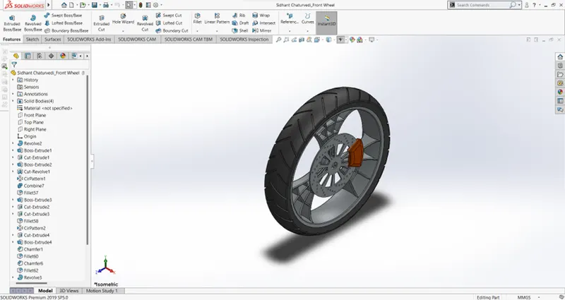
- Front and Rear wheel
Both the front and the rear wheel had a very similar process of design since both the parts are fundamentally the same except for the dimensions.
To start off, I first created the axle and the rim of the wheel. I used Revolved Boss for this. Now, to create the spokes, we again drew a new sketch on our right plane and boss extruded it. This boss was then Cut extruded using a new sketch which was created on the Boss itself. We then created a new sketch for the spider web design on the wheels and Boss extruded it. We then used a circular pattern on this spoke to pattern it throughout the wheel. I then combined all the bodies together by using add. Now, to give the wheels a deep-dish look, I created a new sketch to cut revolve the wheel and give it the appropriate look. I then applied some fillets to the edge of the spokes to finish off the rim and moved on to the axle.
For the axle, the first thing that I had to do was to cut out a hole in the axle for the wheel to be mounted on the chassis. For this I simply used convert entities and offset entities to create a new sketch which was the cut extruded to hollow out the axle. I then created a new sketch and revolved it to create the complete axle.
The next thing I had to do was to create the rotors for the brakes. For this, we first created a sketch of two concentric circles and Boss extruded it. This gave us the rotor without any details. To create the details, we again drew some new sketches on the rotor and used cut extrude and circular patterns to achieve the result.
I then added the brake calliper to the rotor by drawing a new sketch on the rotor and performing a mid-plane boss extrude. To finish it off, we applied some chamfers and fillets to it and gave it a metal painted sienna finish.
We moved on to our next section of the wheel which is the sprocket. To create the sprocket, we took one end of our axle shaft and used convert entities on the larger diameter. We then again drew one larger circle keeping the same centre and performed a Boss Extrude. We applied Chamfer to the outer edge of the extruded surface. Then, for the teeth of the sprocket, I drew a new sketch and performed cut extrude with it. We applied some fillets to the teeth obtained and patterned them circularly around the sprocket.
We followed the same technique to give slots on the rotor. This completed the rotor and we then moved on to our final part, which is the tire.
I used the revolved base feature to create the tire and then used cut extrude and circular pattern to draw out treads across the tire.
We finally gave the tire a Matt Rubber appearance to finish off the part.
- Front Fork
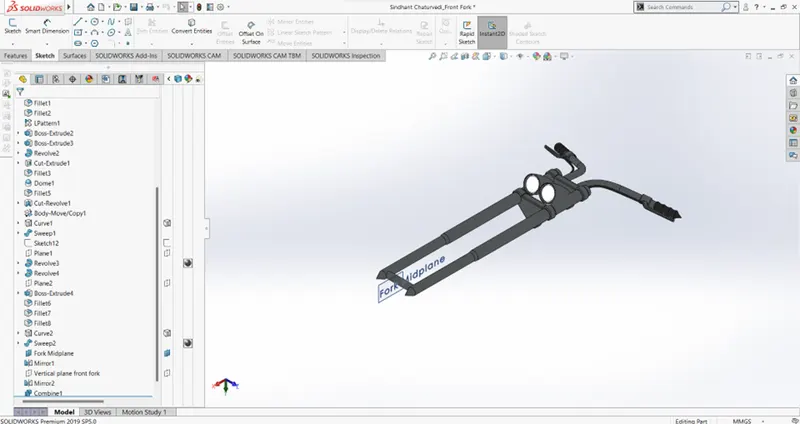
For the front fork, apart from the features already used above, we used some new features like projected curves and swept boss/base to create the complex curves on the handle and on the wires coming from the handle. We created some additional planes as well.
I modelled only the half fork first and then mirrored it across.
We applied an area light appearance to the headlights and finished off by giving the fork a metal painted chromium and giving the wires and the handle a gloss rubber finish.
- Chassis
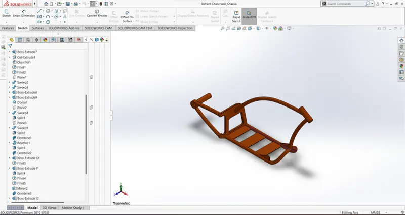
For the Chassis, we used some additional features apart from the ones already talked about above. We used the split feature to cut out some material and split the two coinciding solid bodies as per the design requirements. We created projected curves to create the hollow cylindrical base of the chassis and then mirrored it across.
The chassis was finally completed by giving it a metal painted Sienna finish.
10. Engine
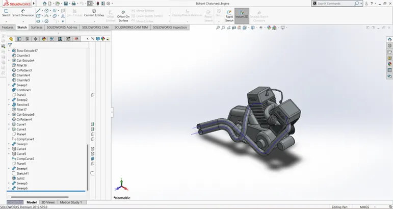
For the engine, we used the Linear pattern and a lot of already used features. One new feature that I used here was Composite curves which were used to model the exhaust pipes of the engine. The complete engine was given a metal painted chromium finish.
11. Gas Tank
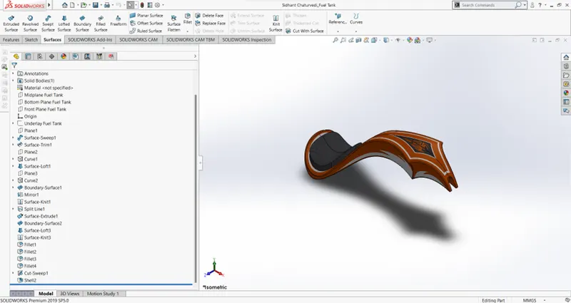
To model the gas tank, we used the surface features of SolidWorks. I used Swept surface, Lofted surface, and boundary surface in conjugation with features I have already mentioned before in this report to model the gas Tank. I also used the knit surfaces option to knit multiple surfaces together seamlessly.
To finish off the part, I gave it a metal painted sienna finish and applied some decals.
ASSEMBLY
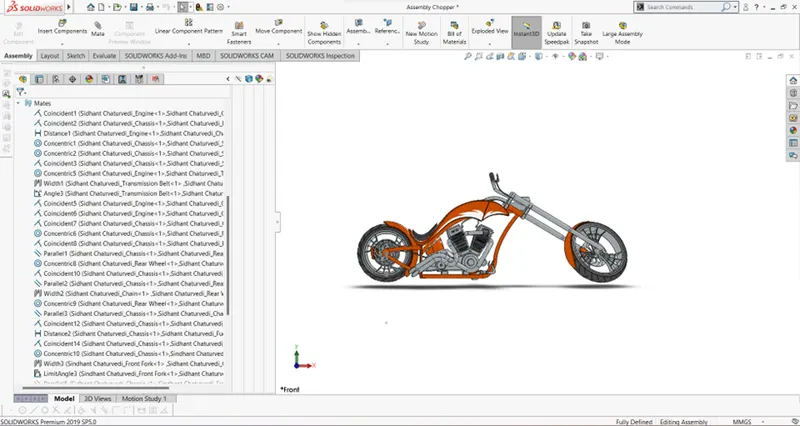
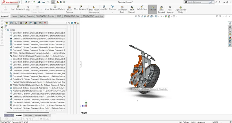
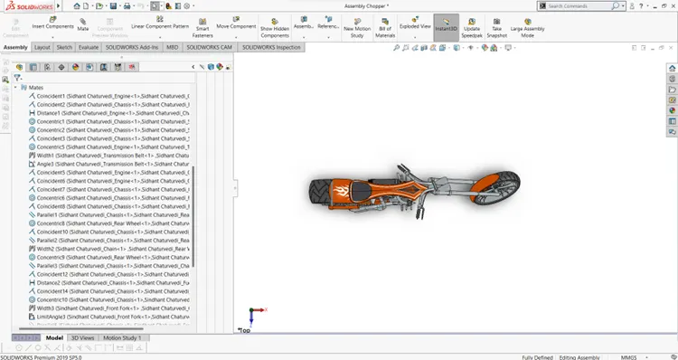
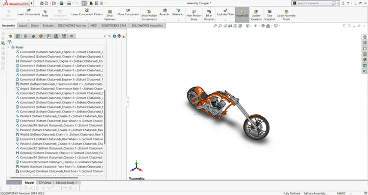
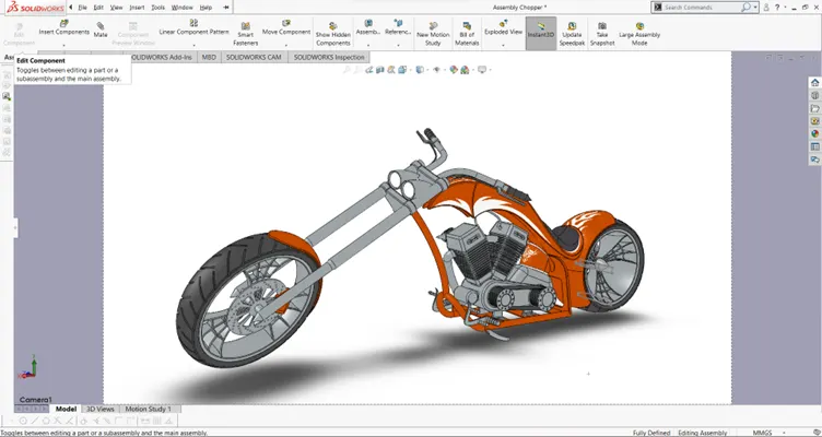
After modelling all the parts, I created an assembly file and assembled all the parts together. I used standard mates like concentric mates, tangent mates, parallel mates etc. in conjunction with some advanced mates like width mate.
RENDER
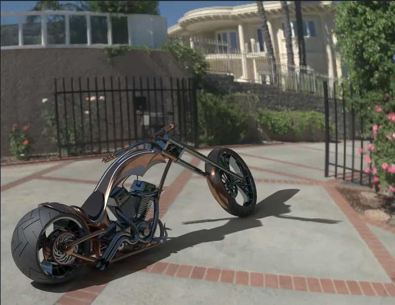
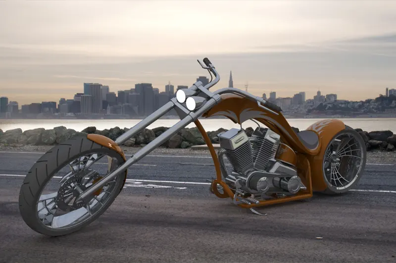
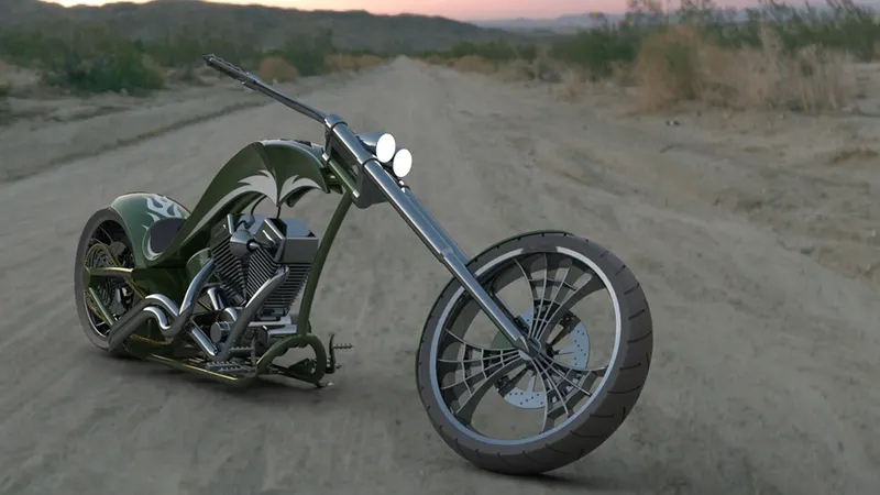
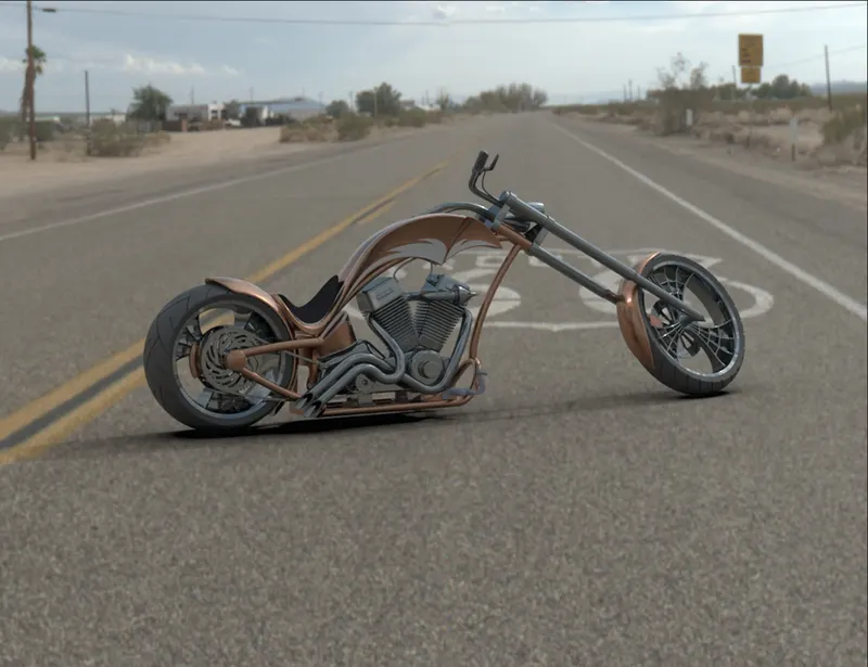
To render the model, I have used PhotoView360 and SolidWorks Visualize.
I adjusted the environment, added different backgrounds and cameras, and even adjusted the lights in some renders to bring out the photo-realistic version of the chopper. With some renders, I have even changed the appearance of some parts like the chain and the handle to create multiple variants of the same model and test out how different colour combinations would look on the chopper.
CONCLUSION
Designing, Assembly and Rendering of the cosmetic model of the American Chopper is complete