Design, Assembling, Modelling and Photo Realistic Rendering of American Chopper
Design, Assembling, Modeling and Photo Realistic Rendering of American Chopper
Introduction:
SolidWorks is a solid modeling computer-aided design (CAD) and computer-aided engineering (CAE) computer program that runs primarily on Microsoft Windows. While it is possible to run SolidWorks on MacOS, it is not supported by SolidWorks. SolidWorks is published by Dassault Systèmes.
SOLIDWORKS is used to develop mechatronics systems from beginning to end. At the initial stage, the software is used for planning, visual ideation, modeling, feasibility assessment, prototyping, and project management. The software is then used for design and building of mechanical, electrical, and software elements.
Objective:
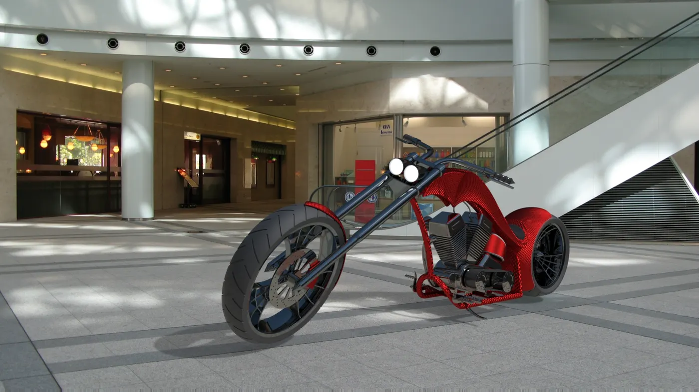
The main aim of this project is to sketch and build a complete road-ready Harley Davidson bike using SolidWorks and to create a photo-realistic rendering with real time appearance and view.
Design Methodology:
SolidWorks is a parasolid-based solid modeler, and utilizes a parametric feature-based approach to create models and assemblies.
Parameters refer to constraints whose values determine the shape or geometry of the model or assembly. Parameters can be either numeric parameters, such as line lengths or circle diameters, or geometric parameters, such as tangent, parallel, concentric, horizontal or vertical, etc. Numeric parameters can be associated with each other through the use of relations, which allows them to capture design intent.
Design intent is how the creator of the part wants it to respond to changes and updates. For example, you would want the hole at the top of a beverage can to stay at the top surface, regardless of the height or size of the can. SolidWorks allows you to specify that the hole is a feature on the top surface, and will then honor your design intent no matter what the height you later gave to the can.
Features refer to the building blocks of the part. They are the shapes and operations that construct the part. Shape-based features typically begin with a 2D or 3D sketch of shapes such as bosses, holes, slots, etc. This shape is then extruded or cut to add or remove material from the part. Operation-based features are not sketch-based, and include features such fillets, chamfers, shells, applying draft to the faces of a part, etc.
screen shot captured from a SolidWorks top-down design approach.
Building a model in SolidWorks usually starts with a 2D sketch (although 3D sketches are available for power users). The sketch consists of geometry such as points, lines, arcs, conics (except the hyperbola), and splines. Dimensions are added to the sketch to define the size and location of the geometry.
Relations are used to define attributes such as tangency, parallelism, perpendicularity, and concentricity. The parametric nature of SolidWorks means that the dimensions and relations drive the geometry, not the other way around. The dimensions in the sketch can be controlled independently, or by relationships to other parameters inside or outside of the sketch.
SolidWorks pioneered the ability of a user to roll back through the history of the part in order to make changes, add additional features, or change the sequence in which operations are performed.Later feature-based solid modeling software has copied this idea.
In an assembly, the analog to sketch relations are mates. Just as sketch relations define conditions such as tangency, parallelism, and concentricity with respect to sketch geometry, assembly mates define equivalent relations with respect to the individual parts or components, allowing the easy construction of assemblies. SolidWorks also includes additional advanced mating features such as gear and cam follower mates, which allow modeled gear assemblies to accurately reproduce the rotational movement of an actual gear train.
Finally, drawings can be created either from parts or assemblies. Views are automatically generated from the solid model, and notes, dimensions and tolerances can then be easily added to the drawing as needed.
Flow diagram of this project
Skectching of different parts required for american chopper >>> Adding materials to parts which are required based on the material and holding capabality >>> Assembling the different parts based on their location and comfort of driving >>> Applying the decals to the gastank, oil tank and fenders >>> setting up the camera to its position >>> visuvalize the bike for it suitable location.
Different Parts in chopper:
- Transmission belt
- Front fender
- Rear fender
- Chain
- Side stand
- Pedal
- Front wheel
- Rear wheel
- Engine
- Chassis
- Front fork
- Oil tank
Description of the parts:
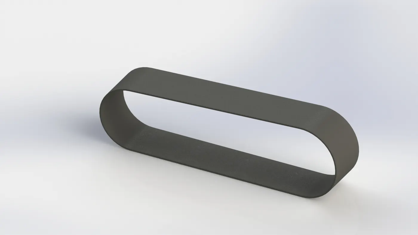
Transmission belt:
The main function of the transmisson belt is to transfer the power from engine to rear wheel.
A belt is a loop of flexible material used to link two or more rotating shafts mechanically. Belts may be used as a source of motion, to transmit power efficiently or to track relative movement. Belts are looped over pulleys and may have a twist between the pulleys, and the shafts need not be parallel. Some of the important tools used to model belt line, offset, adding relations such as tangency, extrude etc.
Fenders:
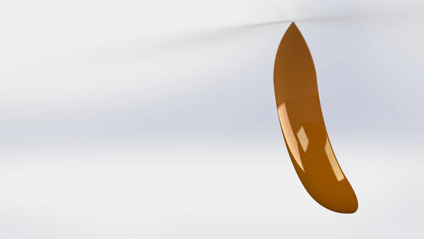
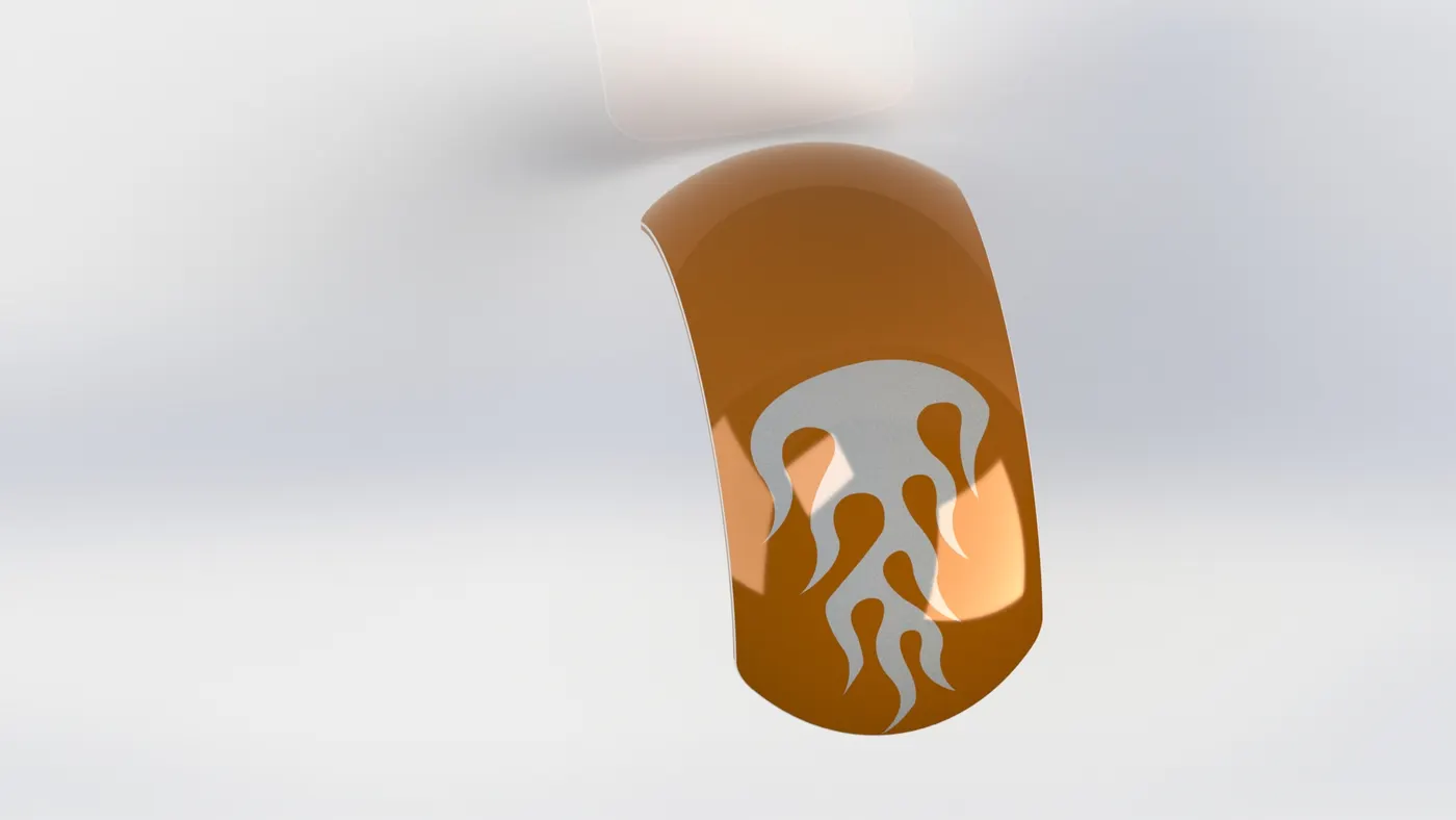
Main purpose of the fenders is to protect the driver from dust etc.
Fender is the American English term for the part of an automobile, motorcycle or other vehicle body that frames a wheel well (the fender underside). Its primary purpose is to prevent sand, mud, rocks, liquids, and other road spray from being thrown into the air by the rotating tire. Fenders are typically rigid and can be damaged by contact with the road surface.
Sticky materials, such as mud, may adhere to the smooth outer tire surface, while smooth loose objects, such as stones, can become temporarily embedded in the tread grooves as the tire rolls over the ground. These materials can be ejected from the surface of the tire at high velocity as the tire imparts kinetic energy to the attached objects. For a vehicle moving forward, the top of the tire is rotating upward and forward, and can throw objects into the air at other vehicles or pedestrians in front of the vehicle. Some of the important tools to model the fenders are trim, revolve, split etc.,
Front fender
Rear fender
Chain:
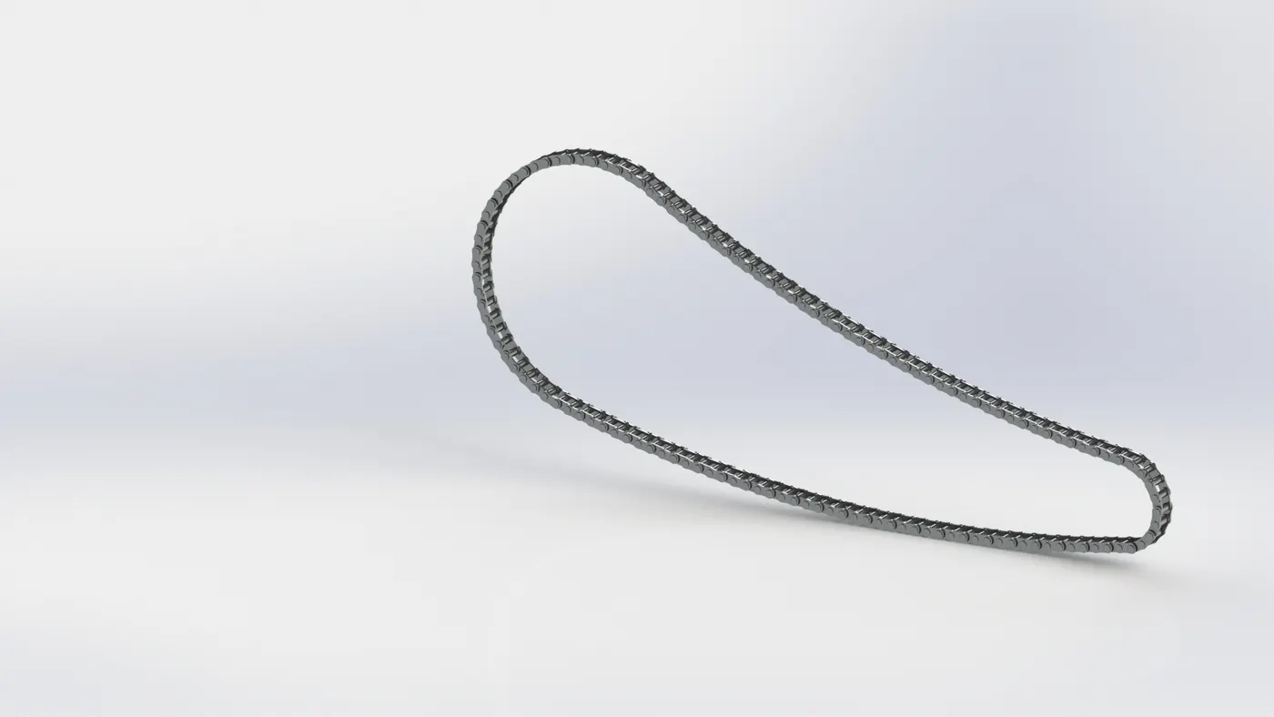
A chain is a serial assembly of connected pieces, called links, typically made of metal, with an overall character similar to that of a rope in that it is flexible and curved in compression but linear, rigid, and load-bearing in tension. A chain may consist of two or more links.Check for excessive slack in the drive chain. It is dangerous to drive with a loose chain, as it could get out of the drive gear and become entangled with the rear wheel and could cause it to fall off your motorcycle. The slack in the chain should not be more than 20 mm. Some of the important tools to model the chain are line, circle, circular patterns, creating blocks, coincide, tangency, concentric, extrude, fillets, etc.
Side stand or kick stand:
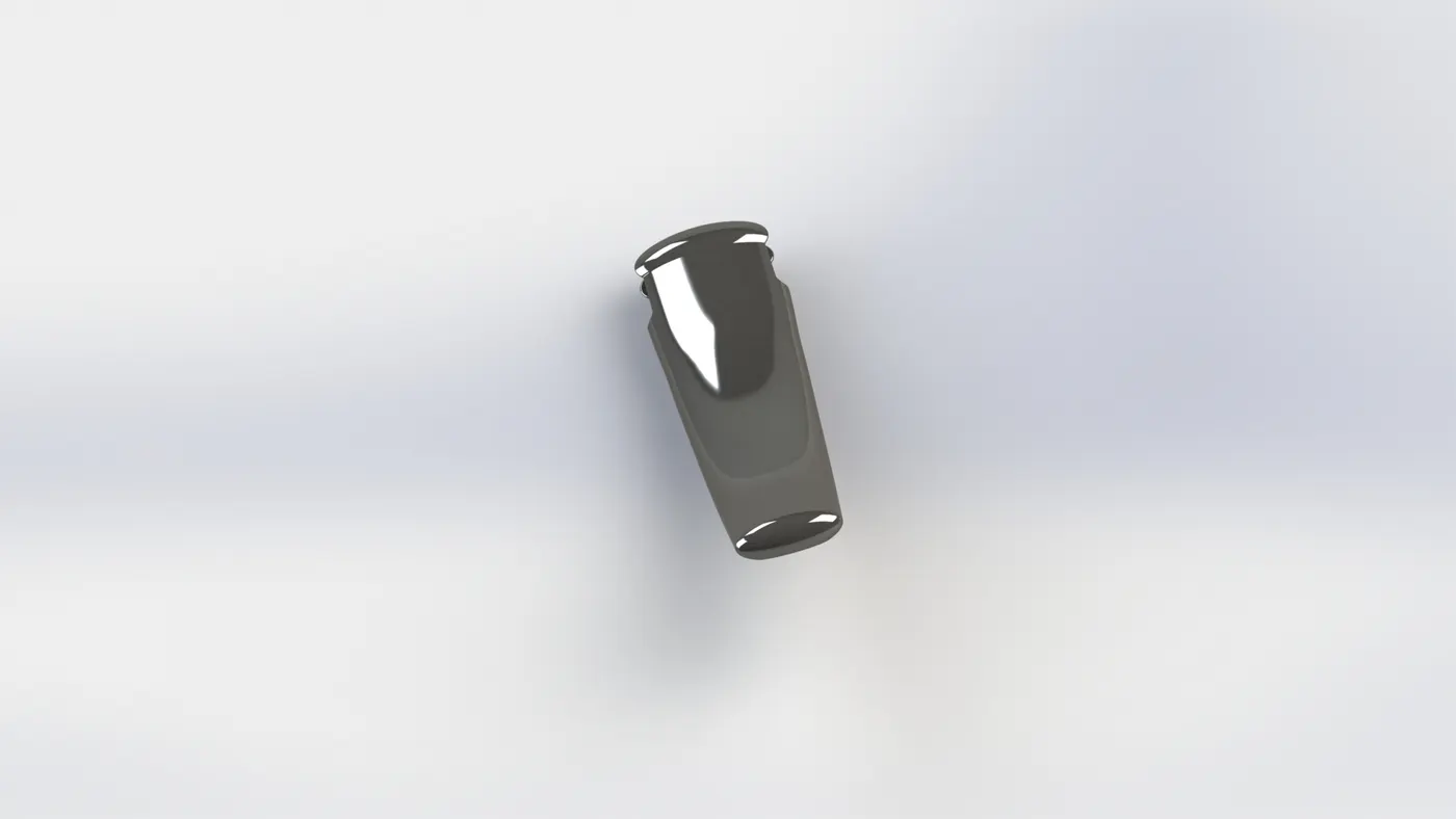
A kickstand is a device on a bicycle or motorcycle that allows the bike to be kept upright without leaning against another object or the aid of a person. A kickstand is usually a piece of metal that flips down from the frame and makes contact with the ground. It is generally located in the middle of the bike or towards the rear. Some of the important tools required to model the kick stand are boss extrude, pierce, dome , cut extrude, split,etc.,
Pedal:
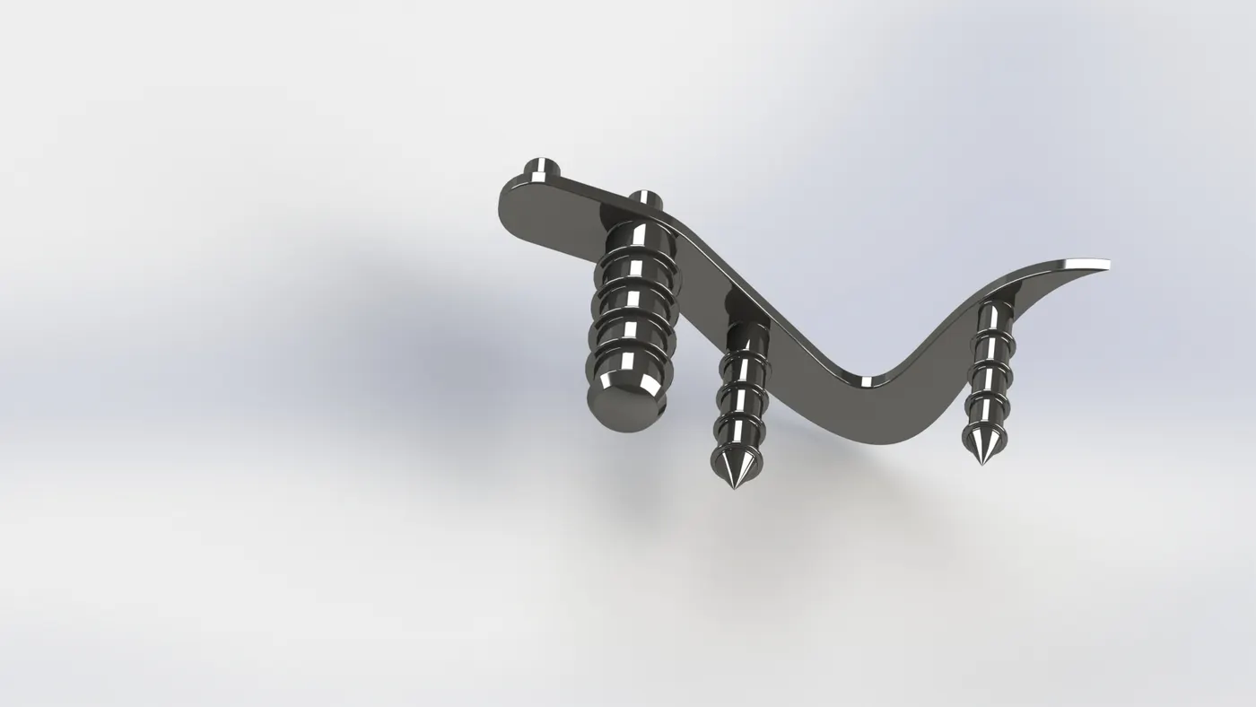
The purpose of the foot pedal is to keep the foot as flexible to change the gears with left foot and operate the brake through right pedal.
Rear wheel:
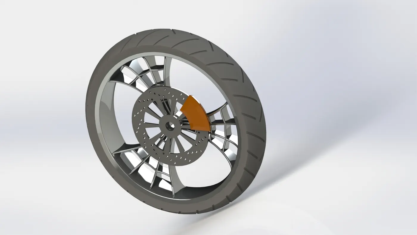
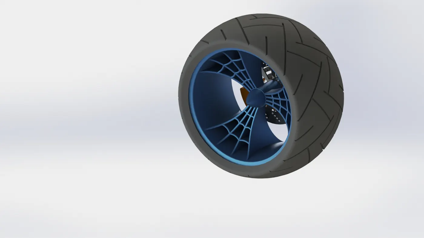
Rear wheel is the important wheel in the motor cycle is to recive the power from the engine and maintain the speed through various gears. It is also used to balance the vehicle when it moves on the roads. Some of the important tools which are required to model is revolve, extrude by midplane, offset, mirror, extrude cut, extrue by up to vertex, revolve cut, circular pattern, combine, fillet, linear sketch pattern, solid revolve etc
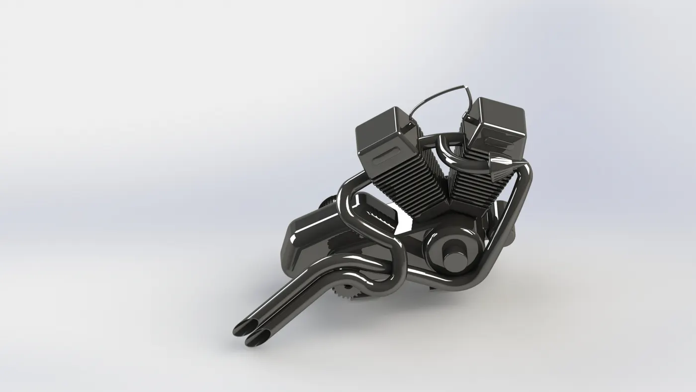
Engine:
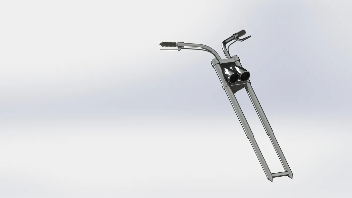
Front fork:
The front fork is the two long tubular things that hold the front wheel on the bike. That is but one function of the fork. They also move up and down to soak up bumps in the road surface like a car shock absorber does. The spring allows the fork leg to compress over a bump and then "spring back ". Some of the important tools for modeling the fork are convert entities, projected curve, revolve, extrude, offset, fillet, linear pattern, move copy bodies, combine, revolve cut, mirror, etc.
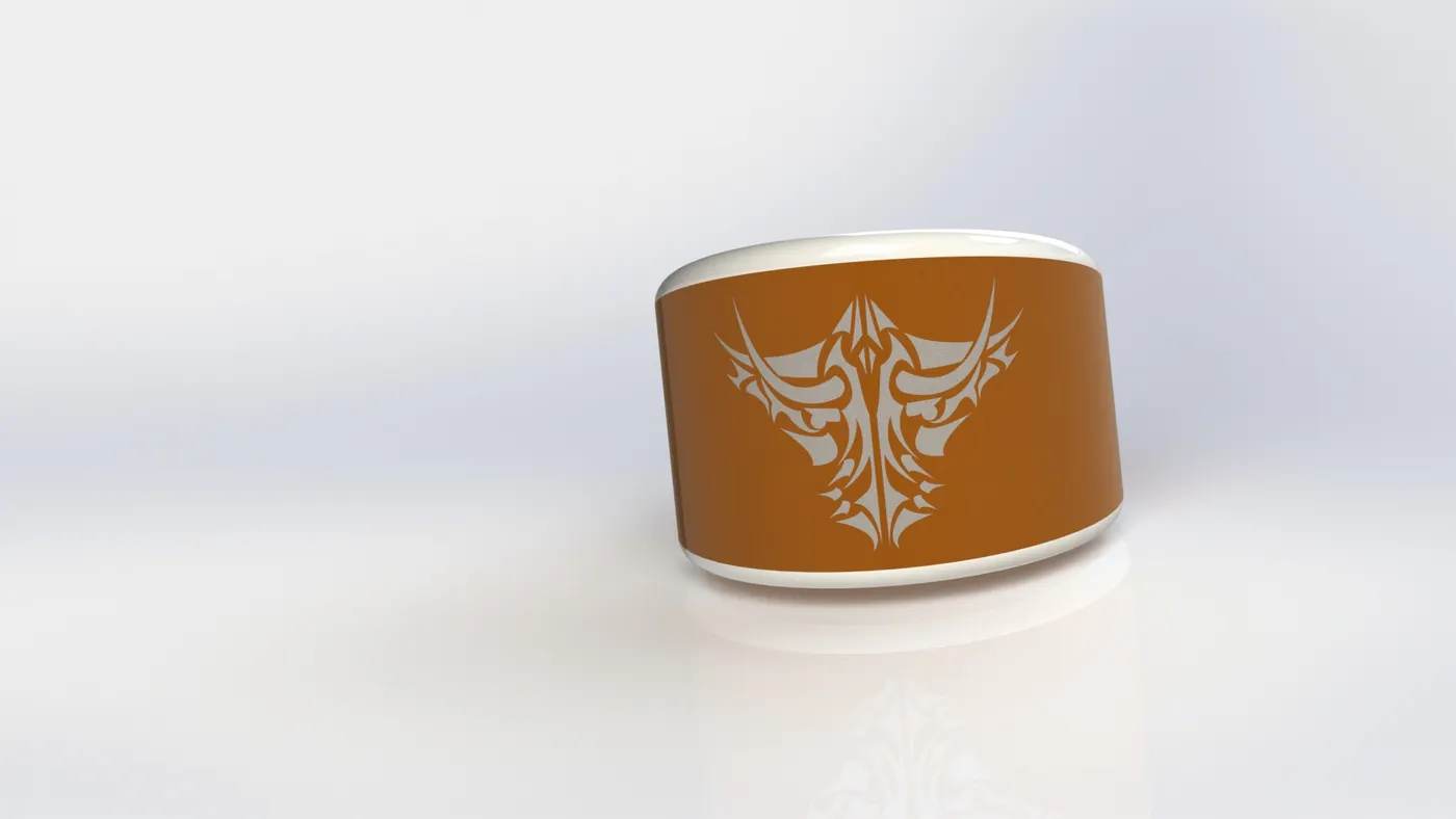
Oil tank:
The engine can be started up and manoeuvred on diesel oil or even a blend of diesel and heavy fuel oil. The mixing tank is used to collect recirculated oil and also acts as a buffer or reserve tank as it will supply fuel when the daily service tank is empty. Some of the important tools for modeloing the chopper are boss extrude, combine, fillet, shell etc.,
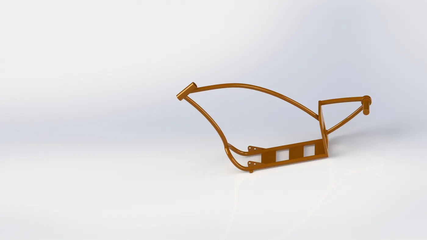
Chassis:
The chassis is the backbone of the motorcycle, to which all components are installed and connected. The chassis provides support points for the engine and the gas tank, as well as a pivot point where the steering rod is installed. Another pivot point is placed for the scissors, which incorporates the suspension and the rear wheel with the chassis. This can be simple, double-cradle, multitubular, stamped sheet, double beam, monocoque, etc.
It is usually preferably made of steel or aluminum, in more rare cases in magnesium, carbon or titanium. The rigidity and geometry of the chassis are vital for its stability. Normally the necessary stiffness depends on the engine power and dynamic characteristics. Today all motorcycles are equipped with suspensions, in order to keep the wheels in contact with the ground for as long as possible through irregularities, ensuring stability and increasing ride comfort.
Some of the important tools to model the chassis are sweep, mirror, boss extrude, cut extrude, dome, combine, cut extrude, split tec.,
Gas tank:
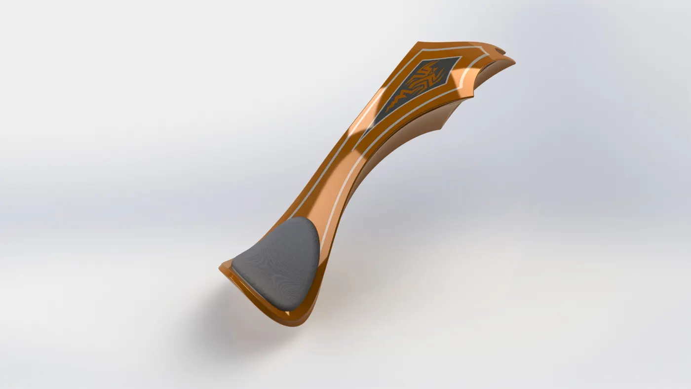
A fuel tank (or petrol tank) is a safe container for flammable fluids. Though any storage tank for fuel may be so called, the term is typically applied to part of an engine system in which the fuel is stored and propelled or released (pressurized gas) into an engine.
The features used for modelling gas tank are by using blue prints we had created a projected curve, and we had created a sweep surface. And used the trim surface to remove external surface. And we had used the surface loft for producing the surface of gas tank. We had used boundary surface for creating the remaining surface of gas tank. Then we used mirror option to mirror the surface. We have used extrude feature to create the seat and again we used boundary surface option to close the surface of gas tank. Some of the important tools used to build the gas tank is surface sweep, surface trim, surface loft, boundary surface, surface loft, surface knit, cut sweep, shell, etc.,
Assembly:
Assembling is the process of combaning the different parts with a sequence of joining through advanced mates like coincident, distance, angle, concentric, parallel, width, limit angle, etc.,
The motorcycle is the favorite means of transport for many people. This status has been achieved thanks to a series of advantages that make it unique since it allows you to save money and time in your travels (especially if we talk about the city). In addition, the motorcycle is the motorized vehicle with less gasoline, maintenance is much cheaper than that of a car, in addition to the feeling of freedom and agility that it conveys in its driving.
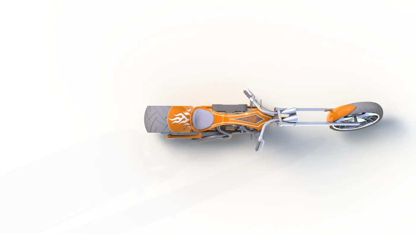
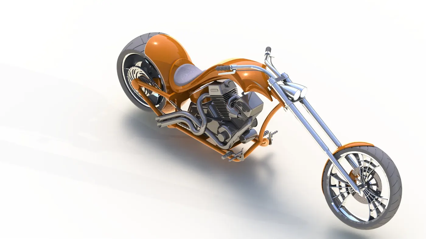
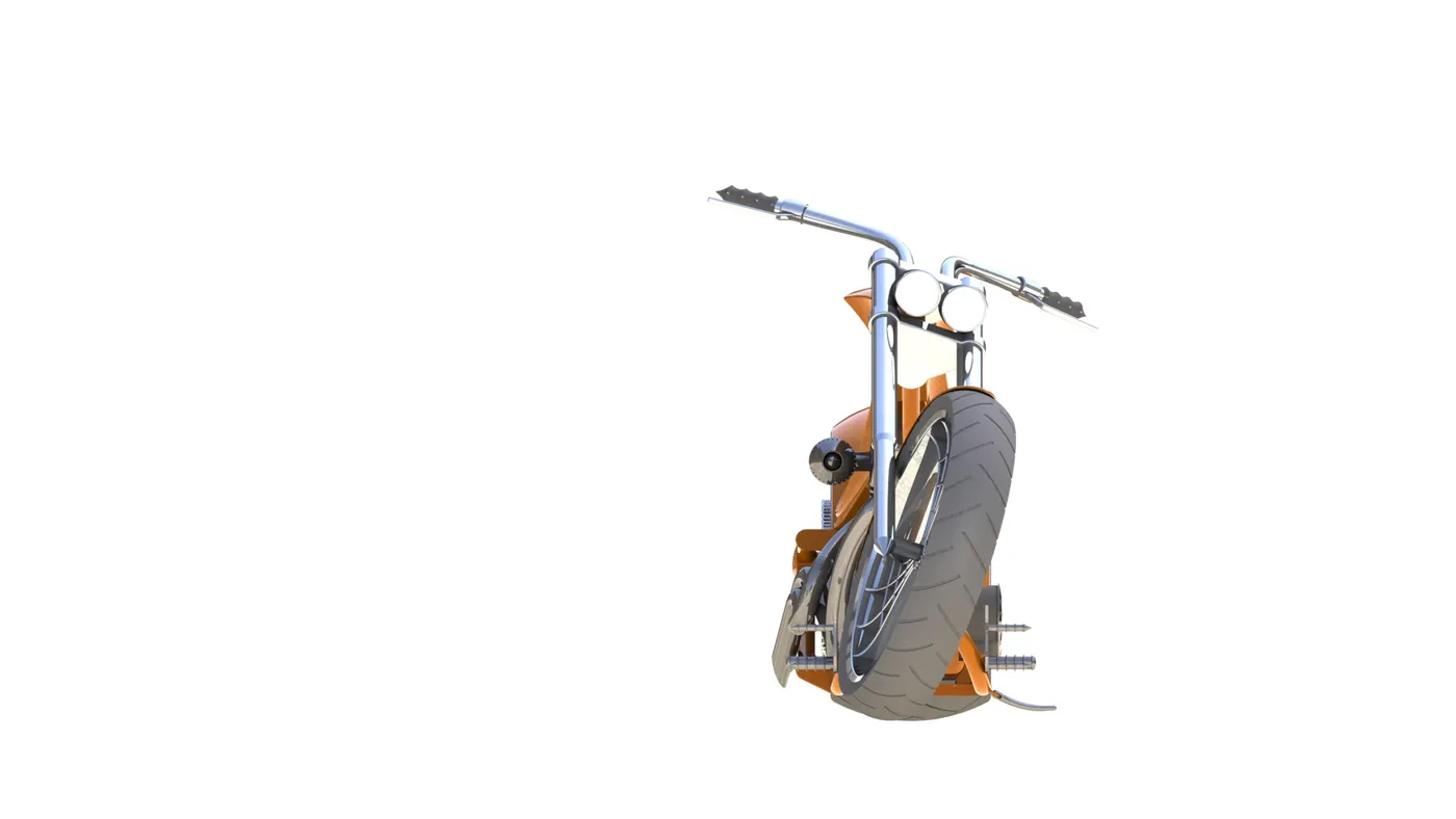
Camera view
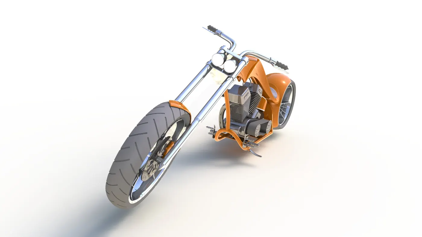
Front view
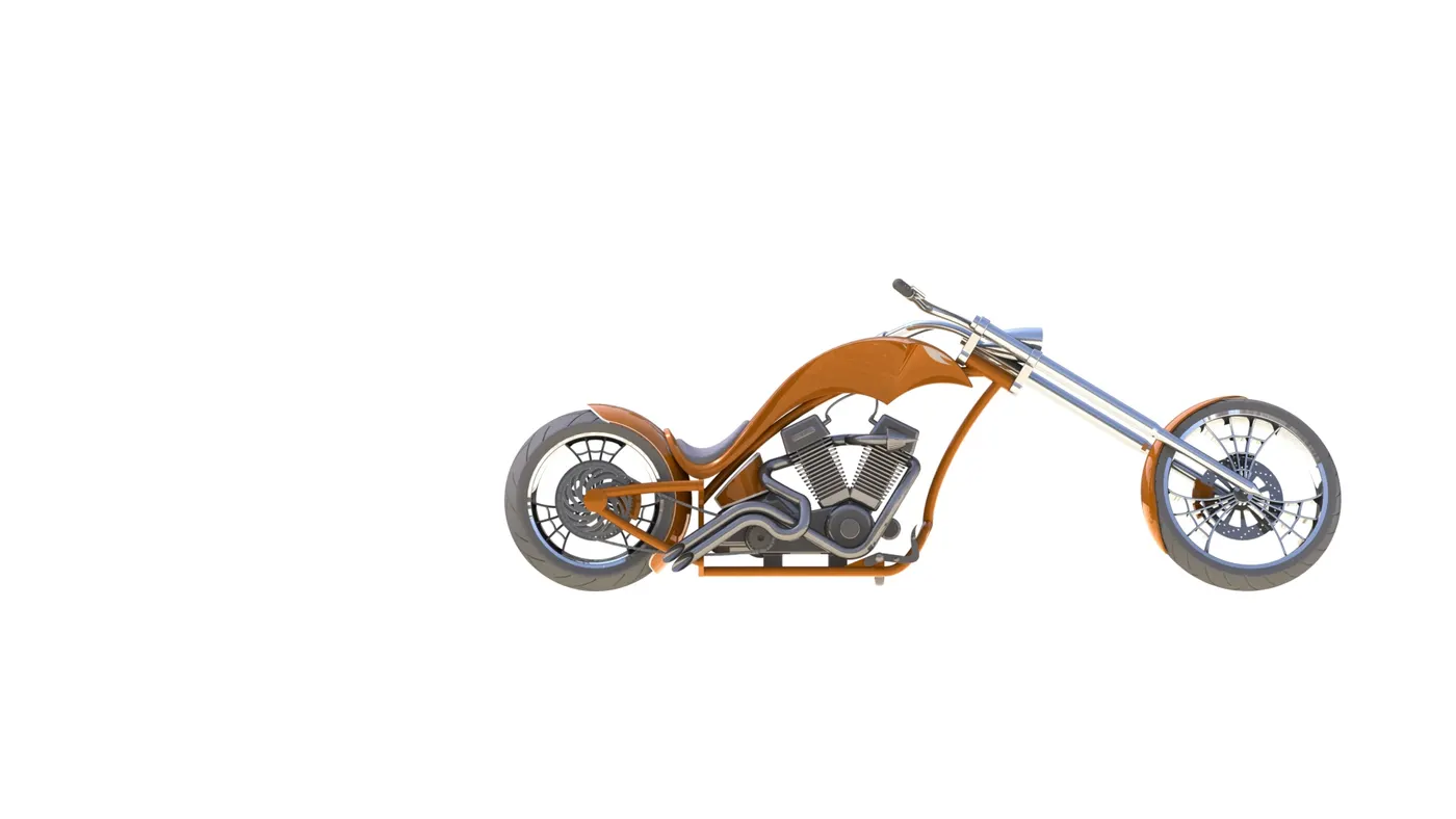
Top view
Isometric view
Right side view
Left side view
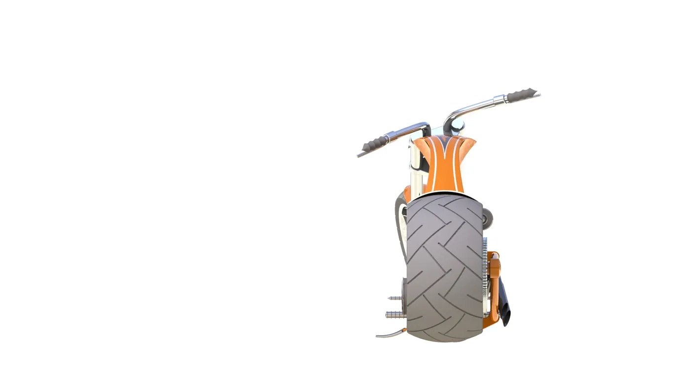
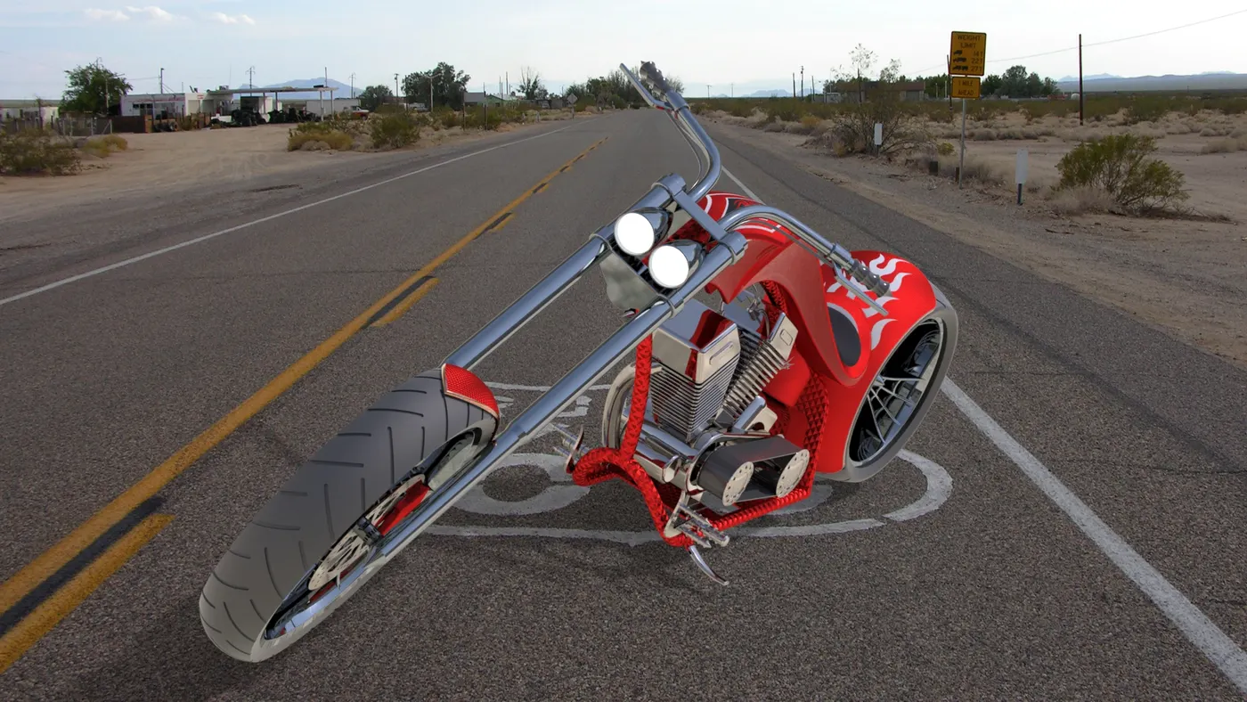
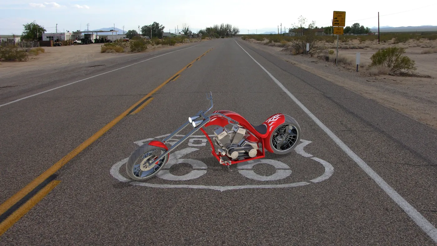
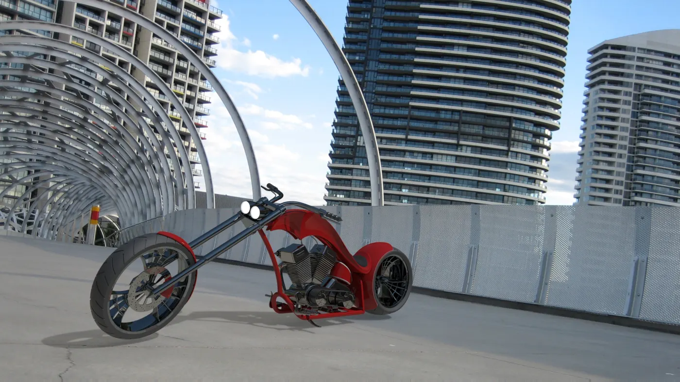
Photo realastic rendering of American Chopper:
Photorealistic rendering is highly driven by the real lights that create the actual shapes and textures when the 3D design is photographed.Rendering or image synthesis is the process of generating a photorealistic or non-photorealistic image from a 2D or 3D model by means of a computer program. The resulting image is referred to as the render. Multiple models can be defined in a scene file containing objects in a strictly defined language or data structure. The scene file contains geometry, viewpoint, texture, lighting, and shading information describing the virtual scene.
Conclusion:
By this project i am able to learn how to design the component in the solidworks, how to assemble the different parts by using the advanced mates, how to modeled the component and how to create the photo realistic rendering for chopper. Finally the required views and documentation is provided.