Photo Realistic Rendering
Title of the Project -
Assembly and Rendering of Chopper Model
Objective -
To design, assemble, and render a 3D model of a chopper using CAD software, showcasing various parts, their
assembly, and rendered images from different views.
Introduction -
The chopper model assembly involves designing individual components and combining them into a complete
assembly. This project aims to apply advanced CAD modeling techniques, demonstrate rendering capabilities, and
provide a detailed report explaining the design process, tools used, and final outputs.
Design Methodology/Approach -
The methodology for designing and assembling the chopper model is as follows:
1. Part Design: Create individual components like the frame, wheels, engine, handlebars, and seat using CAD
software.
2. Assembly: Use the assembly workspace to align and constrain the parts in their correct positions.
3. Rendering: Generate realistic images of the model by applying materials, lighting, and camera setups.
4. Documentation: Compile the results, including renders and detailed descriptions of the process, in a report.
Flowchart:
Start → Sketching and 3D Modeling of Parts → Assembly of Parts → Rendering → Documentation → End
Description Tools and Features Used
1. Sketching Tools: o Line, Circle, Rectangle, and Spline for initial 2D sketches.
2. 3D Modeling Tools: o Extrude, Revolve, Sweep, Loft, and Fillet for creating 3D parts.
3. Assembly Tools: o Mates (coincident, concentric, parallel) for proper alignment.
4. Rendering Tools: o Material application, lighting setup, and camera positioning for realistic renders.
Part Design
Frame: • Created using sweep for tubular sections and fillet for smooth joints.
Wheels: • Designed using revolve for tires and rims, and circular pattern for spokes.
Engine: • Modeled with extrude, chamfer, and patterning tools for fins and bolts.
Handlebars and Seat: • Developed using loft for ergonomic shapes and spline for aesthetic curves.
Assembly
The parts were imported into the assembly workspace and constrained using:
• Concentric mate for wheel and axle alignment.
• Coincident mate for frame and engine attachment.
• Parallel mate for handlebar and fork alignment.
Screenshots of the Assembly Model
1. Front View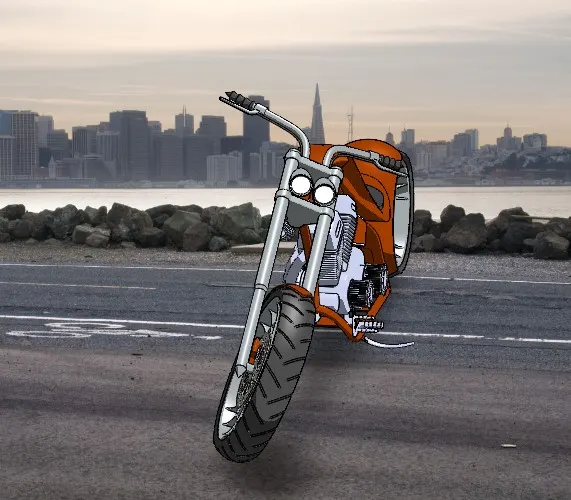
2. Side View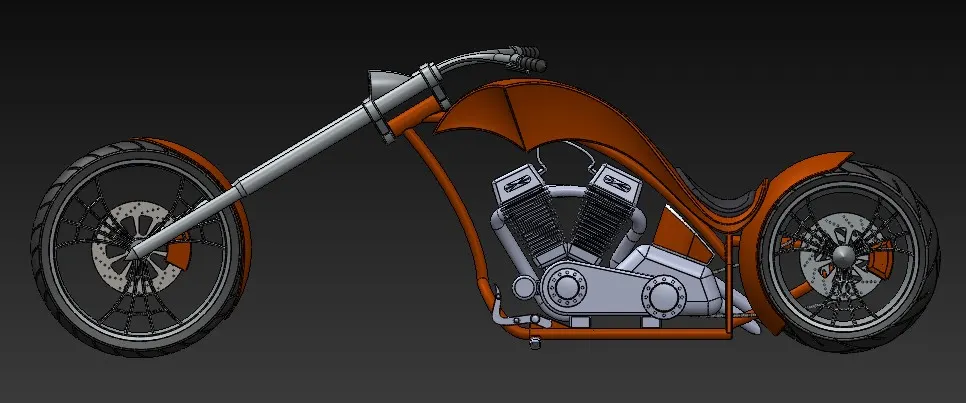
3. Isometric View -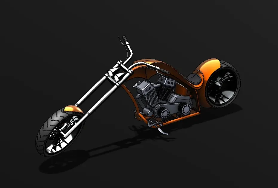
4. Top View -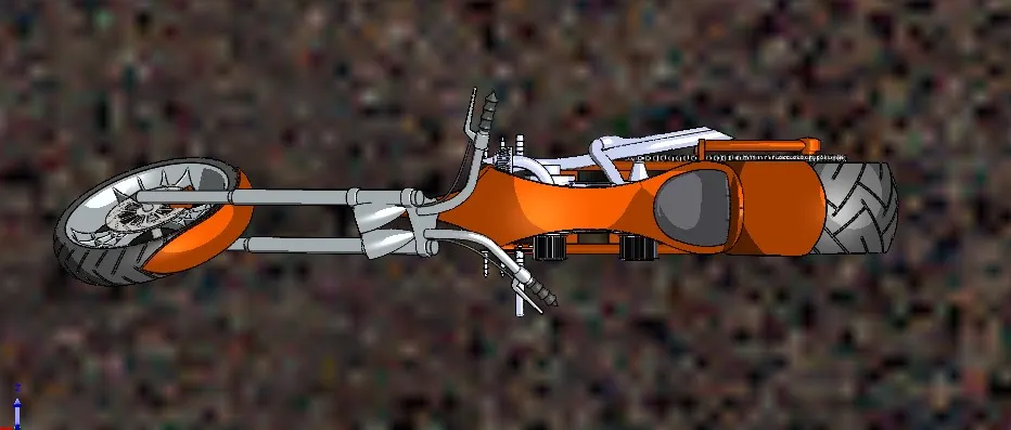
Back View - 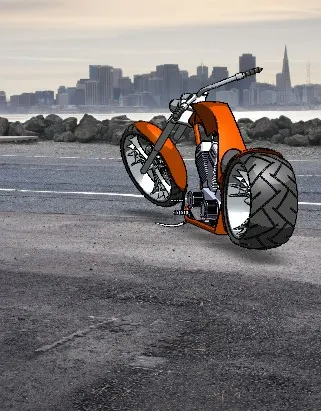
Rendered Images 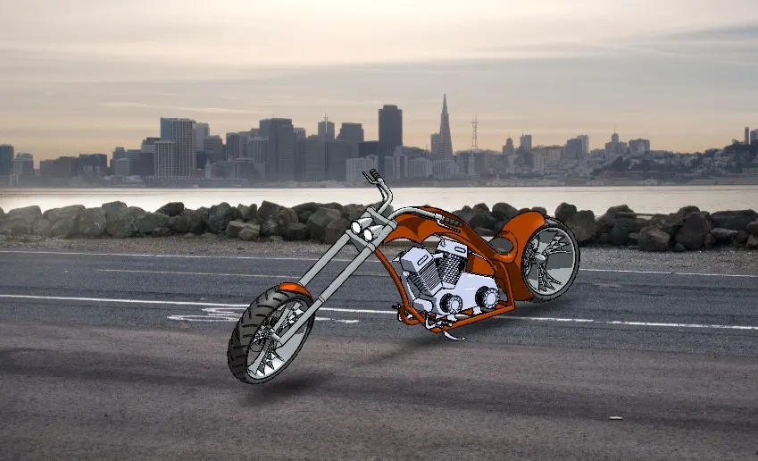
Conclusion - The assembly of the chopper model demonstrates proficiency in CAD modeling, assembly, and rendering techniques.
The project successfully highlights the use of advanced tools for part creation and realistic visualization. Future
improvements could include motion analysis or additional design optimizations for the chopper model
*****************************************************************************************************************************************************************************************************************