Photo Realistic Rendering
American Rendering
Report
AMERICAN CHOPPER
Objective:
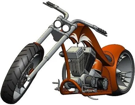
To model and assemble various parts of American Chopper using SOLIDWORKS. Later create Photo-realistic render of the American chopper.
Introduction:
SOLIDWORKS is a mechanical design application that lets designers Sketch out ideas, experiment with features, thus produce 3D models and make assembly of the modeled parts.
Integrated rendering tools helps the designer make photo realistic renders.
To accomplish the objective of the project and successfully model the American Chopper, following parts are to be modelled.
- Transmission Belt
- Kick Stand
- Front Fender
- Rear Fender
- Oil Tank
- Chain
- Pedal
- Front Wheel
- Rear Wheel
- Front Fork
- Chassis
- Engine
- Gas Tank
Final Assembly to be created making several mates and later positioning of the complete Assembly in space perfectly so as to get a realistic feel of the American Chopper grounded and supported on Side stand.
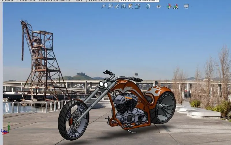
Appropriate Scene, Environment, Camera and Lighting to be added to get a realistic Final rendered Image.
Design methodology:
3D modeling
of parts
Applying materials and decals to individual parts
Assembly Final Render
Parts description:
Transmission Belt:
Features used to create Transmission Belt:
- Sketch
- Extrude Boss
- Fillet
Kick Stand
Features used to create Kick Stand:
- Sketch3
- Loft
- Dome
- Extrude Boss
- Extrude Cut
- Fillet
- Spline
Front Fender
Features used to create Front Fender:
- Sketch
- Revolve
- Dynamic Mirror
- Split
Rear Fender
Features used to create Read Fender:
- Sketch
- Revolve
- Shell
Oil Tank
Features used to create Oil Tank:
- Sketch
- Extrude Boss
- Combine
- Fillet
- Shell
Chain
Features used to create Chain:
- Sketch
- Fillet
- Extrude
- Patterns
Pedal
Features used to create Pedal:
- Sketch
- Extrude
- Fillet
- Linear pattern
- Dome
- Fillet
- Chamfer
Front Wheel
Features used to create Front Wheel:
- Sketch
- Revolve
- Trim
- Extrude Boss
- Revolve Cut
- Linear Pattern
- Circular Pattern
- Chamfer
Rear Wheel
Features used to create Rear Wheel:
- Sketch
- Revolve
- Trim
- Fillet
- Extrude Boss
- Revolve Cut
- Linear Pattern
- Fillet
Front Fork
Features used to create Front Fork:
- Sketch
- Extrude
- Trim
- Revolve
- Spline
- Move/Copy
- Dome
- Sweep
- Chamfer
- Fillet
Chassis
Features used to create Chassis:
- Sketch
- Projected Curve
- Trim
- Sweep
- Split
- Revolve
- Extrude cut
- Fillet
- Combine
Engine
Features used to create Engine:
- Sketch
- Trim
- Revolve
- Boss Extrude
- Cut Extrude
- Dome
- Projected curve
- Composite Curve
- Sweep
- Mirror
- Circular Pattern
- Fillet
- Split
Gas Tank
Features used to create Gas Tank:
- Sketch
- Extrude Boss
- Trim
- Surface Sweep
- Loft Surface
- Sweep Cut
- Shell
- Fillet
Assembly:
- American Chopper’s Assembly is done in the Assembly
- Multiple mates from Basic to Mechanical are applied so as to get each part fixed in its actual location.
- First part inserted in the Assembly environment is the Chassis, Mates of rest all of the parts is done w.r.t. Chassis. Reason being, in case there is requirement to move the American Chopper to place in a certain background, the assembly with all parts should be able to move. If mates are not done in this fashion, it is bound to receive error while trying to move the assembly and only the parts which have mate with Chassis will move with it and rest will be at the place of their mate. Hence, giving us a undesired
- Once assembled, the American Chopper should look like the below
Render:
- Rendering is a process of converting 3D models into realistic image
- Render of the American Chopper is done using Photo View 360 Add
- Appropriate Scene and Environment is selected from existing library
- Additional lights are included as per
- Camera is added at the angles and distance which will exhibit best shape of the Chopper. The camera view can be saved under the preferred name so that we can come back to the view in just 1 click and do not have to adjust multiple times to get the desired
- Integrated preview will allow us to see the render output of our selected Scene, Environment and lightings in the Solid works window, upon checking with multiple environments and light setting we can choose the one which will display the American Chopper as realistic as
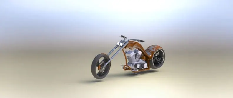
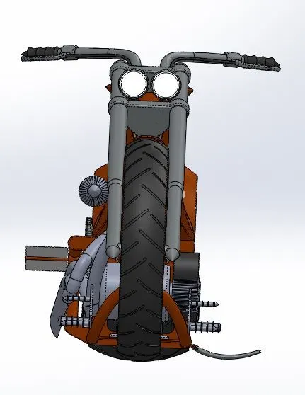
- Following are the images of my Final Render of the American
Conclusion and Course Outcome:
- All the parts of the American Chopper are successfully Modeled and
- A photo Realistic Render has been
- Understood Basics of 3D modeling and
- Understood Surface modeling, importance of projected curve and best ways to produce it as desired.
- Learnt about different environment, scenes and lighting settings to get the best possible, realistic looking render
Report By,
Vishwanathswami Hiremath