Photo Realistic Rendering
MODELING A AMERICAN CHOPPER ON SOLIDWORKS:
INTRODUCTION:
In this project, we have done modeling of American chopper using the SOLIDWORKS software. Firstly, we have learned how to use tools and commands. By using those commands and tools we started sketching by taking the American chopper as a reference. By taking the blueprint of American Chopper as a reference we modeled the parts of the chopper like:
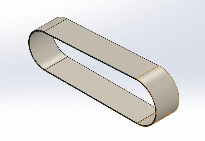
- Transmission Belt
- Chain
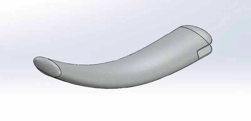
- kickstand
- Foot pedal
- Front fork
- Rear fork
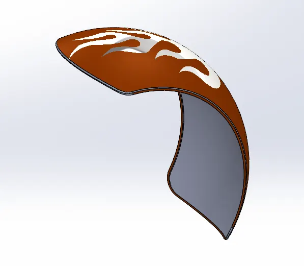
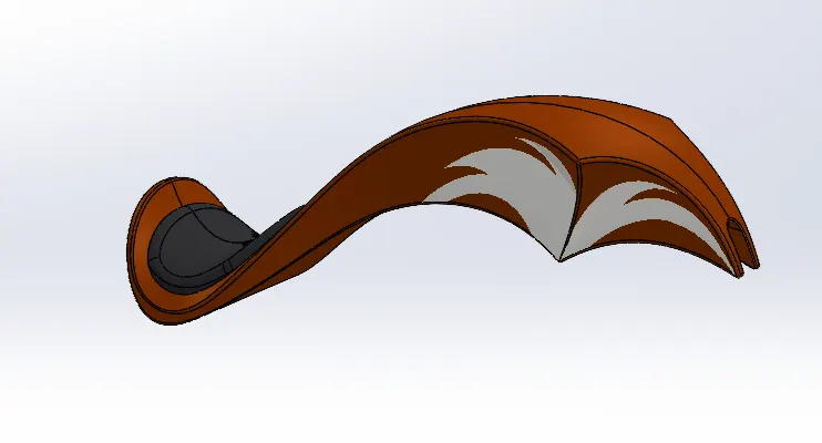
- Rear fender
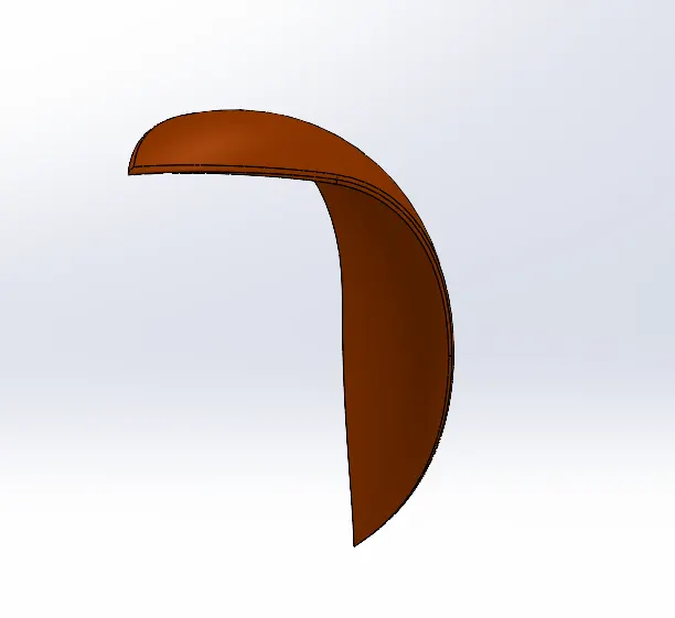
- Front Fender
- Engine(Including Exhaust system)
- Chassis
- Oil and Gas tank
- Front and Rear wheel
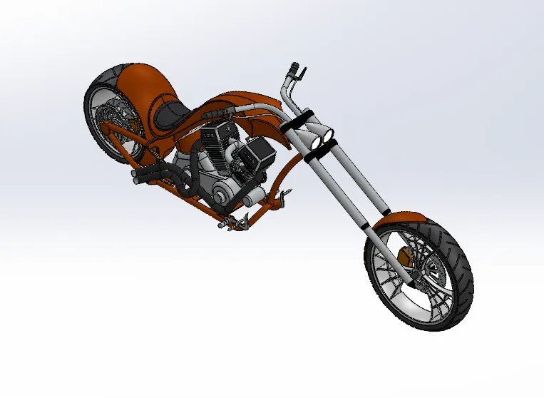
Then we started Assembly of the parts of the chopper to get output then we added decals, lights, camera, and rendering of the chopper by using SOLIDWORKS visualization.
OBJECTIVE:
The main objective of modeling of American Chopper on Solidworks is:
- To learn how to use Solidworks software.
- To learn the basic commands in Solidworks
- To learn the Modeling of choppers and to make products in a realistic manner.
- To learn the assembly of designed parts.
- To learn to model the parts taking reference of any blueprints.
- To make the setting of image quality using Photoview 360 option.
Design methodology/approach:
- Firstly, we designed the parts of the American chopper by taking the blueprint as a reference.
- Then we assembled all the parts that we modeled by using the assembly feature.
- Then we added colors for a good appearance and used decals to make my chopper decorative.
- Then we rendered the chopper using the Photoview 360 feature to make it realistic.
Description:
The description of each tool that used to make my chopper:
- Mirror:
This feature creates a copy of a solid product. It is a very helpful feature which makes our work very simple and saves our time.
- Mate:
This feature is used in the assembly template. This is used to make a bond between the parts of the product. it is very simple to use.
- Shell:
It is the best feature that helps us to find out whether any of the parts are clashing or merging. This tool is used to set the thickness of the geometry and material removed from the body and it becomes hollow.
- Fillet:
It is used to make edges soft by giving radius. It is used to hide the corners and edges. By using this feature our parts get a nice appearance.
- Extrude Boss:
This feature is used to make 2D sketches into a 3D solid body. It is the most basic feature in Solidworks. Also, we can use direction if it is blind, from the vertex, midplane, etc.
- Extruded cut:
This feature is to make our parts hollow. It is used to get the desired shape to the sketch or solid part.
- Revolve Boss:
This is used to make round material by using the axis as a reference. If we select the axis the material adds up around the axis by revolving around the axis.
- Linear pattern:
This feature works as a mirror but for the mirror option, it only gives a single copy but for the linear pattern it gives a sketch multiple times. Also, this feature is spaced equally between the sketches.
- Dome:
It is a feature that creates a concave dome by selecting the faces. We can dome many faces at a time. The measurement of the dome is given in radius format.
- Planes:
In Solidworks, this plays a vital role. This includes the Front plane, Top plane, and Right plane. By using these planes we model our part.
- 2D-sketches:
In this, we can create any sketches in 2D. By using various tools we can sketch any geometry also can create many relations.
- Smart Dimension:
It is a very handy tool. we can calculate dimensions right there and also we can modify the dimensions. We can measure angles, horizontal or vertical lengths, and so on
- Trim entities:
It is a very helpful tool when we get any extra lines or entities that spoil our sketch we can remove them easily by using power trim. It is the tool that erases only extra lines that are not required. By using trim entities we can save our time.
- Views:
It is the feature which we can see our part or product easily in any view. We can edit our parts or sketches easily using views. It directly takes us to the view which is needed. It consists of Right, Left, Front, Top, Isometric, trimetric and dimetric views.
- Loft:
By using this feature we can build complex products, profiles, and curves. It is a very important feature used for surface modeling.
- Split line:
It is the feature that divides selected faces into multiple separate faces. This tool projects an entity to surfaces or planar or curved faces.
DESIGNED PARTS:
Transmission Belt:
Kickstand:
Front Fender:
Rear Fender:
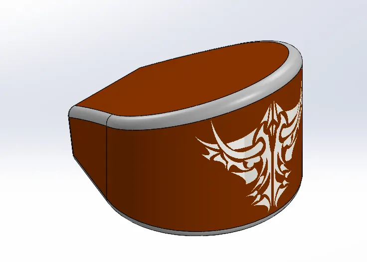
Oil Tank:
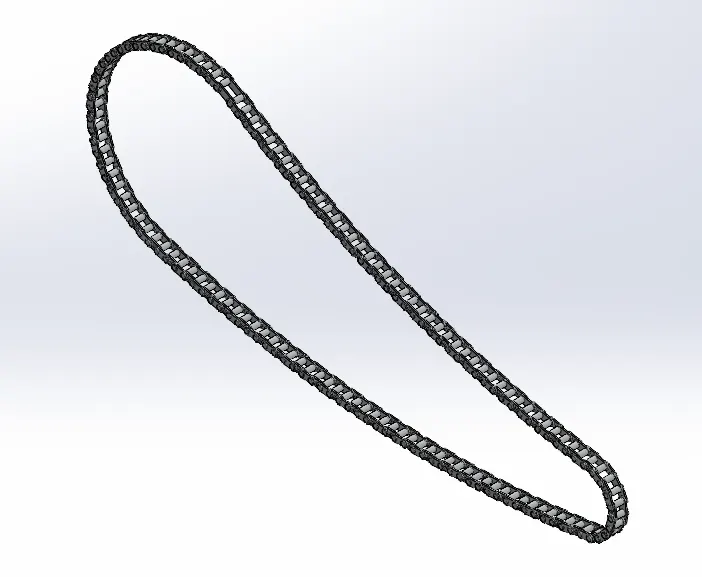
Chain Link:
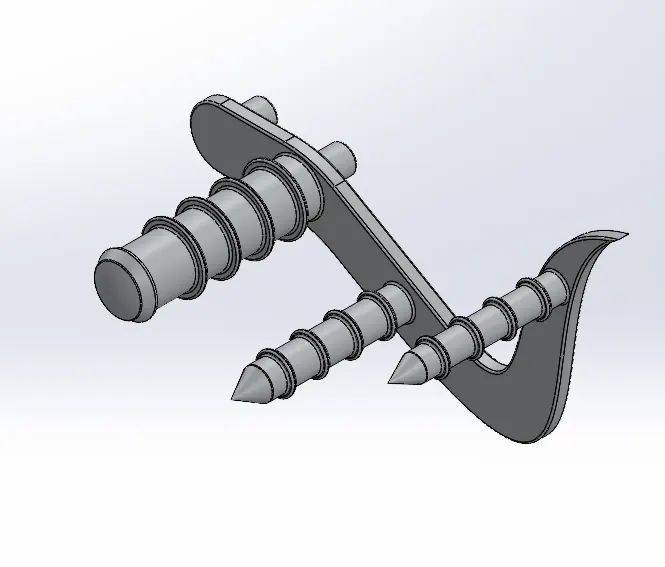
Pedal:
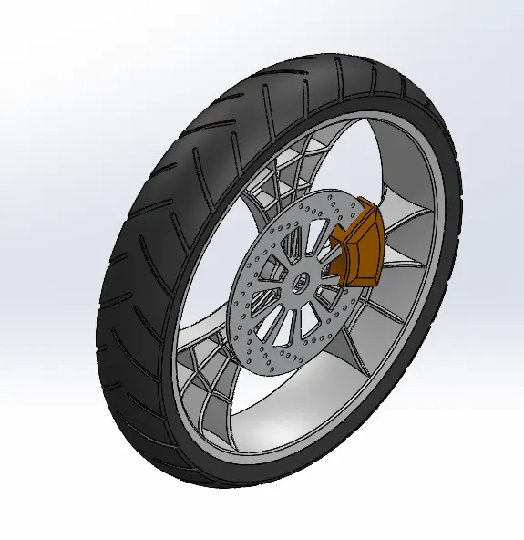
Front Wheel:
Rear Wheel:
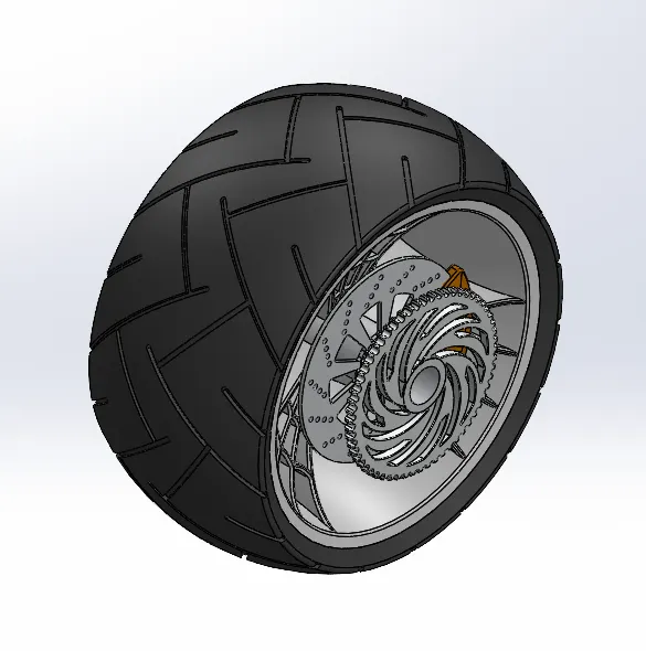
Front Fork:
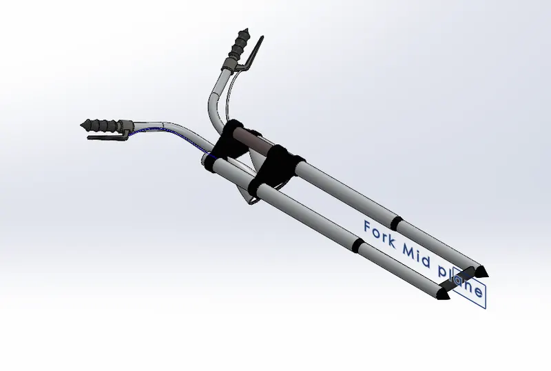
Chassis:
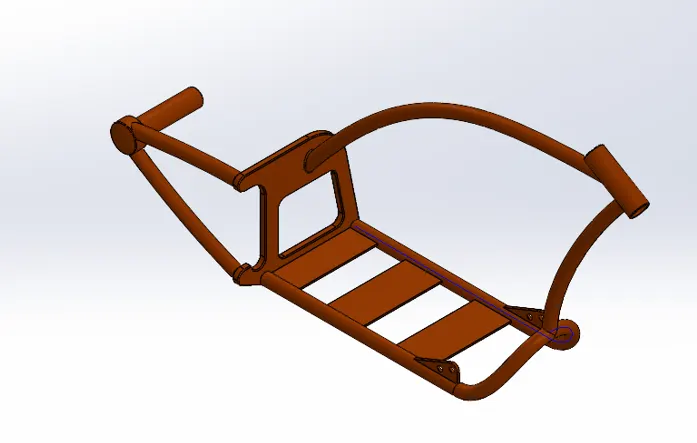
Engine:
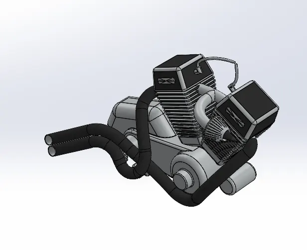
Gas Tank:
Assembly of the Chopper:
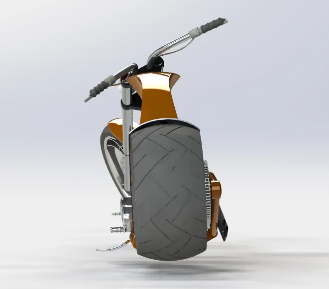
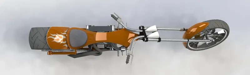
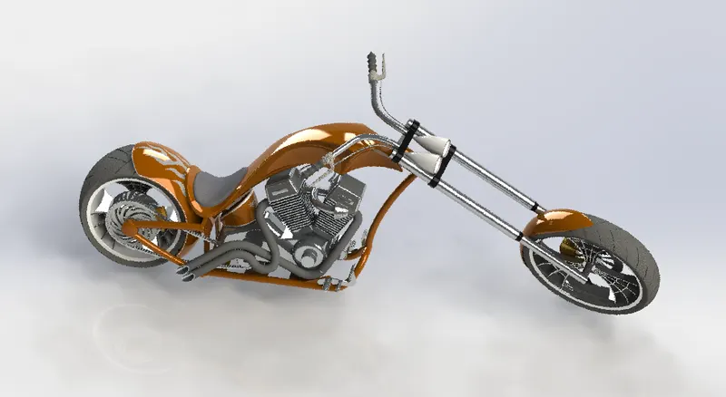
Rendering:
Front View:
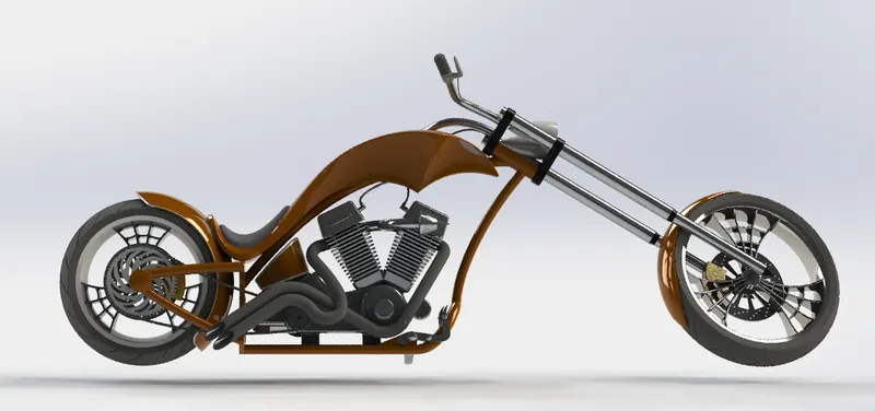
Right View:
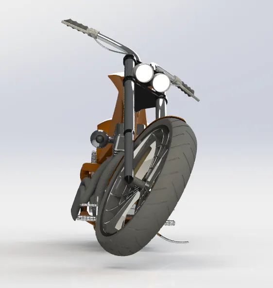
Left View:
Top View:
Isometric View:
Conclusion:
- Finally, I conclude by modeling this American chopper I have got experience with SOLIDWORKS software.
- Now I can model any new type of Chopper by taking the reference of any blueprint.
- The experience of Solidworks is so nice I have learned several things by building this American Chopper.