Photo Realistic Rendering
MODELLING AND RENDERING OF THE AMERICAN CHOPPER
OBJECTIVE:
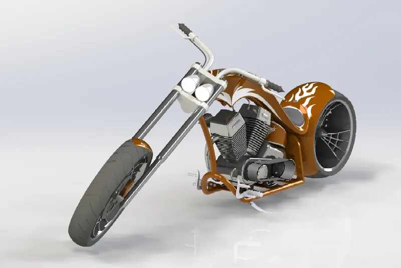
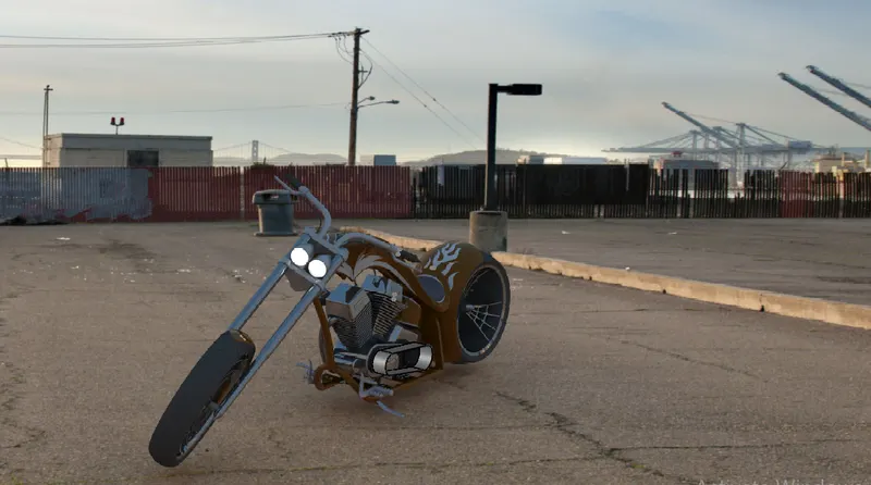
To create Modelling and Photo Realistic rendering of American chopper by using Solidworks.
EXECUTION:
STEPS FOR DESIGN:
- Open a new file.
- Selection of Plane
- sketch as per dimension
- Solid Modelling
- Fillet or chamfer
- Save the Model.
MODELLING:
THE CHOPPER CONSISTS OF THE FOLLOWING PARTS:
1. Chassis
2. Engine
3. Front Fork
4. Pedal
5. Chain
6. Oil Tank
7. Gas Tank
8. Transmission Belt
9. Front fender
10. Rear fender
11. Front Wheel
12. Rear Wheel
13. Kick Stand
All parts are designed seperately and finally assembled together to get the American Chopper.
Week 1:
PARTS:
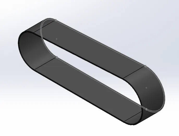
1. Transmission Belt
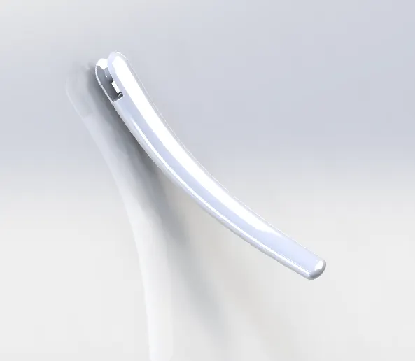
2. Kick Stand
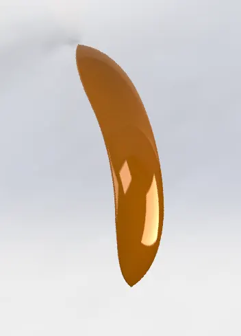
3. Front Fender
Command's used:
- 2d sketch
- lines and circles
- Extrude
- revolve
- Dome
- Fillet
Week 2:
PARTS:
4. Oil tank
5. Chain
6. Pedal
Command's used:
- 2d Sketch
- Sweep
- Revolve
- Splines
- Trim
- Extrude cut
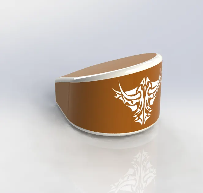
In oil tank we are creating two solid bodies then we are combine that two bodies in to a single body by combine feature. Than we have add fillet at corners.
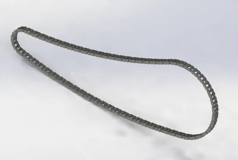
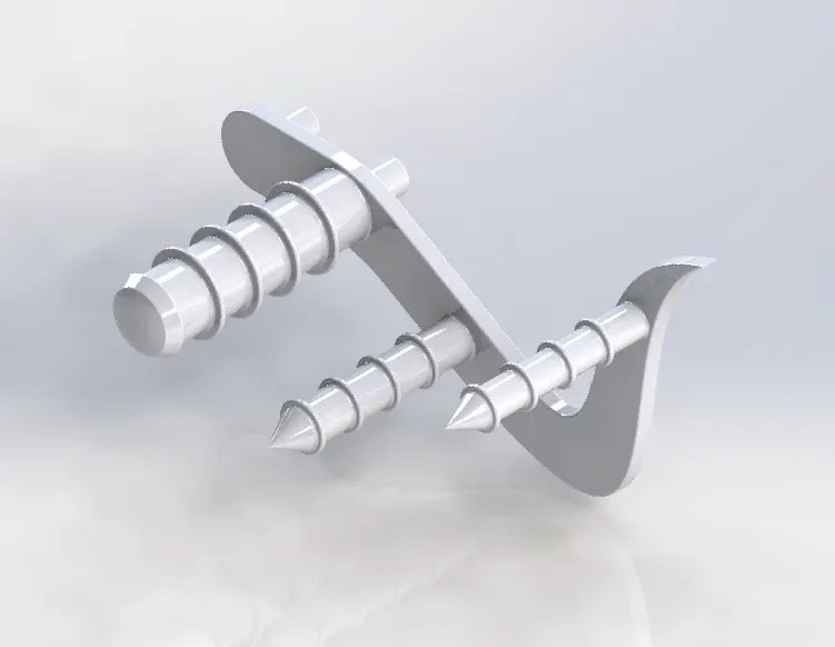
To make the new block inside the drawing while creating the chain is more useful for easy mirror.
Week 3:
PARTS:
7. Front wheel
Command's used:
- 2d Sketch
- Sweep
- Revolve cut
- Circular pattern
- Combine
- Extrude cut
- Revolve cut
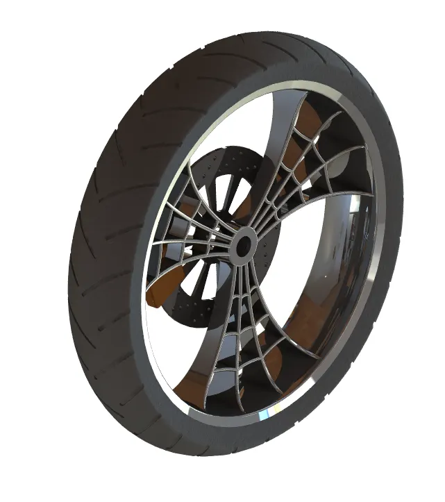
In Front wheel we are using Circular Pattern for making the spider web for the rim. Revolve Cut is also used for the rim to get the better surface finish.
Week 4:
PARTS:
8. Rear Wheel
9. Front Fork
Command's used:
- 3d sketch
- Sweep
- Revolve
- Mirror Pattern
- Dome
- Projected Curve
- Combine
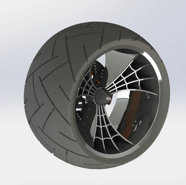
The Rear Wheel is same as the Front Wheel Chain Sprocket is the additional part we have to design in the Rear wheel.

The usage of the projected curve and sweep is given for the better finish in the handle of the Front fork.Mirror pattern is also used to make other side of the Front fork to complete.
Week 5:
PARTS:
- Chassis
- Engine
Command's used:
- Sweep
- Extrude
- Revolve
- Dome
- Project curves
- Split
- Mirror
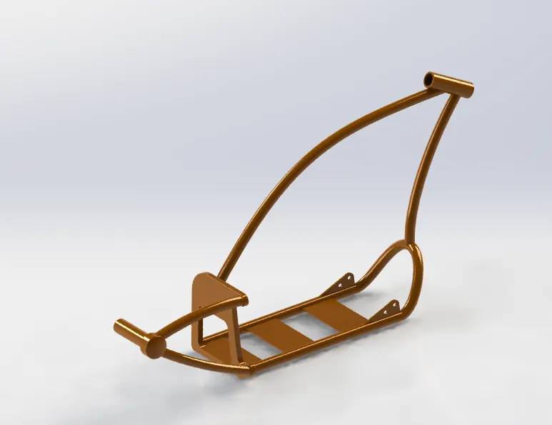
In Chassis model most of the surface modelling tool like sweep and project curves are used to give the better finish.
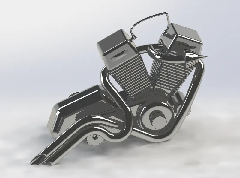
The project curves are used to make the engine Exhaust, most of the Solid modelling features are used to finish the engine.
Week 6:
- Gas Tank
Command's used
- Surface loft
- surface sweep
- Boundary surface
- Revolve
- Extrude
- Knit surface
- Projected Curves
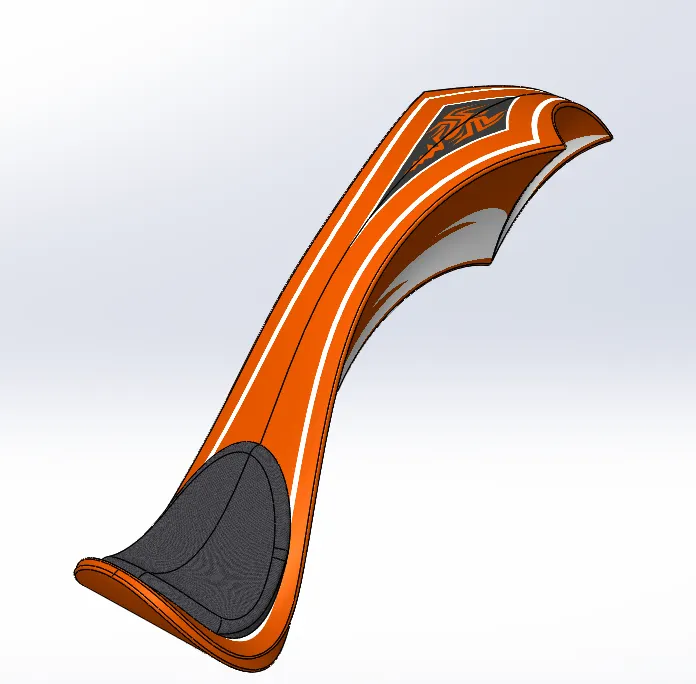
In gas tank both surface and soild modelling tools are used for the better finish.
After making all the parts, material for each part are given by the apperence option in solidworks. This is useful to give the more realistic outlook of the product.
ASSEMBLY OF THE AMERICAN CHOPPER:
To make the assembly of the American Chopper we have to use some of the mates. They are following below
- Concentric mate
- Parallel mate
- Angle mate
- Distance mate
- Advance mate
PHOTOVIEW 360 RENDERING:
To make the chopper more realistic to use the photoview 360. The usage of commands in photoview 360 like camera, Decals, Edit scenes and etc.
CONCLUSION:
Modelling, Assembly and Rendering of an American Chopper is sucessfully Done by soildworks.