Photo Realistic Rendering
Modelling American Chopper using SOLIDWORKS Software
1.Objective:
The objective of this product was to successfully model the American Chopper Bike and to learn how to use the SOLIDWORKS software fluently while doing so.
2.Introduction:
The objective of this report is to describe the process of modelling the American Chopper bike using the SOLIDWORKS software.
3.Approach of design:
The designing of the bike was done using the following steps:
- Step 1: The first step was to design all the parts of the bike as per the give instructions.
- Step 2: The second step was to assemble all the modeled parts.
- Step 3: The third step was to create camera set up light settings etc.
- Step 4: The fourth step was to do the rendering of the bike.
There were various features of the SOLIDWORKS software used while modeling the bike. The list of the features used is as follows:
- 2D-Sketches: This feature helps you create any geometry which is 2D and the created 2D geometry can be controlled by applying relations and these sketches can be modifies using various sketch tools.
- Boss Extrude: This feature allows us to take our 2D sketch and convert it into a 3D solid body by adding a third dimension of height/thickness to it.
- Revolved Boss: This feature allows us to create a 3d object about an axis to create a solid body.
- Sweep: This feature creates a base, boss, cut, or surface by moving a profile (section) along a path, according to these rules:
- The profile must be closed for a base or boss sweep feature; the profile may be open or closed for a surface sweep feature.
- The path may be open or closed.
- The path may be a set of sketched curves contained in one sketch, a curve, or a set of model edges.
- The path must intersect the plane of the profile.
- Neither the section, the path, nor the resulting solid can be self-intersecting.
- The guide curve must be coincident with the profile or with a point in the profile sketch.
- Extrude cut: This feature helps us remove unnecessary material from the part.
- Trim: This feature helps us remove the extra 2D geometry which is unnecessary.
- Offset: This feature helps us offset the selected sketch entities by a given distance.
- Convert entities: This helps us convert the edges or faces of a 3d model to a 2d sketch for our further use.
- Loft: This feature helps us create a transition between profiles.
10.Dome: This feature helps us create a dome like structure on the selected faces of the sketch,
- Fillet: This feature helps us create an external or internal rounded part on the component.
- Knit: This feature helps us combine two or more faces and surfaces into one.
- Combine: This feature helps us combine two or more solid bodies into one.
14.Shells: This feature helps us create a hollow part out of a solid body.
- Surface Trim: This helps us remove the unwanted material of the surface.
- Split: The Split Line tool projects an entity (sketch, solid, surface, face, plane, or surface spline) to surfaces, or curved or planar faces. It divides a selected face into multiple separate faces.
- Chamfer: This feature helps us creates a beveled feature on selected edges, faces, or a vertex.
The bike consisted of 13 parts which are:
- Transmission belt:
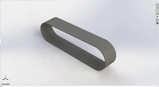
The features used to model this part were:
- 2D sketch
- Boss extrude
- Fillet
- Kick Stand:
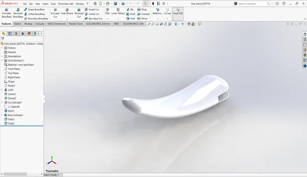
The feature used to model this part were:
- 2d sketch
- Loft
- Dome
- Split
- Boss extrude
- Fillet
- Front Fender:
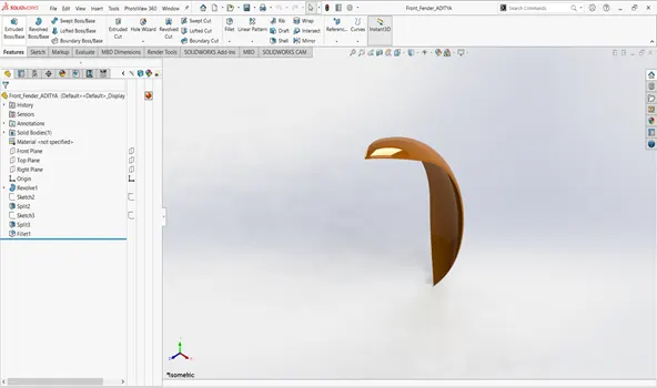
The features used in this part are:
- 2d sketch
- Revolve
- Split
- Fillet
- Rear Fender:
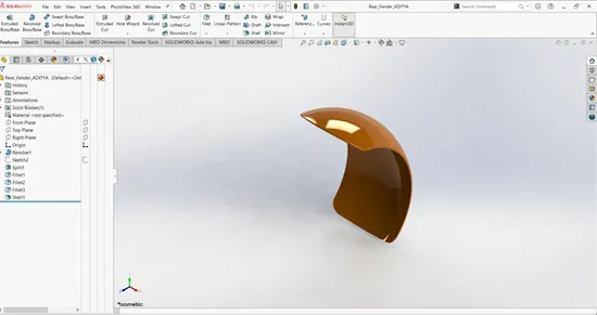
The features used to model this part are:
- 2D sketch
- Revolve
- Split
- Fillet
- Shell
- Chain:
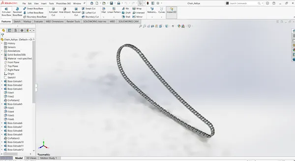
The part was modeled using the following features:
- 2d sketch
- Boss extrude
- Fillet
- Curve pattern
- Mirror
- Oil Tank:
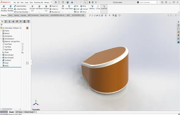
The features used to model this part were:
- 2D sketch
- Boss extrude
- Shell
- Combine
- Fillet
- Pedal:
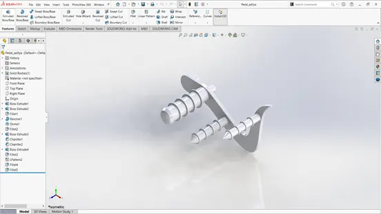
The features used to model this part are:
- 2D sketch
- Boss extrude
- Revolve
- Fillet
- 3D Linear pattern
- Chamfer
- Front Wheel:
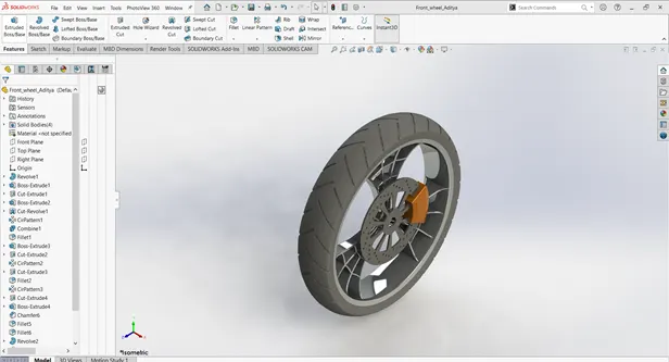
The features used to model these parts were:
- Revolve
- Boss extrude
- Cut extrude
- Cut revolve
- 3D Circular Pattern
- Fillet
- Chamfer
- Rear Wheel:
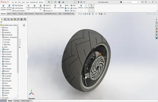
The features used to model this part were:
- Revolve
- Boss extrude
- Cut extrude
- Cut revolve
- 3D Circular Pattern
- Fillet
- Chamfer
- Front fork:
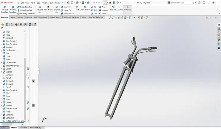
The features used to model this part were:
- 2D sketch
- Boss extrude
- Revolve
- Combine
- Projected curves
- Fillets
- Cut revolve
- Mirror
- Chassis:
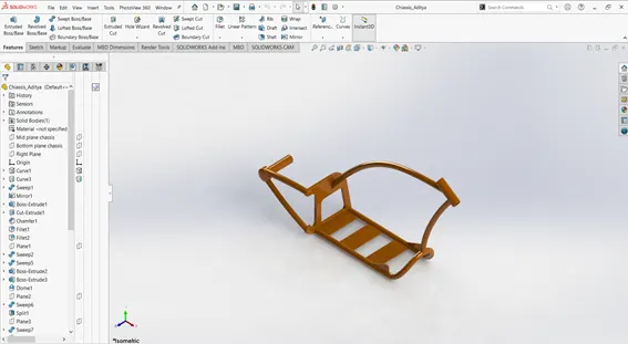
The features used to model these parts were:
- 2D Sketch
- Boss Extrude
- Projected curves
- Split
- Chamfer
- Sweep
- Dome
- Engine:
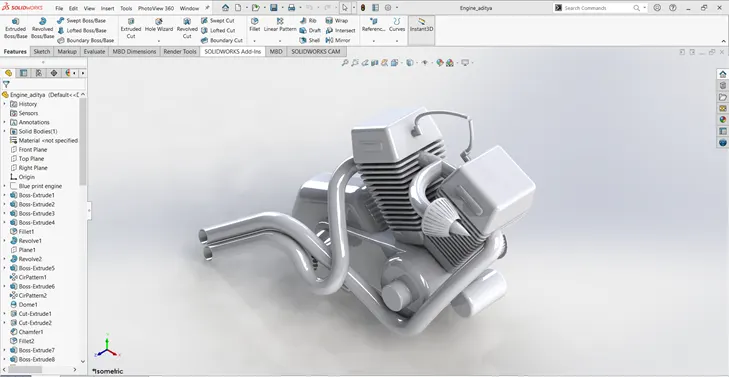
The features used to model these parts were:
- 2D sketch
- Boss extrude
- Fillet
- Chamfer
- 3d linear pattern
- 3d circular pattern
- Revolve
- Sweep
- Gas Tank:
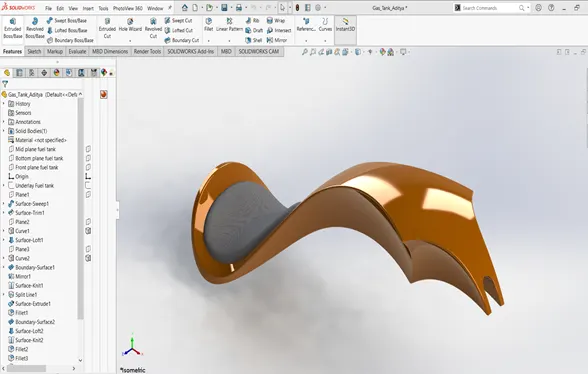
The features used to pattern this part were;
- Sweep
- Loft
- Boundary surface
- Cut sweep
- Fillet
- Shell
Assembly:
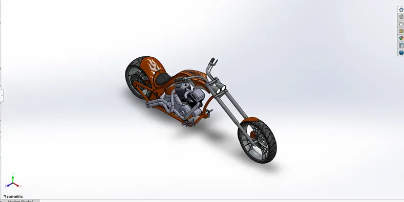
The last step was to take all these parts and assemble them in the assembly page of SOLIDWORKS where we applies different mates to the parts to assemble them and form a bike.
Rendering:
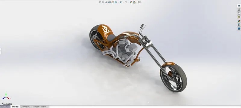
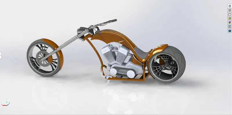
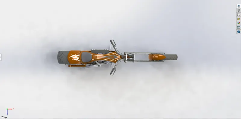
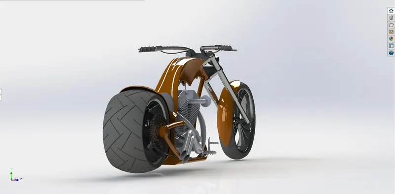
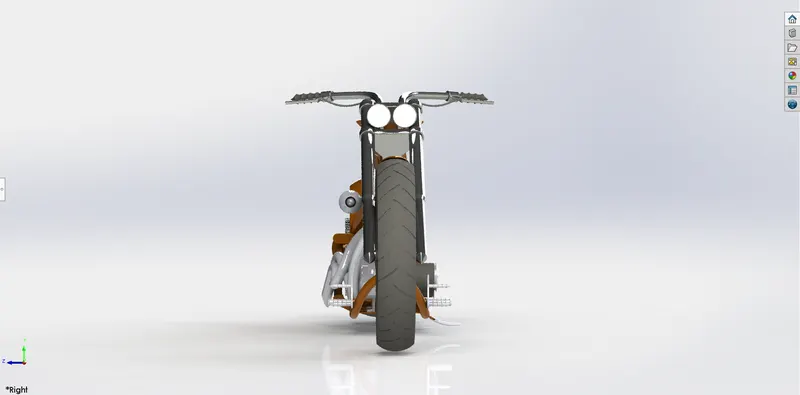
The rendering of the bike was done in photo view 360.
Conclusion:
The American Chopper bike was modeled and rendered sucessfully.
Respected sir do not have a visuals software so i could not render so i has been rendered in phot view 360.