Photo Realistic Rendering
AIM & OBJECTIVE
To create different parts of a American chopper in Solidworks using various types of sketches and features tools.
To assemble the different modelled parts to create the chopper.
To create photorealistic rendered images of the chopper using Solidworks Visualize.
INTRODUCTION
The chopper was modelled using part modelling. Once after all the parts were modelled separately they were assembled to create the chopper. It consists of following parts,
- Chain
- Chassis
- Engine
- Front fender
- Front fork
- Front wheel
- Fuel tank
- Kick-stand
- Oil tank
- Pedal
- Pedal LHS
- Rear fender
- Rear wheel
- Transmission belt
Design methodology

Description
Let’s see what are the tools and features used in the entire model to design different parts:
- Extrude boss
- Fillet
- Revolve boss feature
- Extrude cut
- Shell
- Linear pattern
- Mirror
- Reference geometry
- Projected curve
- Knit
- Mate
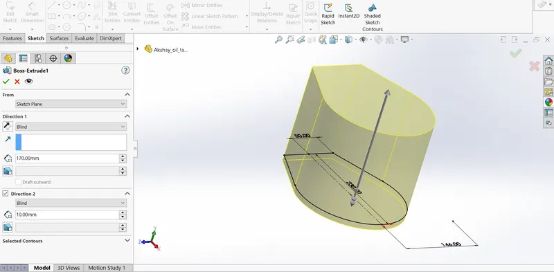
Extrude Boss :- The most basic feature from SOLIDWORKS is extrude boss. This feature needs a complete 2D sketch to convert 2D sketch into a solid body. When we exit the fully defined sketch we get boss extrude option and a property manager window pop-up. Into the property manager we see from where the feature begins and where it will end that we need to add dimensions to it. It creates a complete solid body of any shape with closed entities. In this feature we can add dimensions to both the direction.
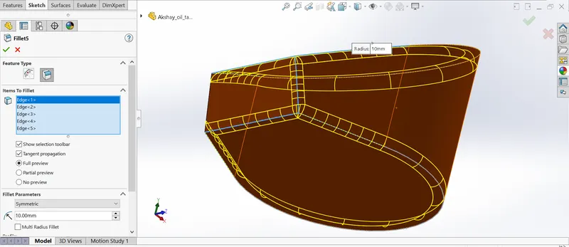
Fillet:- When we draw a solid part it is having some sharp edges. To give the roundness to those edges we add fillets. It makes the sharp edges or corners round shape of having different sizes or radius. The material can be added or removed according to conditions whether edges are internal or external. Fillets are used to solid bodies to hide the corners and edges and also it gives nice appearance to the part. Various types of fillets are used according to the given condition or it depends upon the part.
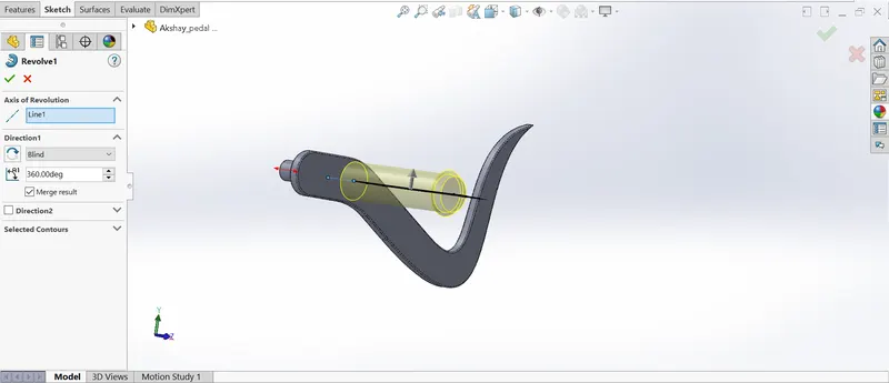
Revolve boss feature:- This feature works around an axis, by selecting axis of a sketch it adds a round material by revolving around that axis. If there is no axis we can select an edge of a sketch and it gives us appropriate geometry.
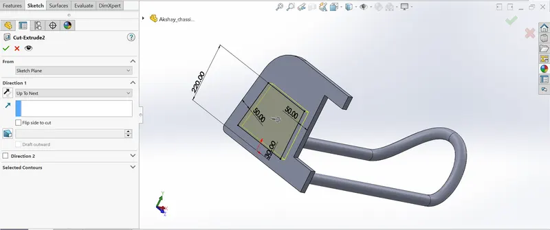
Extrude cut:- As the name implies, it cuts the geometry which we don’t need from the part or it can be used to give the desired shape to the sketch or solid part. When we draw sketch on the solid part and then we use extrude cut command it removes that part/surface.
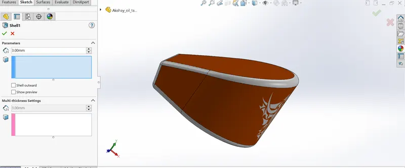
Shell:- It is very handy tool in SOLIDWORKS. It gives some sort of idea that how inside geometry of a part will appear. In this tool we give inside thickness to the geometry and material removed from the body and it becomes hollow.
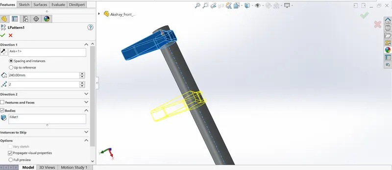
Linear pattern:- Linear pattern is used to create single sketch to use multiple times. The spacing, angles and path can be given in this feature to draw or create pattern. This feature spaced uniformly along one or two linear paths.
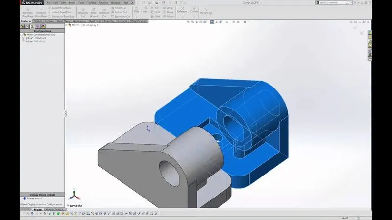
Mirror:- This feature creates copy of solid part. When this feature is applied it need plane or axis to mirror. Select the body which is to be mirror, select an axis or plane then apply feature and the mirrored part will get. Multibody parts: Apply feature to one or more multibody parts by selecting geometry pattern and using feature scope to choose which bodies should include the feature.
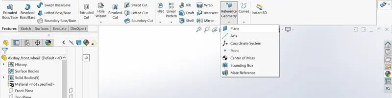
Reference geometry:- It defines the shape or form of a surface or a solid. This includes features such as planes, axes, co-ordinate system and points. This can be used according to need in a sketch.
Use of reference geometry example:
- Axis: If we want to pattern something and axis is not available by using reference geometry axis it gets easier to make pattern.
- Plane: If we need to sketch and there is need of plane by using reference geometry plane we can draw it and complete the sketch.
Projected curve:- The curve can be project by a sketch into a model to create a 3D curve. We can create multiple closed or open contour projected curves from a single sketch. Generally the curve can be intersection of two extruding surfaces. The curve which is created can be use as a path for the sketch of the part. Note: It do not create curve of an intersecting curves.
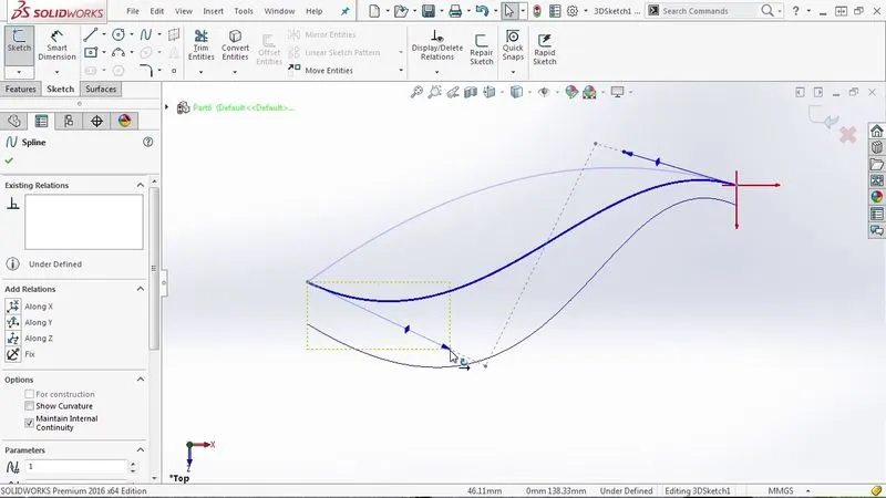
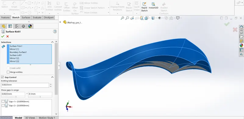
Knit:- Use of knit surface tool to combine two or more faces and surfaces into one. It create a solid body when the knit surfaces form a closed volume or leave as a surface body.
Mate:- Mate creates geometric relationship between assembly and component. When we add mates, it defines the allowable direction of linear or rotational motion of component within its degree of freedom, visualizing the assembly’s behavior.
This feature includes:-
- Coincident mate: Coincident mate make two planar faces to become coplanar. This mate can move along one another but cannot be separated.
- Concentric mate: This makes two circular faces to become concentric and can move along the common axis.
- Tangent: This feature can be use between a face and plane to make tangent mate.
- Angular mate: This make angular relation between flat surface and the surface having some angle.
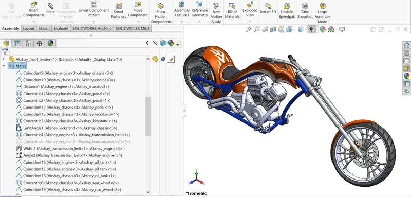
Now we have completed discussion of how the features work under solid works. Let us see the application of the features in the chopper that we have built. We are going to discuss part by part as shown in the flowchart.
Part Modelling: The 3D part is the basic building block of any large scale design. Features are the individual shapes that, when combined, make up the part. One can also add some types of features to assemblies. Part documents can contain multiple solid bodies that we can manipulate the same way as single solid bodies.
CHAIN
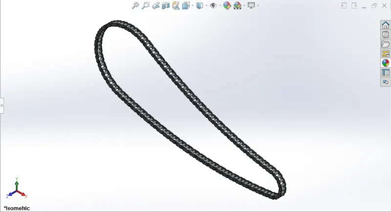
Motorcycle chains are part of the drive train to transmit the motor power to the back wheel. Properly lubricated chains can reach an efficiency of 98% or greater in the transmission. Unlubricated chains will significantly decrease performance and increase chain and sprocket wear.
Commands used: Following were the commands used to model the part,
- 2D sketch
- Fillet
- Smart Dimensions
- Appearance
- Extruded boss/base
Image of the modelled part:
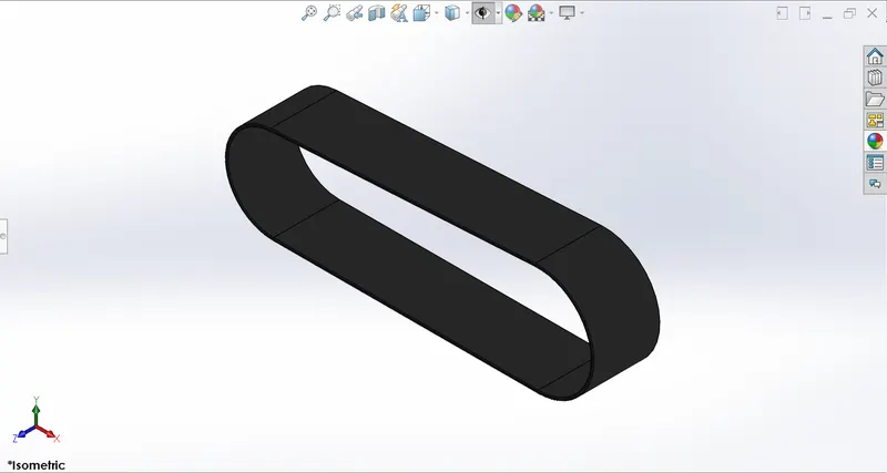
TRANSMISSION BELT
A belt is a loop of flexible material used to link two or more rotating shafts mechanically, most often parallel. Belts may be used as a source of motion, to transmit power efficiently or to track relative movement. Belts are looped over pulleys and may have a twist between the pulleys, and the shafts need not be parallel.
Commands used: Following were the commands used to model the part,
- 2D sketch
- Fillet
- Smart Dimensions
- Appearance
- Extruded boss/base
- Curve driven pattern
- Mirror feature
- Body-Delete/keep
Image of the modelled part:
FENDERS
A fender is the part of a vehicle that protects and frames its wheels and keeps mud from splashing it. Most modern vehicles have fenders on their front and back wheels.
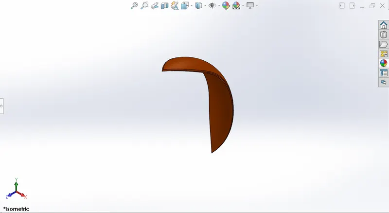
FRONT FENDER
It is for the front wheel.
Commands used: Following were the commands used to model the part,
- 2D sketch
- Fillet
- Smart Dimensions
- Appearance
- Split
- Revolve
Image of the modelled part:
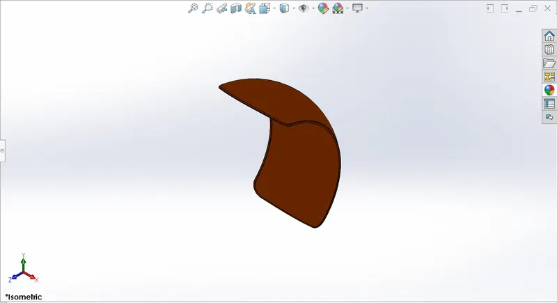
REAR FENDER
It is for the rear wheel. It also comprises of a decal.
Commands used: Following were the commands used to model the part,
- 2D sketch
- Fillet
- Smart Dimensions
- Appearance and decals
- Split
- Revolve
- Shell
Image of the modelled part:
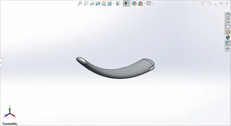
KICK-STAND
It is a metal rod attached to a bicycle or motorcycle, lying horizontally when not in use, that may be kicked into a vertical position to support the vehicle when it is stationary.
Commands used: Following were the commands used to model the part,
- 2D sketch
- Fillet
- Smart Dimensions
- Appearance
- Split
- Lofted boss/base
- Extruded boss/base
- EXtruded cut
- Dome
Image of the modelled part:
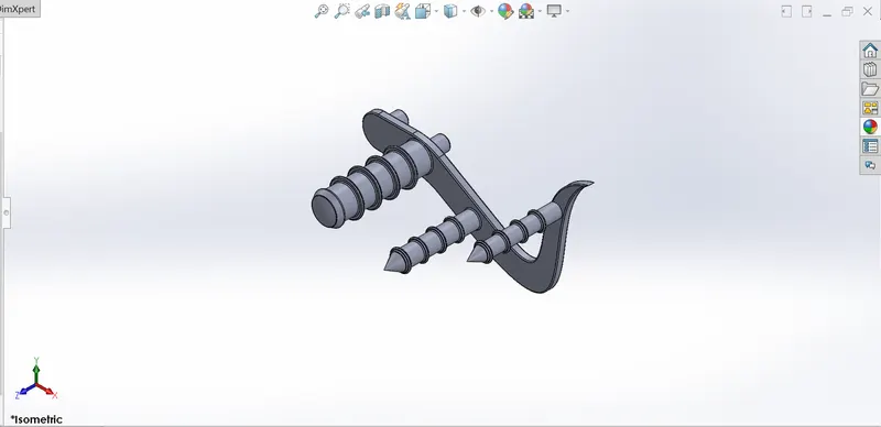
PEDAL
It is a foot lever or treadle by which a part is activated in a mechanism.
Commands used: Following were the commands used to model the part,
- 2D sketch
- Fillet
- Smart Dimensions
- Appearance
- Chamfer
- Revolved boss/base
- Extruded boss/base
- Linear Pattern
- Dome
Image of the modelled part:
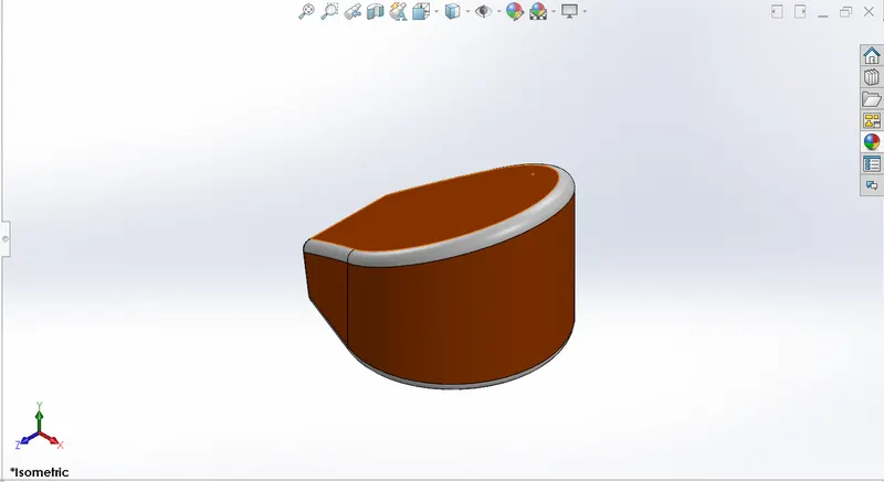
OIL TANK
It is a container for holding or storing oil. Oil tank also comprises of a decal.
Commands used: Following were the commands used to model the part,
- 2D sketch
- Fillet
- Smart Dimensions
- Appearance and decals
- Extruded boss/base
- Combine
- Shell
Image of the modelled part:
WHEELS
It is a circular object that revolves on an axle and is fixed below a vehicle or other object to enable it to move easily over the ground.
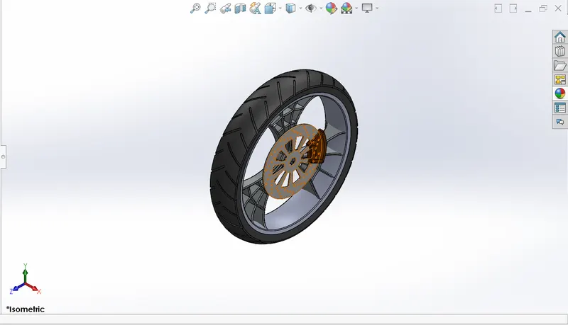
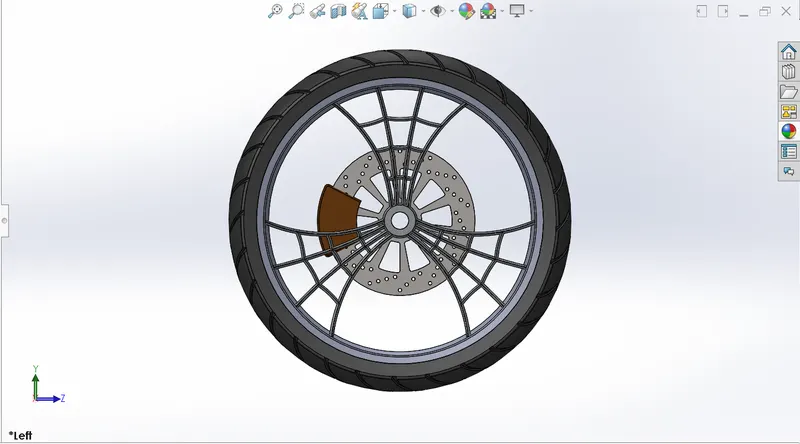
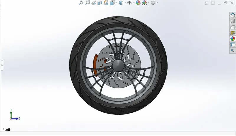
FRONT WHEEL
It is at the front of the vehicle. It consists of following components,
- Rim
- Disc brake (Rotor)
- Tyre
- Caliper
Commands used: Following were the commands used to model the parts,
- 2D sketch
- Offset entities
- Fillet
- Trim entities
- Smart Dimensions
- Appearance
- Chamfer
- Mirror Entities
- Extruded cut
- Revolved cut
- Combine
- Circular pattern
- Extruded boss/base
- Revolved boss/base.
Images of modelled part:
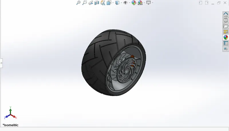
REAR WHEEL
It is at the back of the vehicle. It has following components in it,
- Rim
- Disc brake (Rotor)
- Tyre
- Sprocket
- Caliper
Commands used: Following were the commands used to model the part,
- 2D sketch
- Offset entities
- Fillet
- Trim entities
- Smart Dimensions
- Appearance
- Chamfer
- Mirror Entities
- Combine
- Extruded cut
- Revolved cut
- Circular pattern
- Extruded boss/base
- Revolved boss/base.
Images of modelled part:
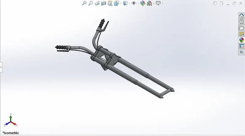
FRONT FORK
The front fork is a suspension component for either bicycle fork or motorcycle fork. The forks can be most easily understood as simply large hydraulic shock absorbers with internal coil springs. They allow the front wheel to react to imperfections in the road while isolating the rest of the motorcycle from that motion.
Commands used: Following were the commands used to model the part,
- 2D sketch
- Fillet
- Trim entities
- Smart Dimensions
- Appearance
- Dome
- Mirror Entities
- Body-Move/Copy
- Combine
- Extruded cut
- Revolved cut
- Circular pattern
- Linear pattern
- Projected curve
- Reference Plane
- Extruded boss/base
- Swept boss/base
- Revolved boss/base.
Image of modelled part:
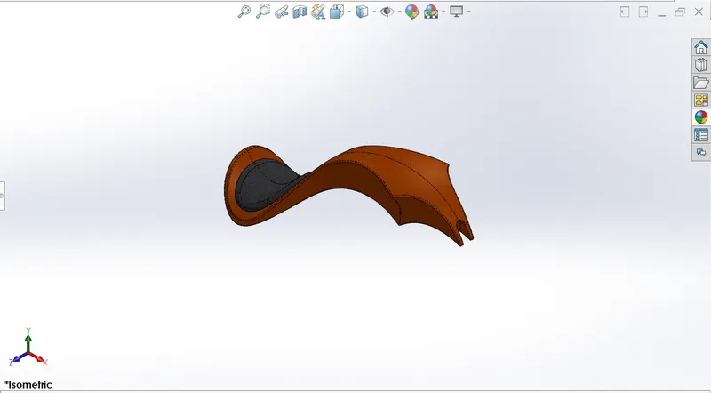
FUEL TANK
A fuel tank is a safe container for flammable fluids. Though any storage tank for fuel may be so called, the term is typically applied to part of an engine system in which the fuel is stored and propelled (fuel pump) or released (pressurized gas) into an engine. Fuel tanks range in size and complexity from the small plastic tank of a butane lighter to the multi-chambered cryogenic Space Shuttle external tank.
Commands used: Following were the commands used to model the part,
- 2D sketch
- Sketch picture
- Fillet
- Trim
- Smart Dimensions
- Shell
- Mirror
- Split line
- Projected curve
- Reference Plane
- Surface trim
- Swept cut
- Lofted surface
- Boundary surface
- Swept surface
- Extruded surface
- Knit surface.
Image of modelled part:
ENGINE
A motorcycle engine is an engine that powers a motorcycle. Motorcycle engines are typically two-stroke or four-stroke internal combustion engines, but other engine types, such as Wankels and electric motors, have been used.
Commands used: Following were the commands used to model the part,
- 2D sketch
- Sketch picture
- Fillet
- Smart Dimensions
- Trim
- Appearance
- Chamfer
- Mirror
- Split
- Combine
- Dome
- Extruded cut
- Circular pattern
- Linear pattern
- Projected curve
- Composite curve
- Reference Plane
- Extruded boss/base
- Revolved boss/base
- Swept boss/base.
Images of the modelled part:
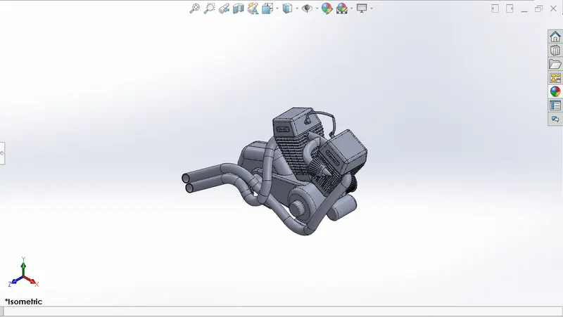
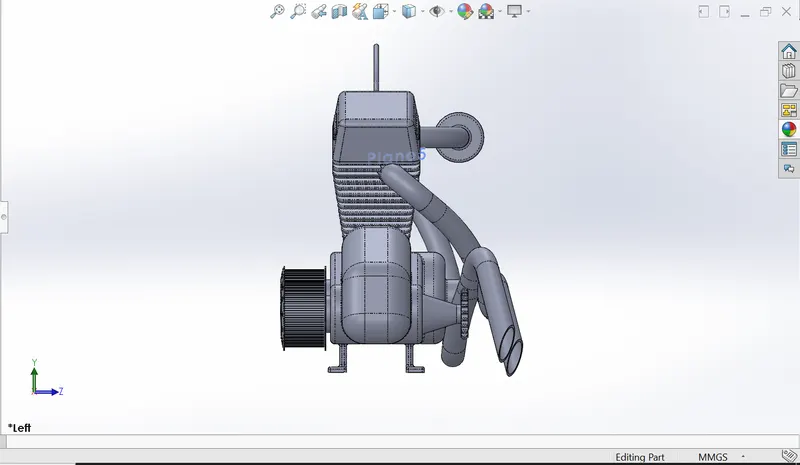
CHASSIS
It is a vehicle frame, the underpart of a motor vehicle, on which the body is mounted; if the running gear such as wheels and transmission, and sometimes even the driver's seat, are included, then the assembly is described as a rolling chassis.
Commands used: Following were the commands used to model the part,
- 2D sketch
- Sketch picture
- Fillet
- Split
- Smart Dimensions
- Appearance
- Chamfer
- Mirror
- Combine
- Dome
- Extruded cut
- Projected curve
- Reference Plane
- Extruded boss/base
- Revolved boss/base
- Swept boss/base.
Images of the modelled part:
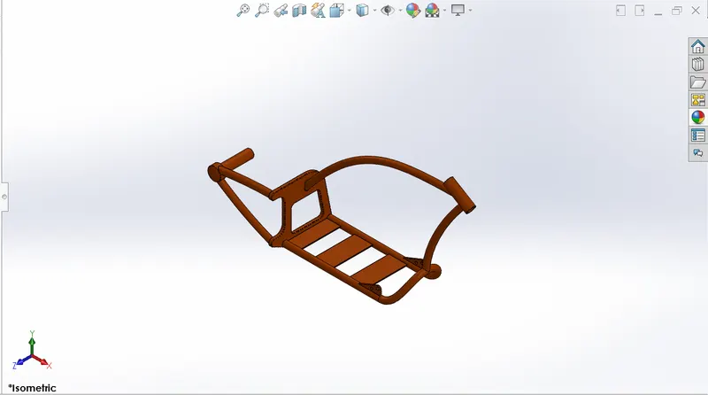
ASSEMBLY
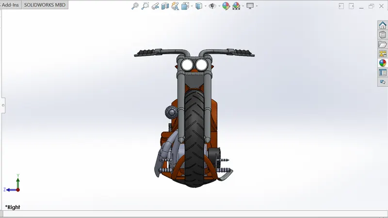
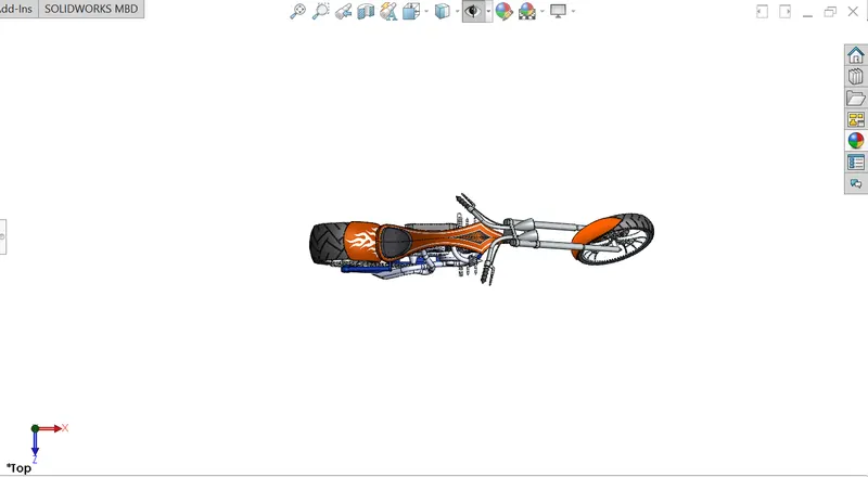
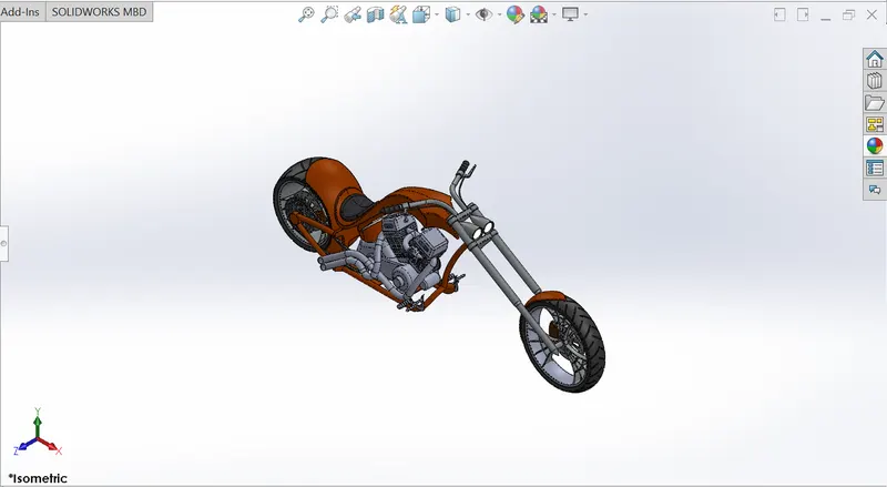
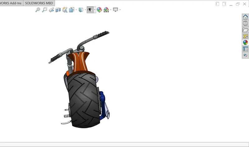
All the modelled parts were inserted one by one in the assembly. The parts were inserted randomly in the assembly environment and were given manual mates by taking chassis as the reference so that all the parts move with respect to chassis only when the chassis floats.
Images of the assembly: Following are the images of the chopper assembly in different views,
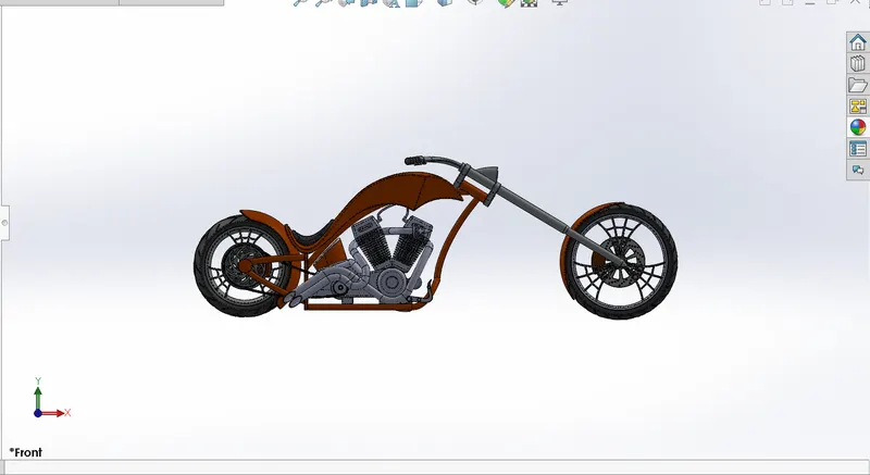
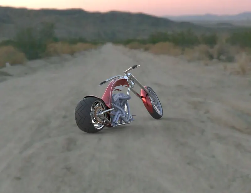
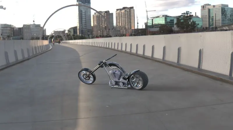
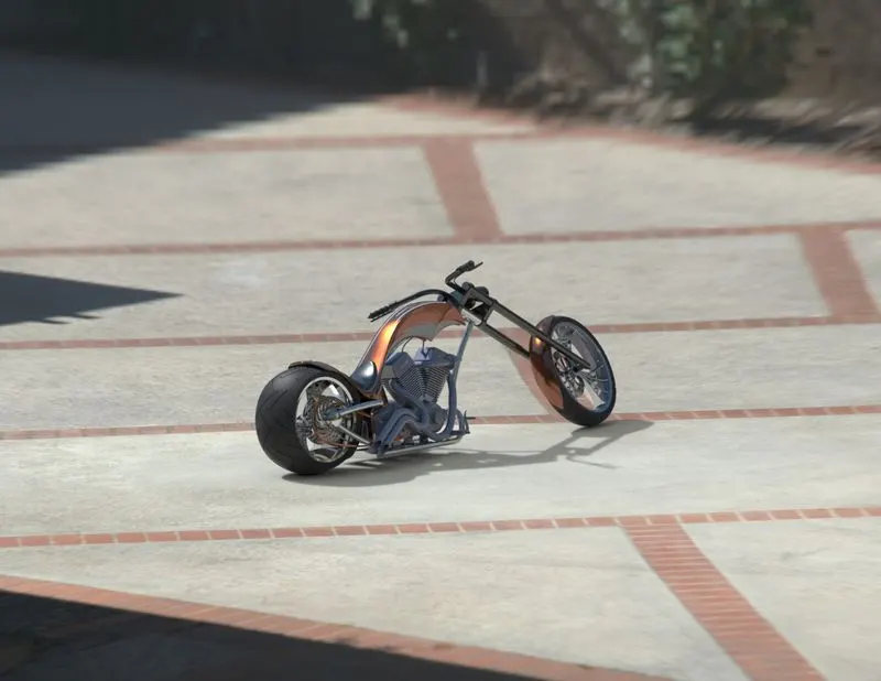
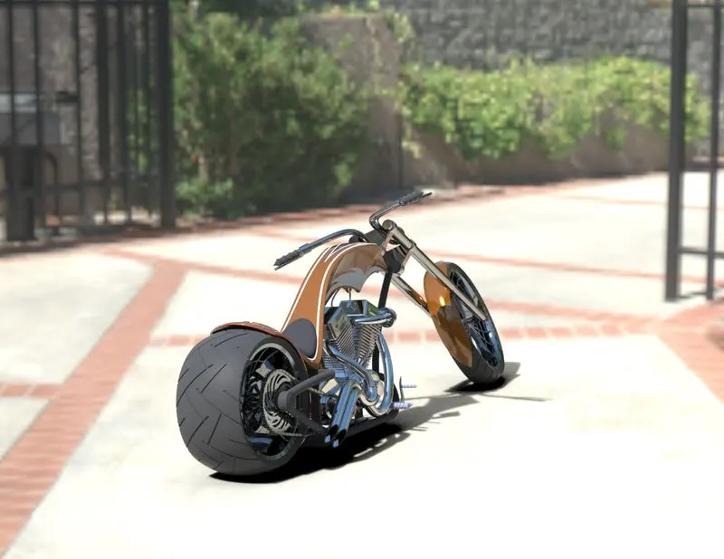
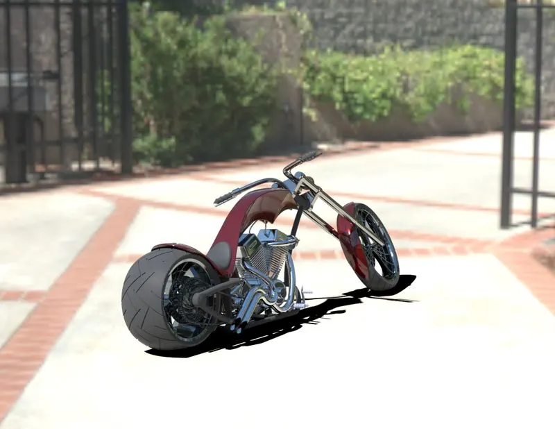
Rendering:- The term rendering comes from the graphic world where a rendering is an artistic drawing of what a new structure would look like. In Computer Aided Design (CAD), a rendering is a particular view of a realistic image. By doing rendering of chopper we get the idea that how it will look into the environment. This rendering is done in the SOLIDWORK Visualize software. By using PHOTOVIEW 360 we can add various camera views to the model, we can set various angles, direction, and can set appropriate distance to get the perfect camera view. In rendering we change color of chopper parts, background images, brightness, rotation and various setting of chopper. Including the resolution and setting number of passes we get more detail visual’s of chopper.
PHOTOREALISTIC RENDERED IMAGES OF AMERICAN CHOPPER
CONCLUSION
All the parts of the American chopper were modelled and the assembly was created using Solidworks and the photorealistic renders of the chopper were created using Solidworks Visualize.