Photo Realistic Rendering
Assembly of Chopper Model
Date: 22-Oct-2021
Objective:
To learn the basic tools and interface in SolidWorks through designing a Chopper. Starting from modeling each part with proper dimensions to its assembly. Then finally render it in SolidWorks Visualize with proper lights and background. Four goals to be completed are:
- Solid Modelling
- Surface Modelling
- Assembly modules
- Rendering for realistic modules
Introduction:
In this project, the design and assembly procedure of the chopper will be explained in detail. The main objective is to master SolidWorks user interface and understand different modelling features. For example, using shell feature for designing gas tank and using projected curve for designing chassis etc. Chopper is divided into parts and they are modelled as per the requirements which is then assembled together at the end. The parts are:
- Front and back fender
- Wheels with rim
- Chassis
- Engine
- Gas and Oil tank
- Chaina and belt
- Pedal
- Front fork
After assembly, the chopper is rendered by adding suitable lights, camera and backplate.
Design Approach:
The design approach to the chopper was taken step by step. Starting from the chopper blueprint to designing, then to assembly and finally rendering. After each step, the design is checked whether it is full dimensioned and whether correct appearance is applied to the part. The flowchart of the design approach is given below:
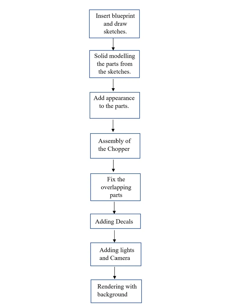
After drawing sketches from the blueprint, solid modelling is done with respect to the requirements. Then necessary paint is applied to each part and after which all the parts are assembled together with mating tools. Later, the imperfections and overlapping parts are fixed. Finally, after adding decals, lights and camera, the assembly is rendered in SolidWorks Visualize by adding suitable background.
The features and properties used in the entire model to design different parts are given below:
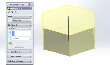
- Extrude Boss: The Extruded Boss is the most basic of all SOLIDWORKS features and extrudes a sketch along a straight-line path to add material. As a sketched feature, it requires a sketch before use. Once the sketch has been created, exit the sketch and select the Features tab of the Command Manager. Then, click the Extruded Boss/Base command. The Property Manager for the Extruded Boss allows you to control starting location, extrude depth and draft for the feature.
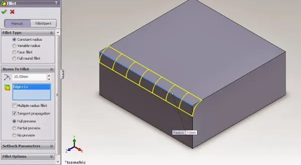
- Fillet: Fillets are classified as applied features, and as such do not require a sketch to be used. Fillets serve to round off edges and/or corners by adding or removing material, depending on whether the edge is internal or external. It should be noted that fillets of different sizes must be created as separate features. Typically, it is best practice to create the largest fillets first and follow with smaller fillets.
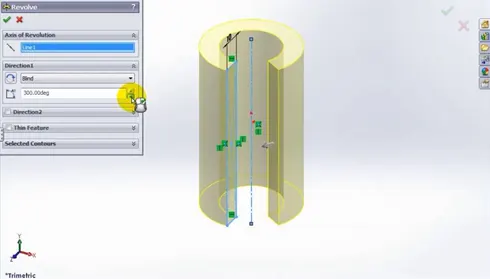
- Revolved Boss Feature: Adds material by revolving a sketch around an axis. Remember, once geometry has been created in your model, any flat face can be used as a sketching surface. It is very important to draw an axis in the sketch which needs to be revolved.
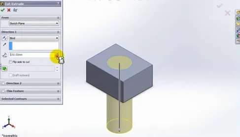
- Extrude Cut: Like the extrude boss feature this feature needs a sketch on the solid body which needs to be cut and the desired shape is then cut off.
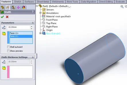
- Shell: SolidWorks shell tool is mainly used for shelling process, in which the material removed from the inner body of model by keeping small thickness and results a hollow model. Using this tool, you can make either completely closed hollowed model or one face opened type.
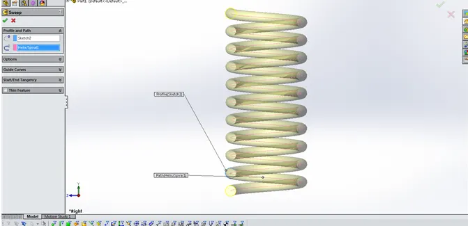
- Sweep Boss / Sweep Cut: Sweep creates a base, boss, cut, or surface by moving a profile (section) along a path, according to these rules: The profile must be closed for a base or boss sweep feature; the profile may be open or closed for a surface sweep feature.
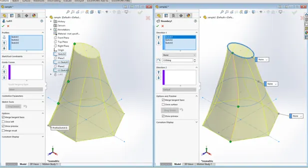
- Loft Boss/ Loft Cut: The loft feature is an important tool for (surface) modelling in SolidWorks. The loft feature creates a shape by making transitions between multiple profiles and guide curves. This tool is very valuable for modelling complex surfaces. You can do some cool stuff when you use this feature properly.
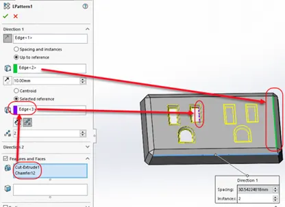
- Linear Pattern: You can use linear patterns to create multiple instances of one or more features that you can space uniformly along one or two linear paths. Pattern instances inherit the visual properties of the original feature when you select Propagate Visual Properties in the Property Manager.
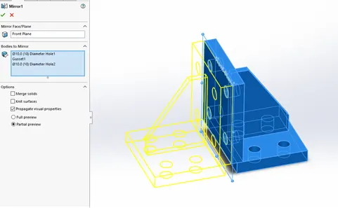
- Mirror: Creates a copy of a feature, (or multiple features), mirrored about a face or a plane. You can select the feature, or you can select the faces that comprise the feature. Bodies to Mirror: Select a body in a single model or multibody part to create a mirror entity. Multibody parts: Apply features to one or more multibody by selecting Geometry Pattern and using Feature Scope to choose which bodies should include the feature.
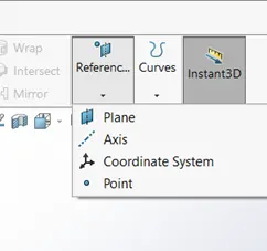
- Reference Geometry: Reference geometry defines the shape or form of a surface or a solid. Reference geometry includes items such as planes, axes, coordinate systems, and points. You can use reference geometry in the creation of several kinds of features.
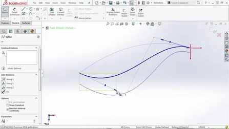
- Projected Curve: You can project a sketched curve onto a model face to create a 3D curve. You can also create a 3D curve that represents the intersection of two extruded surfaces generated by creating sketches on two intersecting planes. You can create multiple closed or open-contour projected curves from a single sketch. You can also use 3D sketches as input for the Projected Curve tool. Note: The Projected Curve tool does not support projections of intersecting curves.
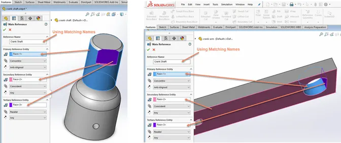
- Mate : Mates create geometric relationships between assembly components. As you add mates, you define the allowable directions of linear or rotational motion of the components. You can move a component within its degrees of freedom, visualizing the assembly's behavior.
-
Some examples include:
- A coincident mate forces two planar faces to become coplanar. The faces can move along one another but cannot be pulled apart.
- A concentric mate forces two cylindrical faces to become concentric. The faces can move along the common axis but cannot be moved away from this axis.
Mates are solved together as a system. The order in which you add mates does not matter; all mates are solved at the same time.
Description:
The chopper model was created by designing each individual part separately and these parts were dimensioned with respect to the blueprints. In this section, all chopper parts will be shown with brief explanation about tools and features used.
- Transmission belt
In this part, “Boss Extrude” feature was used to create the solid body from sketch and “Fillet” feature to smooth the sharp edges. Finally, “Matte Rubber” color was applied for the appearance.
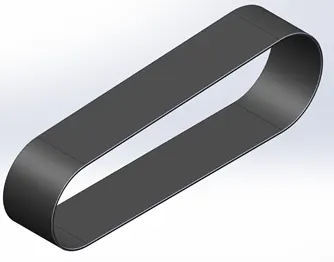
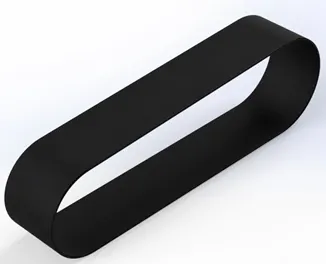
Fig.1: Isometric view of the modelled transmission belt (left) and rendered version (right).
- Rear Fender
In this part, “Revolve” feature was used to create the solid body from the sketch and “Split” feature to round the two ends of the fender. Filter feature was added and “Shell” feature was applied to hollow out the inside of the fender. Finally, “Siena” color was applied for the appearance and flame like decal was added to the upper portion of the fender.
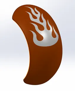
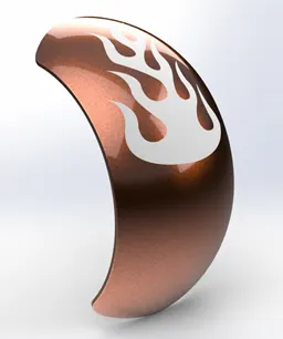
Fig.2: Isometric view of the modelled rear fender (left) and rendered version (right).
- Front Fender
In this part, “Revolve” feature was used to create the solid body from the sketch and “Split” feature to round the two ends of the fender. Fillet feature was applied to round off the sharp edges. Finally, “Siena” color was applied for the appearance.
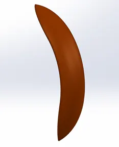
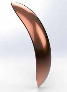
Fig.3: Isometric view of the modelled front fender (left) and rendered version (right).
- Pedal
In this part, “Boss Extrude” feature was used to create the solid body from the sketch and “Fillet” feature to smooth the sharp edges. “Chamfer” feature was used to get a cone shaped end on those pedal extrusions and Linear pattern was used to get the thread like look. Finally, “Chromium Plate” was applied for the appearance.
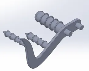
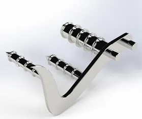
Fig.4: Isometric view of the modelled pedal (left) and rendered version (right).
- Kickstand
In this part, “Loft” feature was used to create the solid body from sketch and “dome” feature to create the rounded face on two ends. “Cut-Extrude” to create a slot to connect with chassis and “Split” feature to create a flat face on the lower end. Finally, “Chromium Plate” color was applied for the appearance.
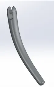
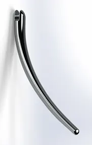
Fig.5: Isometric view of the modelled kickstand (left) and rendered version (right).
- Rear Wheel
In this part, “Revolve” and “Boss Extrude” feature was used to create the solid body of the rim from the sketch and “Cut-Extrude” to create the spoke with the web pattern. Then, “Circular Pattern” was used to create two more web spokes and combined into one body using “Combine” feature. In the same way, rotor and sprocket was created using boss-extrude, cut-extrude and Circular pattern features. Caliper using boss-extrude feature and chamfer is applied on the edges. Tire’s body was made in the same way as rim and the circular pattern is applied on the outer surface after designing a thread. Fillet feature was applied to round off the sharp edges. Finally, “Siena” color was applied for the caliper, “Chromium plate” for rim and sprocket, “Carbon steel” for rotor and “Matte rubber” for tire.
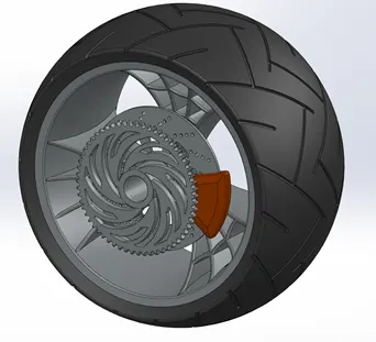
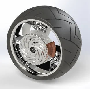
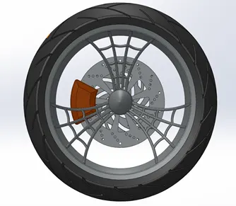
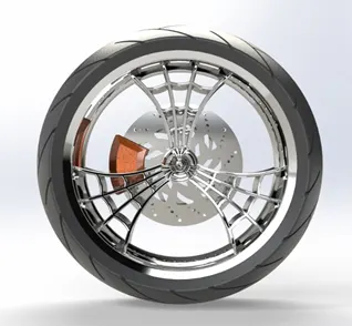
Fig.6: Isometric and side views of the modelled rear wheel (left) and rendered versions (right).
- Front Wheel
In this part, “Revolve” and “Boss Extrude” feature was used to create the solid body of the rim from the sketch and “Cut-Extrude” to create the spoke with the web pattern. Then, “Circular Pattern” was used to create two more web spokes and combined into one body using “Combine” feature.. In the same way, rotor was created using boss-extrude, cut-extrude and Circular pattern features. Caliper using boss-extrude feature and chamfer is applied on the edges. Tire’s body was made in the same way as rim and the circular pattern is applied on the outer surface after designing a thread. Fillet feature was applied to round off the sharp edges. Finally, “Siena” color was applied for the caliper, “Chromium plate” for rim, “Carbon steel” for rotor and “Matte rubber” for tire.
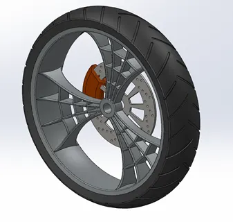
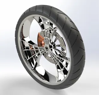
Fig.7: Isometric view of the modelled front wheel (left) and rendered version (right).
- Oil Tank
In this part, “Boss Extrude” feature was used to create the solid body from sketch and “Fillet” feature to smooth the sharp edges. “Shell” feature to hollow out inside of the tank. Finally, “Siena” color was applied for the appearance and white paint on the corners. Decal was added on the middle portion of the side.
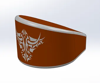
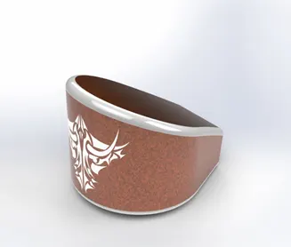
Fig.8: Isometric view of the oil tank (left) and rendered version (right).
- Gas Tank
In this part, “Surface Sweep” feature was used to create the top half of the gas tank and “Surface-Trim” to remove the excess portion. “Curve” feature was used to extract a curve near the front end of the gas tank and first face on the side completed using “Surface-loft” feature. In the same way, the remaining face on the side was created using “Boundary Surface” feature. “Mirror” feature to create another half of the gas tank and stitched together using “Surface-Knit”. “Split-line” and “Surface extrude” features were used to create the seat on the rear of the gas tank. Again, surface loft and boundary surface features were used to close the gas tank form the bottom and knitted together. “Cut-Sweep” feature was used to remove material from the front to accommodate chassis portion and “Shell” feature to hollow out inside of the tank. Finally, “Siena” color was applied for the tank and “Grey cotton” for the seat. Decals were added on the side and top of the tank.
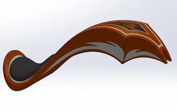
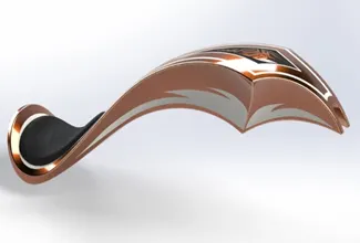
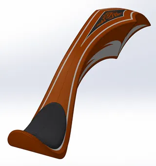
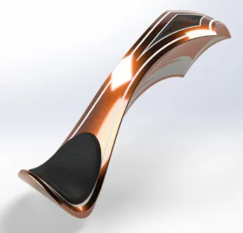
Fig.9: Isometric views of the modelled gas tank (left) and rendered versions (right).
- Chain
First , two chain links were created using boss-extrude feature and then they were used as components with pins to the feature “Curve driven pattern” to create the major portion of the chain. Mirror feature was used to create other side of the chain. Fillet feature was applied to round off the sharp edges. Finally, “Chromium Plate” color was applied for the appearance.
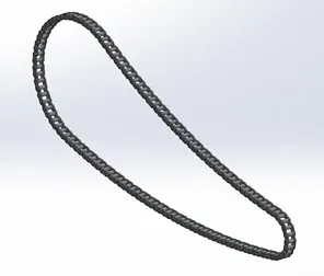
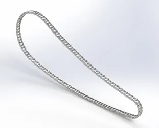
Fig.10: Isometric view of the modelled chain (left) and rendered version (right).
- Front Fork
In this part, “Revolve” and “Boss Extrude” feature was used to create the solid body of the front fork from the sketch and “Linear pattern” was used to create top two plates. Head light was created using “revolve” feature and excess material was removed using “Cut extrude” feature and gave a dome finish at the front. Handlebars and brake/clutch cables were designed using “Curve” and “Sweep” feature. The whole body was mirrored from fork midplane and combined. Finally, “Chromium plate” was plate was applied as appearance for the fork, “Glossy rubber” for grip and cables and “White led” for headlights.
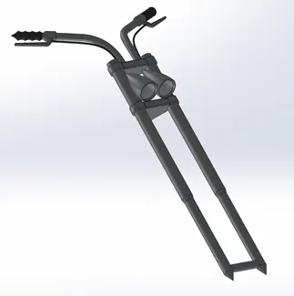
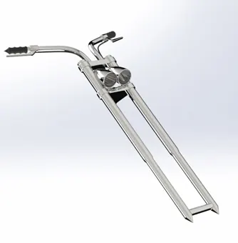
Fig.11: Isometric view of the modelled front fork (left) and rendered version (right).
- Chassis
As mentioned for the previous parts, the major portion of the chassis was designed using features like curve, sweep, cut-extrude, boss-extrude, mirror and split. All added portions were converted to one body using “Combine” feature. Fillet feature was applied to round off the sharp edges. Finally, “Siena” color was applied for the appearance.
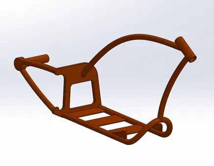
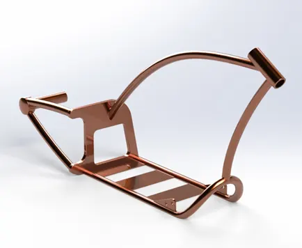
Isometric view of the modelled chassis (left) and rendered version (right).
- Engine
The major portion of the engine especially the lower part was designed using feature like boss-extrude, cut-extrude, revolve, circular pattern, dome, chamfer and fillet. The fins on the side of two-cylinder heads were created using linear pattern feature. “Composite curves” and sweep features were used to design spark-plug wires, tubes from air filter intake and exhaust pipes. All added portions were converted to one body using “Combine” feature. Fillet feature was applied to round off the sharp edges. Finally, “Chromium plate” color was applied for the appearance.
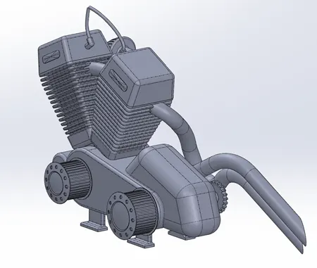
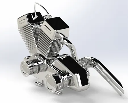
Fig.13: Isometric view of the modelled engine (left) and rendered version (right).
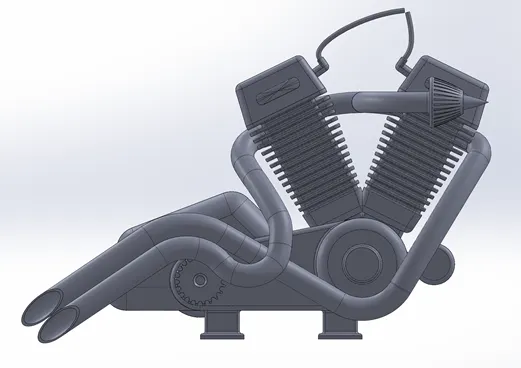
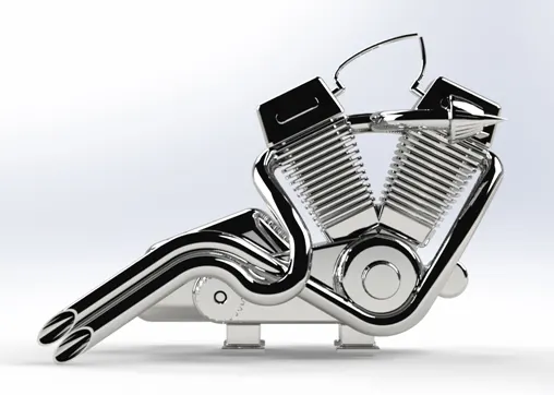
Fig.14: Side view of the modelled engine (left) and rendered version (right).
Assembly Images:
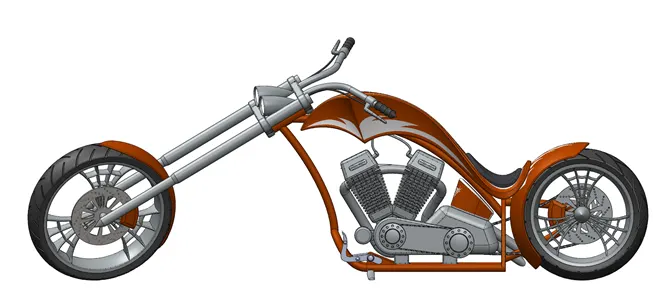
Fig.15: Side view of the American Chopper.
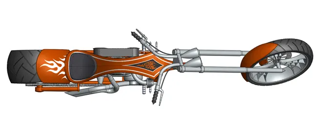
Fig.16: Top view of the American Chopper.
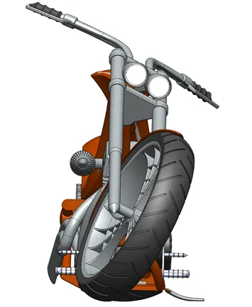
Fig.17: Front view of the American Chopper.
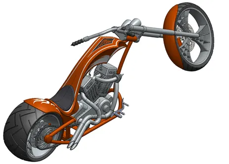
Fig.18: Isometric view of the American Chopper.
Before rendering with the backplate, lights and camera were added to the model. One camera view was added to the chopper assembly with 35mm lens angled from the front as shown below:
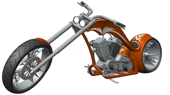
Fig.19: Camera1 view of the American Chopper.
Rendering Images:
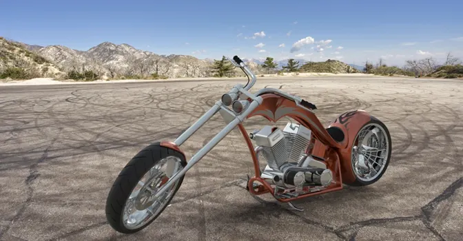
Fig.20: Rendered american chopper assembly with mountain parking lot as backplate.
The same camera view was used in the rendered version with the mountain parking lot as environment and Siena body paint (as shown in Fig.20). The white headlight was replaced with the smoked glass appearance. Decal on the rear fender is also darkened for a different look. Brightness and gamma values are modified to match the assembly with the environment.
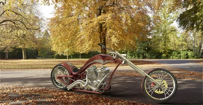
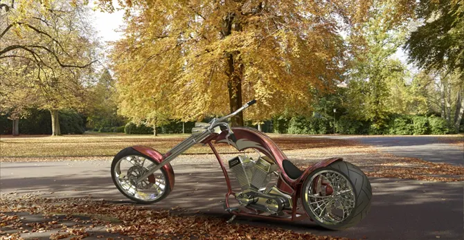
Fig.21: Rendered american chopper assembly with fall trees as backplate.
This fall theme was used in the second rendered model with the views of two sides in the same background (shown in Fig.21). In this rendering, the chopper body paint is changed from “Siena” to “Red Metallic” color.
In this last rendered image shown below, the environment is changed to “Route 66 road” and body paint to “Dark Blue”. Also, for smaller details, the shadows were added to show the direction of sunlight and overall brightness is low due to less sunlight in the scene.
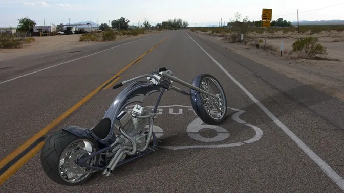
Fig.22: Rendered american chopper assembly with route 66 road as backplate.
Link to all rendered files are given below:
https://drive.google.com/drive/folders/1yoev-oSrMJG99S8LnRJvVoEF6iIML-hy?usp=sharing
Conclusion:
To summarize, this American chopper project was beneficial to learn basic tools and master SolidWorks interface quickly. Concepts learned from this project are solid modelling, surface modelling, assembly and rendering for realistic modules. Also mastered advanced features like composite curves, surface loft, boundary surface, surface knitting, sweep etc. Finally, rendered the assembly in SolidWorks Visualize with realistic backplates and environment.