Photo Realistic Rendering
SKILL LYNC
PROJECT REPORT MODELLING OF
AMERICAN CHOPPER ON SOLIDWORKS
REPORT CREATED BY,
VIGNESH D
Introduction of American Chopper
An American chopper employs radically modified the steering angle and
lengthened forks for a stretched-out appearance. The main characteristic features
of chopper are long front ends with extended forks often coupled with increased
rack angle, hard tail frames.
Design Methodology:
1. Create a new part file using (MMGS) unit
2. Assemble the designed components
3. Apply materials, paint and decals
4. Render the final mode
Sketch commands
➢ Line: In sketch line is created by choosing different types like centreline,
midpoint line and construction line.
➢ Arc: It is a three-pointed arc can be created on basis of positioning points.
➢ Smart dimension: the dimension of any sketches can be easily at required
situation easily by using.
➢ Ellipse: An ellipse is a geometrical shape that results from viewing a
circular shape in perspective, from a different point.
➢ Circle: Circle is sketching tool in Solidworks. There are two methods of
drawing circle, centre circle and perimeter-based circle.
➢ Sketch Picture: This command is useful in inserting required picture for
modelling part. When we inserting picture the scale tool automatically
displays. Then use the scale tool to resize the picture.
➢ Offset: it is offsets one or more sketch entities, selected model angles or
model face by specifying its distance.
➢ Construction lines: it is useful to convert continuous line into dashed line,
as well as we can create a line with infinite length without length
parameter.
➢ Rectangle: The centre rectangle point centre rectangle can be controlled
easily by using construction lines to midpoint.
➢ Slots: it is used to develop 4 different types of slots with the reference of
the central axis by adding dimensions straight slot and centre point and
centre point straight slot.
➢ Spline: It is to develop irregular shape objects by assigning several fit
points.
➢ Trim: select the trim type based on the entities to delete unwanted
geometry.
➢ Extend: It can extend the entities near by geometry on the basis of required
selection.
➢ Patterns: Mainly in the sketch pattern are classified into two types
namely,
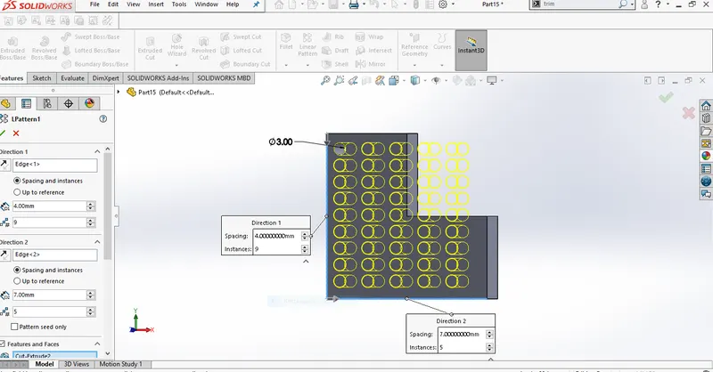
1. Linear pattern: A linear pattern crates a copy of a feature similar
to a grid. The required things are specifying the direction of the
pattern, the number of copies in each direction, distance between the
copies.
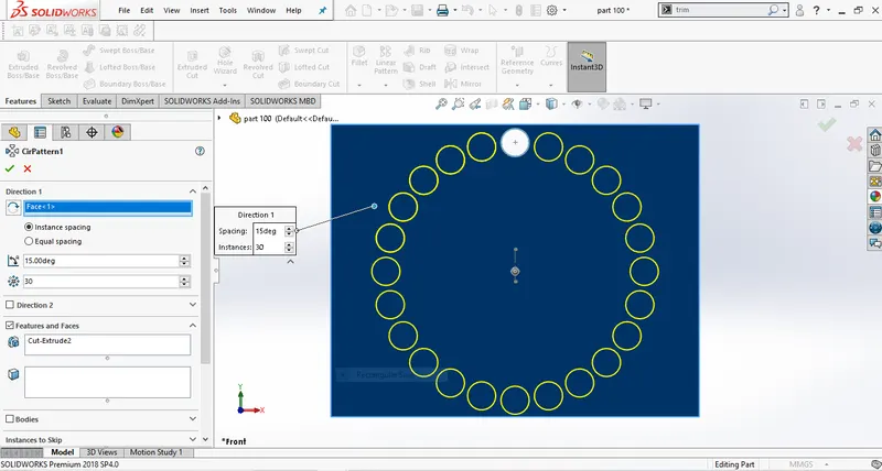
2. Circular pattern: The circular pattern is very similar to the linear
pattern, instead of patterning along dimensions, it patterns is about
axis.
Feature commands
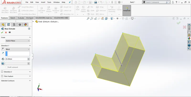
➢ Extrude boss: This feature is used to develop solid with reference of
sketch contours in one or both directions.
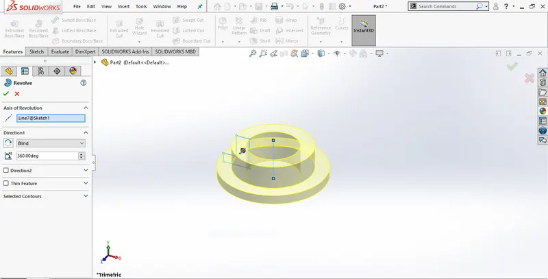
➢ Revolve boss: It is used to create a solid feature by revolving a sketch
about an axis. It is mostly used for creating a cylinder, pipes and tubes
which on axis.
➢ Loft: it creates a feature by making a transition between profiles. A loft
can be a base, boss, cut and surface. It can be possible to create a loft using
two or more profiles.
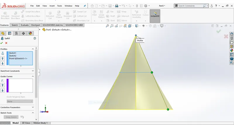
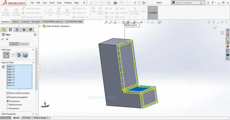
➢ Fillet: it creates a round internal and external face on the part. It is possible
to fillet all edges of a face, selected set of faces, selected edges.
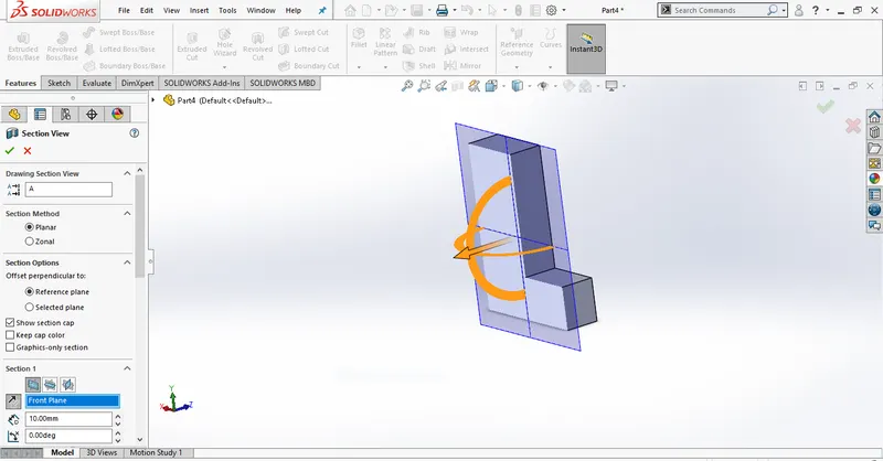
➢ Selection view: In a section view for part or assembly document, the model
is displayed as if cuts by planes and face that to specify.
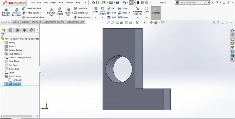
➢ Extrude cut: It is a tool used to remove material by projecting a sketched
section normal to the sketching planes.
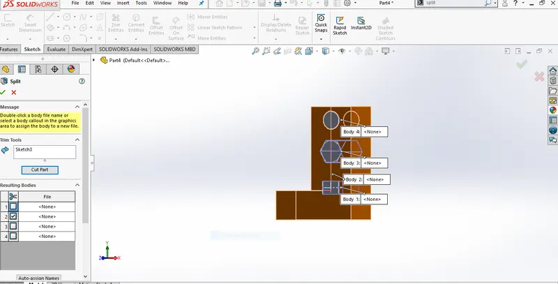
➢ Split: This feature is used to create multiple parts from an existing part. It
is possible to split one or more surface bodies. To split a sketch, the
trimming sketch extends past the boundaries of sketch to split.
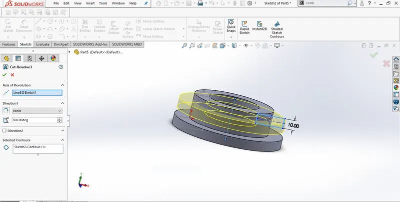
➢ Revolved Cut: This feature helps to remove materials from 3Dmodels
possess axis symmetry. Revolved cut removes materials by revolving a
closed profile an along it's an axis.
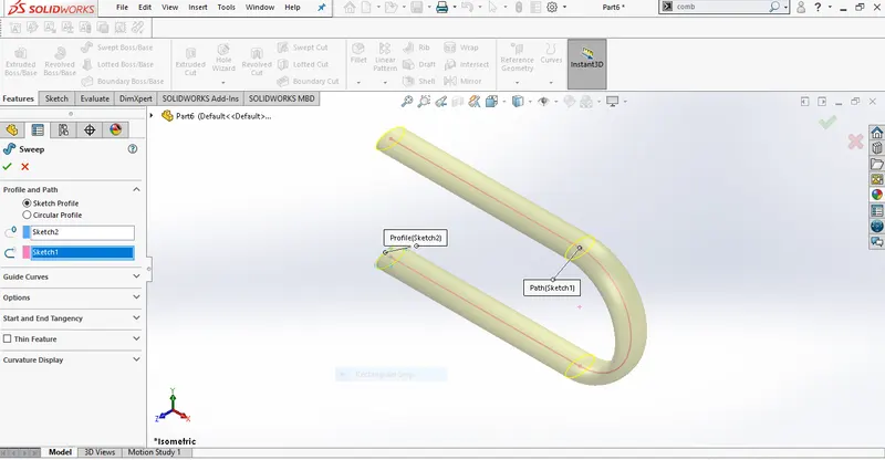
➢ Sweep Boss: It creates a base by moving a section along the path,
according to this profile must be closed for a base feature.
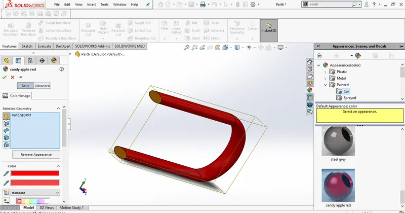
➢ Appearance: This feature has capability to control the way in which
the surface of model to look. This is applied at part, assembly, feature
and face of model.
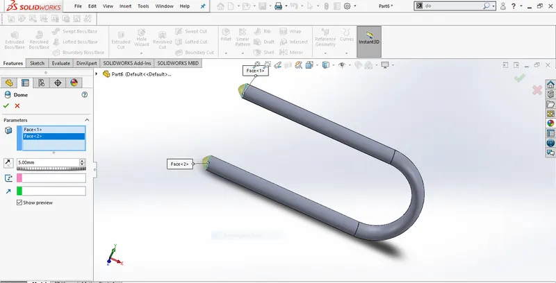
➢ Dome: This feature is used to create one or more dimes to the selected
planer and non-planer faces.
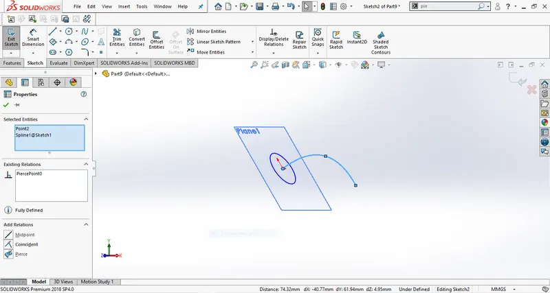
➢ Pierce relationship: These relations can be added to sketch points and
an axis, edge, line. They are especially useful for ensuring that a
coincident relationship is formed between entities of varying axis.
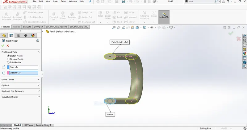
➢ Sweep cut: It is a feature tool, mainly used to cut a solid model by
sweeping a completely closed profile along an open or closed path. To use
swept cut, we should need a closed profile and open or closed path, which
may be line, helix, and circle, rectangular.
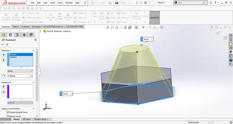
➢ Boundary: These tools produce very high quality, accurate feature useful for
creating complex shapes for markets focused on consumer product design,
medical, aerospace.
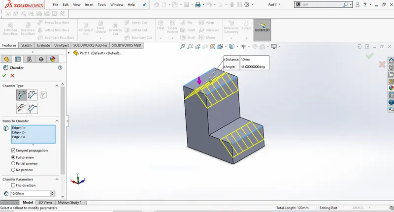
➢ Chamfer: It is used for assigning smooth edges on solid with five
different methods such as angle-distance, Distance-distance, offset
face, face-face and vertex.
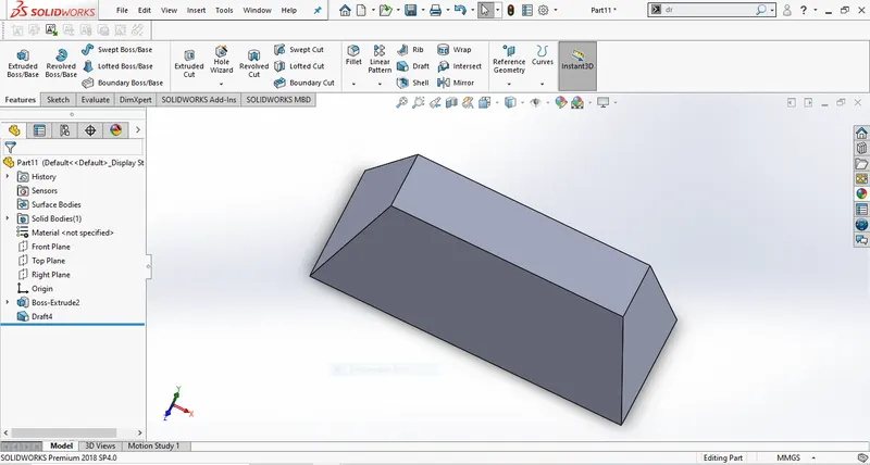
➢ Draft: Draft tapers face using a specified angle by selecting faces in the
models.
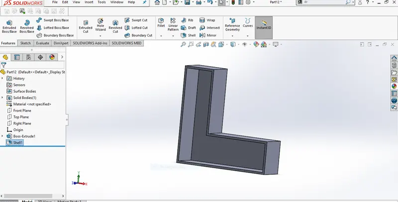
➢ Shell: The shell tool hollows out a part, leaves open the face that is
selected the remaining facers and creates thin-walled features on it.
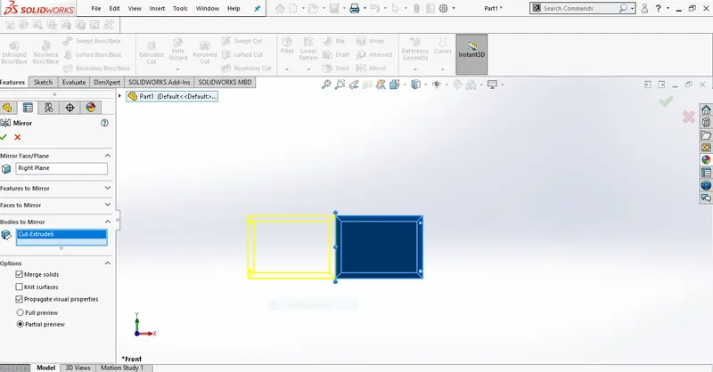
➢ Mirror: It can create a duplicate object at required planes and surface.
➢ Composite curve: This feature can create a composite curve by
combining required curves, sketch geometry, model edge in to single
curve.
➢ Blocks: This command is a saved sketch that can prevent redrawing the
same sketch at multiple times.
➢ Combine: This Common function allows us to add two bodies together
and keep the area that is common to them.
➢ Sketch plane: To develop solid from sketch plane with specific distance.
Surface commands
➢ Sweep surface: Theses surface are generated from a section curve
positioned along a path. Various sweep types are available to extend the
sweep surfaces.
➢ Trim surface: It is possible to use a surface, plane, sketch as a trim
tool to trim intersecting surface.
➢ Surface Loft: These surfaces are generated by multiple 3D Curves or existing
edges creating a smooth tangency between the selected curves. Match points
are created between each selection denoting the orientation and path of
the loft surface.
➢ Projected Curve: It is a tool used to form 3D curves from to 2D curves
from two different planes.
➢ Knit Surface: The knit surface tool is used to combine two or more
faces.
American Chopper Parts
1. Transmission Belt
2. Kickstand
3. Chain
4. Front Fender
5. Rear Fender
6. Front Fork
7. Chassis
8. Front Wheel
9. Rear Wheel
10. Oil Tank
11. Engine
12. Gas Tank
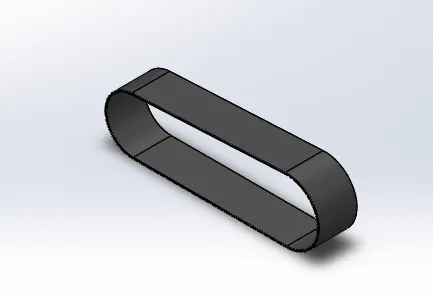
1) Transmission belt
Transmission belt is commonly used in bike to connect gear box
driven to rear wheel driven pulleys to take control of speed. In this case the
transmission belt is designed using the following features
|
Command in sketch |
Command in features |
|
1. Line |
1. Plane |
|
2. Arc |
2. Boss extrude |
|
3. Smart dimension |
3. Fillet |
|
4. Properties |
4. Appearance |
|
5. Offset Entities |
2) KICKSTAND
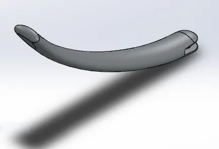
Kickstand is the common part in all the bikes which is used to support the
bike to stand in the ground. Basically, the kickstand must be designed in a way has
to be firm in the ground. The design must be sure that the kickstand is strong and
firm enough and not slippery to the ground.
|
Command in sketch |
Command in features |
|
1. Line |
1. creating plane |
|
2. Splines |
2. Loft |
|
3. Ellipses |
3. Dome |
|
4. Circle |
4. Extrude cut |
|
5. Smart dimension |
5. Split |
|
6. Extrude boss |
|
|
7. Fillet |
3) CHAIN
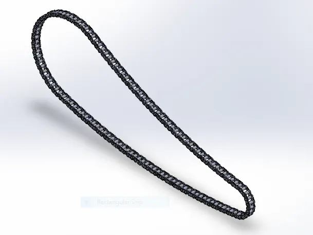
The power transmission chain is the important part in most of the
mechanism which is used to transmit power from one part to another. In
motorcycle it carries the power produced from the engine to rear wheel used
to drive the motorcycle. The features used in chain design after sketches are.
|
Command in sketch |
Command in features |
|
1. Circle |
1. Extrude boss |
|
2. Line |
2. Blocks |
|
3. Properties |
3. Linear pattern |
|
4. Arc |
4. Fillet |
|
5. Trim |
5. Mirror |
|
6. Appearance |
4) FRONT FENDER
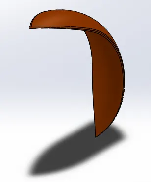
The front fender is an outside portion covers over the front tire to protect
the bike from throwing sand, mud, stones and other dirt to the rider. In this
case Front fender is designed using the following features
|
Command in sketch |
Command in features |
|
1. Line |
1. Axis |
|
2. Arc |
2. Revolve |
|
3. Properties |
3. Split |
|
4. Smart dimensions |
4. Fillet |
|
5. Offset entities |
|
|
6. Trim |
|
|
7. Extend |
|
|
8. Splines |
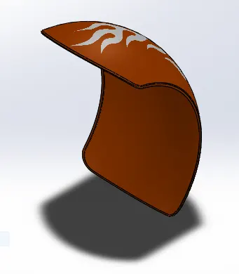
5) REAR FENDER
The rear fender is an outside portion covers over the rear tire to protect the bike
from throwing sand, mud, stones and other dirt to the rider. In this case Front
fender is designed using the following features
|
Command in sketch |
Command in features |
|
1. Line |
1. Axis |
|
2. Arc |
2. Revolve |
|
3. Properties |
3. Fillet |
|
4. Smart dimensions |
4. Shell |
|
5. Offset entities |
5. Appearance |
|
6. Trim |
|
|
7. Extend |
|
|
8. Splines |
6) FRONT FORK
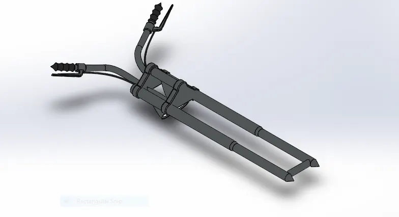
Front fork in the motorcycle is the huge part where it allied with many front
parts such as front wheel, handle, headlights and more. It ultimately controls the
direction of the bike by the rider. It is especially important for front fork to be
stable and should be designed in detail. In this case, to design a front for the
following features are used.
|
Command in sketch |
Command in features |
|
1. Line |
1. Extrude boss |
|
2. Arc |
2. Extrude cut |
|
3. Splines |
3. Revolve |
|
4. Properties |
4. Linear pattern |
|
5. Fillet |
5. Revolve cut |
|
6. Circle |
6. Combine |
|
7. Offset |
7. Fillet |
|
8. Convert entities |
|
|
9. Mirror |
|
|
10. Trim |
7) CHASSIS
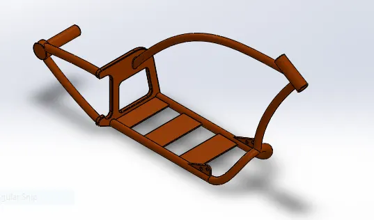
Chassis is particularly important part in all kinds of vehicles and commonly
known as skeleton of the vehicle. It holds many components or parts of the body
and completes the vehicle structure. Here the features that are used to model a
chassis.
|
Command in sketch |
Command in features |
|
1. Spline |
1. Sweep |
|
2. Circle |
2. Mirror entities |
|
3. Lines |
3. Extrude boss |
|
4. Sketch picture |
4. Extrude cut |
|
5. Arc |
5. Chamfer |
|
6. Fillet |
|
|
7. Plane |
|
|
8. Dome |
|
|
9. Split |
|
|
10. Combine |
|
|
11. Revolve boss |
|
|
12. Curves |
|
|
13. Appearance |
8) FRONT WHEEL
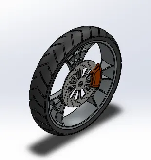
Wheels are the major component of the vehicle which it sustains the entire
loads and carries it. The important features that are used in wheel parts are listed.
|
Command in sketch |
Command in features |
|
1. Line |
1. Extrude boss |
|
2. Arc |
2. Extrude cut |
|
3. Spline |
3. Revolve |
|
4. Properties |
4. Linear pattern |
|
5. Fillet |
5. Revolve cut |
|
6. Circles |
6. Combine |
|
7. Offset |
7. Fillet |
|
8. Convert entities |
|
|
9. Mirror |
|
|
10. Trim |
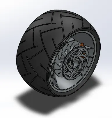
9) REAR WHEEL
Wheels are the major component of the vehicle which it sustains the entire
loads and carries it. The important features that are used in wheel parts are listed.
|
Command in sketch |
Command in features |
|
1. Line |
1. Extrude boss |
|
2. Arc |
2. Extrude cut |
|
3. Spline |
3. Revolve |
|
4. Fillet |
4. Linear pattern |
|
5. Mirror |
5. Revolve cut |
|
6. Circles |
6. Combine |
|
7. Offset |
7. Fillet |
|
8. Convert entities |
8. Chamfer |
|
9. Trim |
10) OIL TANK
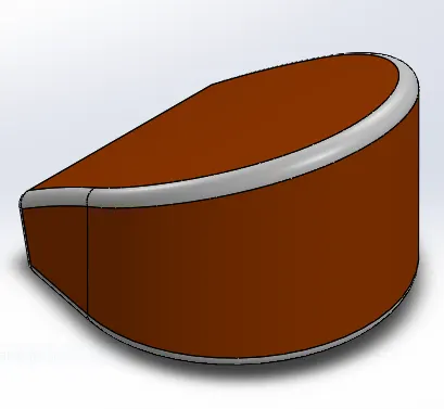
Oil tank generally used to store the oil feeds to the engine parts for
lubrication. The design of oil tank includes the following features.
|
Command in sketch |
Command in features |
|
1. Line |
1. Extrude boss |
|
2. Properties |
2. Combine |
|
3. Fillet |
|
|
4. Shell |
|
|
5. Appearance |
11) ENGINE
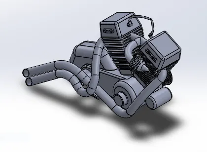
Engine is the important component and also called as Heart of the vehicle
where it produces required power to drive a vehicle. Engine is most complicated
component consists too many fixtures and parts. While designing the engine, it is
important to choose the dimensions and location to connect other sub parts of the
engine. In this case the following features are used to design an engine component
after sketching follows.
|
Command in sketch |
Command in features |
|
1. Sketch picture |
1. Extrude boss |
|
2. Circle |
2. Fillet |
|
3. Spline |
3. Plane |
|
4. Lines |
4. Circular pattern |
|
5. Properties |
5. Dome |
|
6. Arc |
6. Extrude cut |
|
7. Chamfer |
|
|
8. Fillet |
|
|
9. Sweep |
|
|
10. Mirror entities |
|
|
11. Combine |
|
|
12. Curves, Split |
12) FUEL TANK
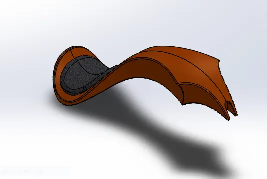
Fuel tank is common part in all kinds of vehicles running by fuel.
Following that, the final part of the motorcycle includes the fuel tank where the
only part focusing on surface design rather than other components of the bike.
The features used to design the fuel tank followed by
|
Command in sketch |
Command in features |
Command in surfaces |
|
1. Lines |
1. Planes |
1. Sweep surface |
|
2. Splines |
2. Mirror entities |
2. Trim surface |
|
3. Sketch picture |
3. Sweep cut |
3. Surface loft |
|
4. Convert entities |
4. Shell |
4. Projected curve |
|
5. Offset |
5. Boundary surface |
|
|
6. Arc |
6. Knit surface |
|
|
7. Trim |
7. Split line |
|
|
8. Extrude surface |
||
|
9. Fillet |
ASSEMBLING THE PARTS OF AMERICAN CHOPPER
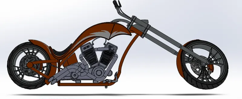
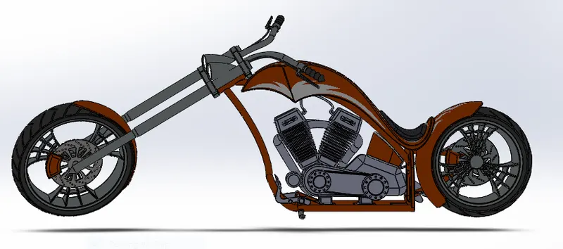
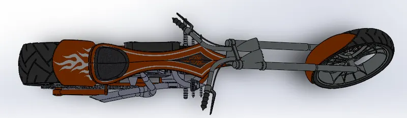
Assembling of bike starts after completing the design of individual parts.
In the assembly, the chassis of the bike is mounted initially, and other parts are
assembled with relation to the planes of Chassis to follow up. The image of
completely Assembled bike is attached below.
Features used to assemble chopper
• Mates
• Insert part
Mates
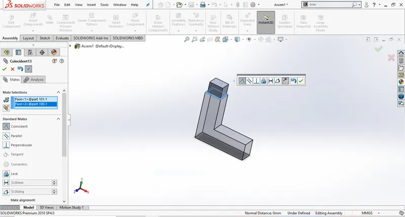
Mates create geometric relationship between assembly components. As we
add mates, we define the allowable direction of linear or rotational motion of the
components to move a component within degrees of freedom, visualising
assembly behaviour.
FRONT SIDE VIEW
BACK SIDE VIEW
TOP SIDE VIEW
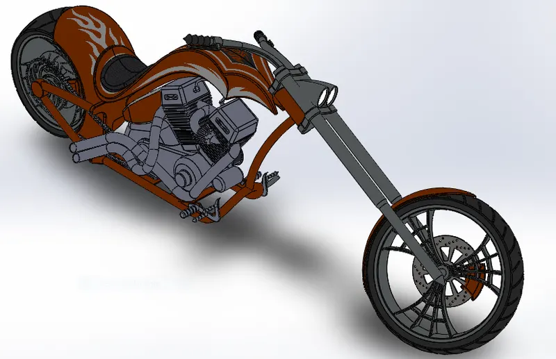
ISOMETRIC VIEW
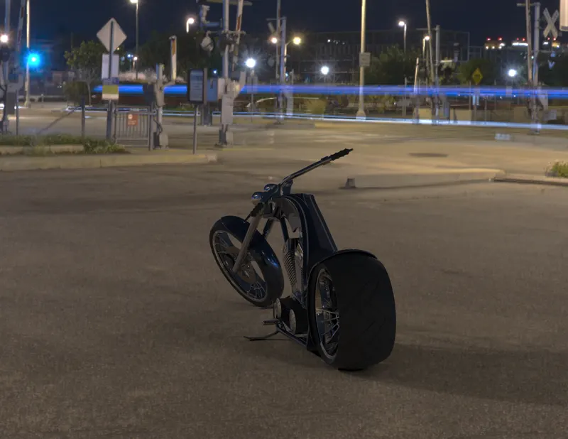
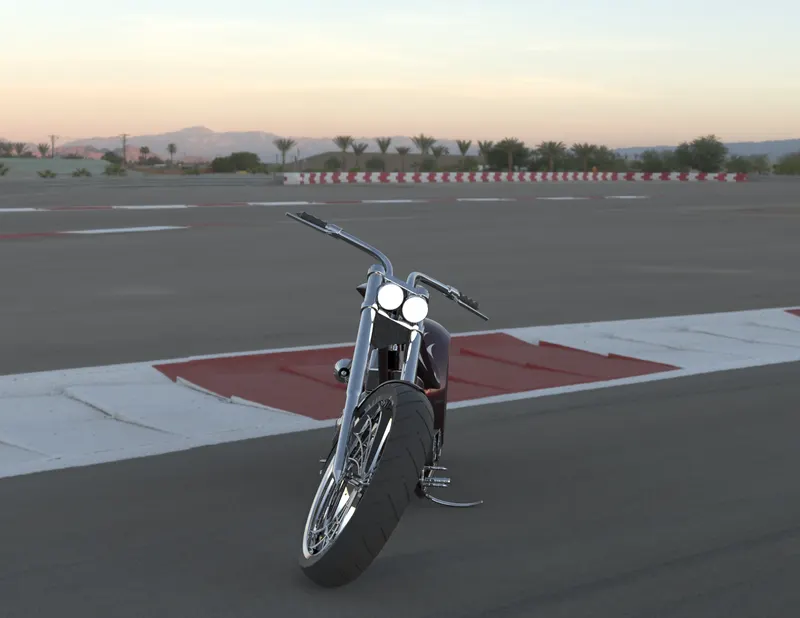
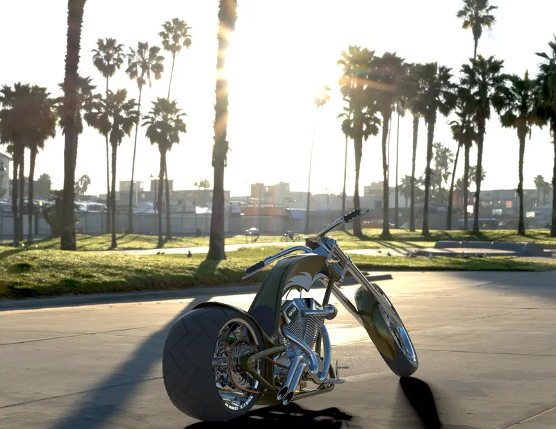
ADDING ENVIRONMENT, LIGHTS AND CAMERAS
After adding the decals, it’s time for the chopper model to setup in an
environment. Adding lights under different conditions and setting up the model
in different camera angle are done for the convenience of the Designer. There are
lot of Environment, lights and camera options are available in Solidworks
according to the character of the model. The following images are attached in
different camera angle and lights.
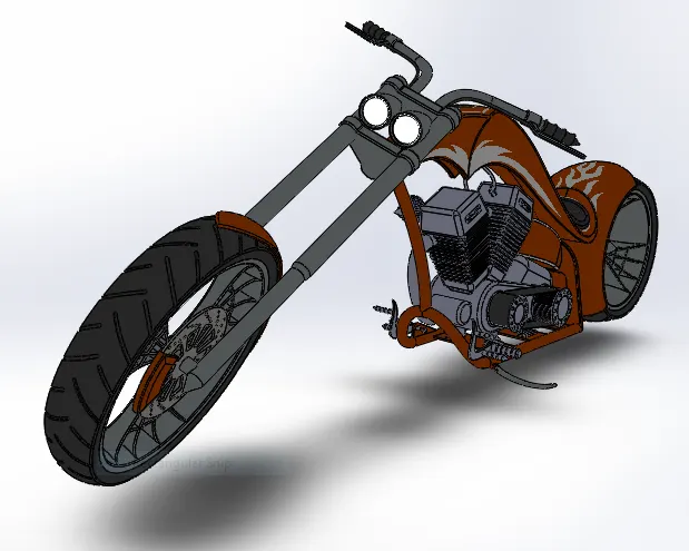
CAMERA VIEW
RENDERING:
• Rendering is the process of creating realistic images of the Photorealistic
model with the environment.
• Rendering has been done in two ways in solidworks. The following are
the two ways,
➢ Photoview 360
➢ Solidworks Visualize
• In the photorealistic model some of the mate conditions and positions are
changed to render realistic models.
• Then the photorealistic model is rendered into realistic images with
different views.
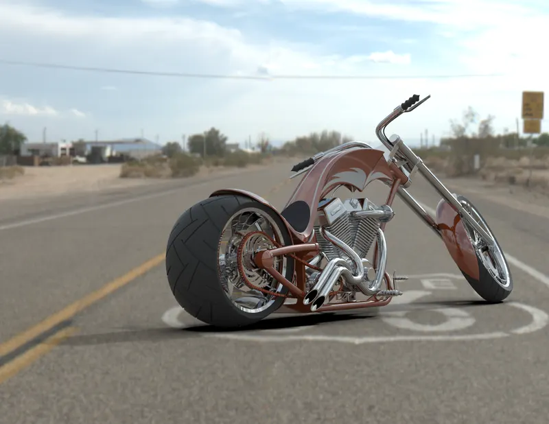
RT66
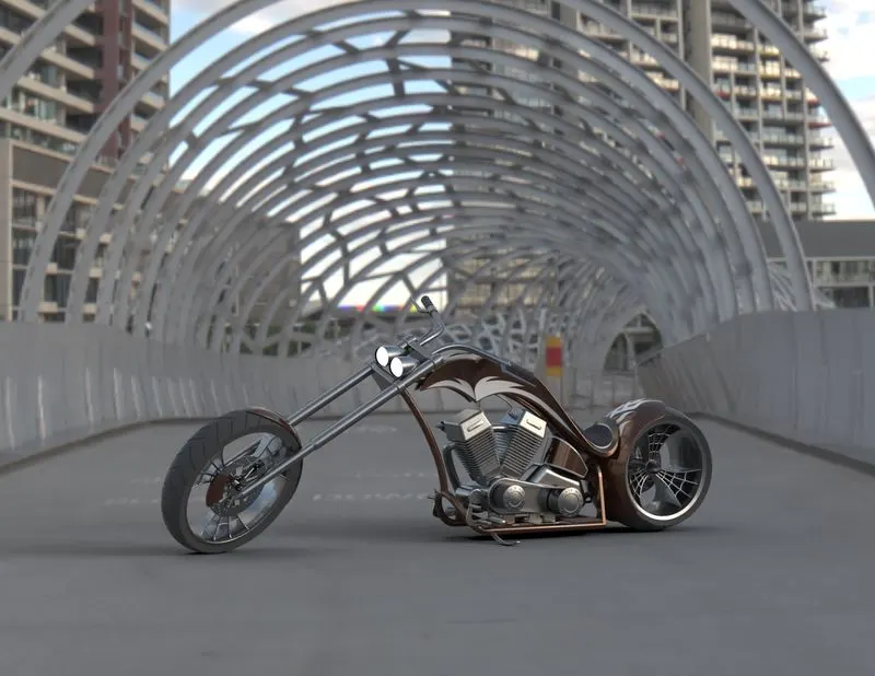
DOCKLAND BRIDGE
INDUCTRAIL
RACE TRACK
VENICH BEACH
CONCLUSION
In the project , The modeling of the individual part of chopper and assembled by using
the feature on solidworks. Decals were added to the repected body.the environment and
scene were imported to make a chopper look realistic and digital.