Photo Realistic Rendering
Project Title: Modeling and Photo realistic rendering of American chopper.
Objectives:
- The main objective of this project is to model fully American Chopper assembly in solidworks and to render the model using Solidworks Visualize.
- To learn different tools and shortcuts to make modeling easier.
- To understand and work on different projects to build a great interest in design.
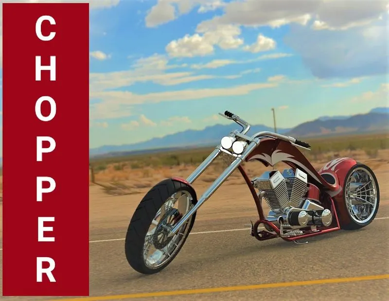
Fig 1. Rendered Image of American chopper.
I. Introduction.
Solidworks is the most widely used designing software across the world. American chopper is the pictographical modeling project where Skill Lync supported us to learn each and every aspects of the software such as part modeling, assembly from parts, extracting part from 3D to 2D drawing file. Software Tools such as Features involving extrude boss, revolve boss, extrude cut, trim, offset, loft, fillet, chamfer, mirror, planes and curves along with sketch tools. Designing is nothing but creativity, which can be only possible through sepcial tools such as blocks, projected curves, curve driven pattern, inserting .png image into drawing, 3D Sketch, spline tool, swept boss.etc.
II. Part Modeling:
In Part modeling we need to sketch the 2d drawing which must be fully defined and to be converted to 3d model using feature tools in solidworks.
III. Parts modeled for chopper:
- Transmission Belt
- Kick Stand
- Front Fender
- Rear Fender
- Oil tank
- Chain
- Pedal
- Front Wheel
- Rear Wheel
- Front Fork
- chassis
- Engine
- Gas Tank.
1.Transmission Belt.
Transmission belt plays very important role in power transmission from engine to gear box respectively to the wheels.
Belt description; a) Type of belt; Flat belt. b)Centre distance; 350mm
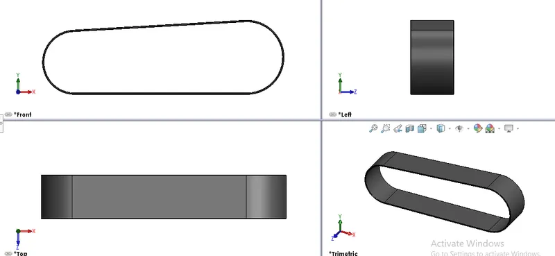
Fig 2. Different views of Transmission Belt.
Features used to create a transmission belt,
- Sketch- The sketch is a two-dimensional representation of the model. there are different sketch options in solidworks like line, arc, circle, rectangle, spline, these are known as entities.
- Offset- To offset one or more entities known as chain with some distance .
- Extrude boss- Extrude is a option used to convert 2D sketch to 3D model.
- Fillet- Fillet/Round creates the rounded internal or external face of the part.
- Appearance- In this section aesthetic changes can be made in part or model.
Design Methadology,
- Open solidworks > New Part > start modeling.
- Before creating the sketch change the name of the plane as Front plane > Front plane transmission belt Top plane > Top plane transmission belt Right plane > Right plane transmission belt .
- Then select Front plane > Edit sketch
- 2D sketch to be created on plane by giving accurate dimensions with fully defined.
- Exit sketch > Features > Extrude boss/base.
- To add fillet to the model goto Features > Fillet > Enter Radius > Select the corners to be filleted.
- Save the model as " Transmission Belt".
2. Kickstand.
The kickstand is used to support the chopper, It is also known as side stand.
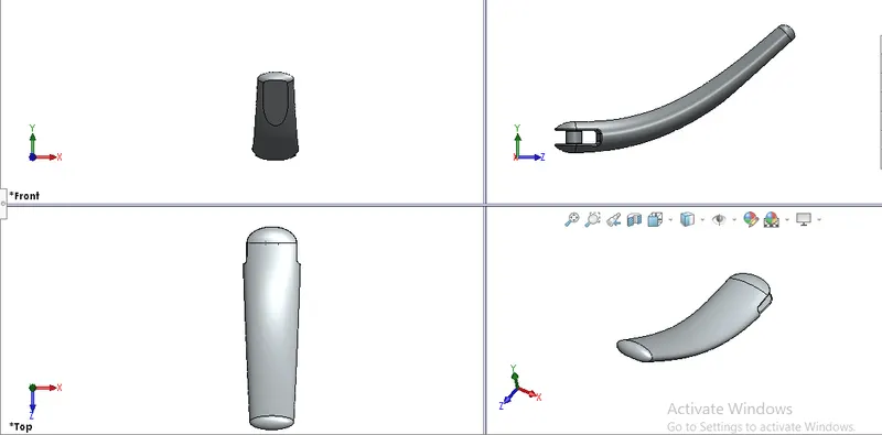 Fig 3. Different views of Kickstand
Features used to create kickstand:
- Sketch- The sketch is a two-dimensional representation of the model. there are different sketch options in solidworks like line, arc, circle, rectangle, spline, these are known as entities.
- Loft- The Loft feature in solidworks allows us to generate conplex geometry in a single feature. It does this by interpolating surfaces between various cross section of a model. These cross-section can be sketches, faces, or edges. In the loft-interface these cross section are considered as "Loft Profiles".
- Dome- This feature can be created on planar or non planar faces whose centroid lies outside the face.
- Extrude Boss- Extrude boss is a option used to convert 2D sketch to 3D model.
- Extrude cut- This feature helps to remove material from 3D model.
- Fillet- Fillet/Round creates the rounded internal or external face of the part.
- Split- This feature helps in splitting a part into two parts by a line which can be used to remove part and do the operation.
- Appearance- Improves the asthetic feature in a model.
Design Methadology,
- Open solidworks > New Part > start modeling.
- Before creating the sketch change the name of the plane as Front plane > Front plane Top plane > Top plane Right plane > Mid plane
- Mid plane > Edit sketch
- Create fully defined sketch with Spline and trim commands.
- Project curves > Planes add two new planes and sketch an ellipse independently in each plane.
- Loft > Select both elipse from two planes along with guide curves.
- Split Kickstand and remove one part of split to make flat surface to kickstand.
3. Front Fender.
Front fender is a part mounted on the fork above the wheel to protect the rider and chopper other parts from the debris and foreign particles.
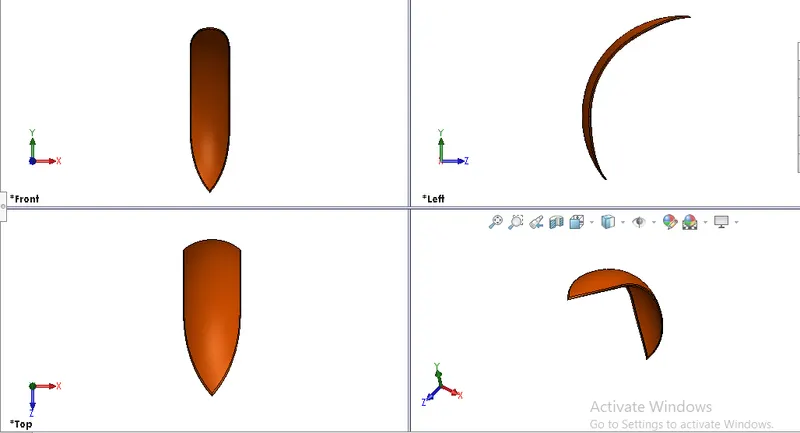
Fig 4. Different views of Front Fender.
Features used to create Front fender:
- Sketch- The sketch is a two-dimensional representation of the model. there are different sketch options in solidworks like line, arc, circle, rectangle, spline, these are known as entities.
- Offset- To offset one or more entities known as chain with some distance.
- Trim entities- Trim is a type of feature having two options either trim or Extend, amonst them most used command is power trim.
- Revolve- To create a revolve feature , create sketch contains one or more profile and a centerline, line, edge to use as the axis around which the feature revolve can bbe used.
- Dynamic mirror- Entites can be mirrored about a plane or a face.
- Split- This feature helps in splitting a part into two parts by a line which can be used to remove part and do the operation.
- Fillet- Fillet/Round creates the rounded internal or external face of the part.
- Appearance- Improves the asthetic feature in a model.
Design Methadology,
- Open solidworks > New Part > start modeling.
- Front plane > Edit sketch >
- Then to revolve sketch about its axis, goto Features > Revolve > Select sketch >Direction1. 5° and Direction2. 130°.
- To remve unwanted part Top plane > Sketch > Split > Cut part.
- Fillet on all corners of Ø6mm.
- Apperance goto Apperance > Painted > Car > siena.
4. Rear Fender.
The use of rear fender is to protect rear wheel from mud and debris, fender is mouned on the chassis to protect rear wheel.
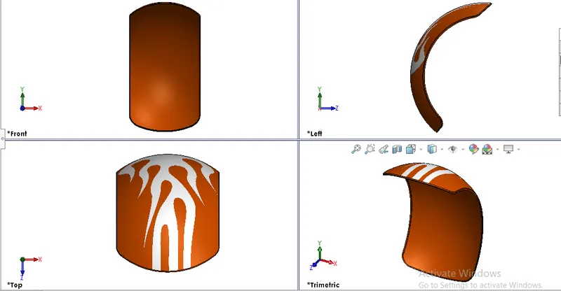
Fig 5. Different views of rear fender.
Features used to create Rear fender:
- Sketch- The sketch is a two-dimensional representation of the model. there are different sketch options in solidworks like line, arc, circle, rectangle, spline, these are known as entities.
- Offset- To offset one or more entities known as chain with some distance.
- Trim entities- Trim is a type of feature having two options either trim or Extend, amonst them most used command is power trim.
- Revolve- To create a revolve feature , create sketch contains one or more profile and a centerline, line, edge to use as the axis around which the feature revolve can bbe used.
- Dynamic mirror- Entites can be mirrored about a plane or a face.
- Split- This feature helps in splitting a part into two parts by a line which can be used to remove part and do the operation.
- Fillet- Fillet/Round creates the rounded internal or external face of the part.
- Appearance- Improves the asthetic feature in a model.
Design Methadology,
- Open solidworks > New Part > start modeling.
- Front plane > Edit sketch > Sketch > Exit sketch.
- Then to revolve sketch about its axis, goto Features > Revolve > Select sketch > Direction1. 10° and Direction2. 140°.
- To remve unwanted part Top plane > Sketch > Split > Cut part.
- Fillet on all corners of Ø6mm.
- Apperance goto Apperance > Painted > Car > siena.
5. Oil Tank.
Oil tank is a part of chopper which is used to store fuel which is helpful in running the engine.
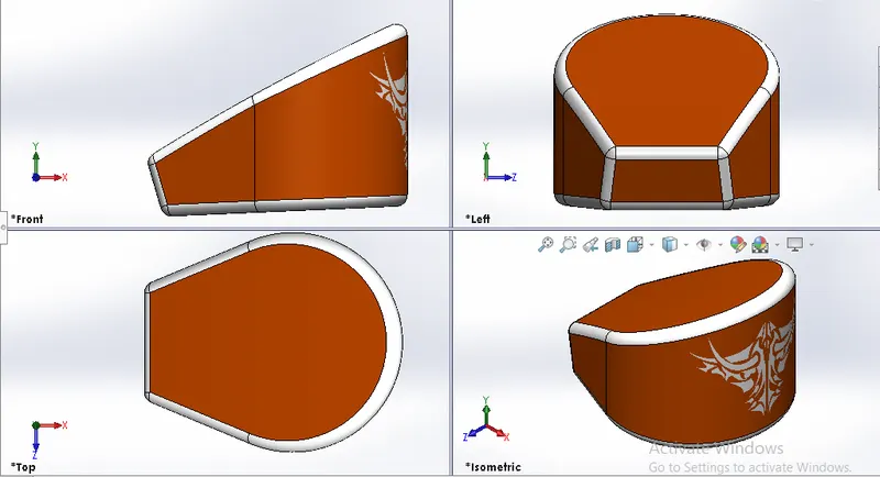
Fig 6. Different views of oil tank.
Features used to oil tank:
- Sketch- The sketch is a two-dimensional representation of the model. there are different sketch options in solidworks like line, arc, circle, rectangle, spline, these are known as entities.
- Extrude Boss- Extrude boss is a option used to convert 2D sketch to 3D model.
- Combine- Combine is the feature used to manually combine two bodies into one body.
- Fillet- Fillet/Round creates the rounded internal or external face of the part.
- Shell- The shell feature used to create hollow body within a body which determines wall thickness.
- Appearance- Improves the asthetic feature in a model.
Design Methadology,
- Open solidworks > New Part > start modeling.
- Top plane > Edit sketch > Sketch > Extrude upto 170mm.
- Front plane > Sketch > Extrude Through all.
- Combine > Select bodies to combine > Operation type ; Common.
- Fillet all corners by R10 mm
- Shell with wwall thickness of 3mm.
- Apperance goto Apperance > Painted > Car > siena.
6. Chain.
Chain is made up of steel and it is used to transmit the power from engine to rear wheel, In this chain sprocket plays a major role in transmitting power.
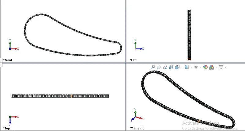
Fig 7. Different views of chain.
Features used to create oil tank:
- Sketch- The sketch is a two-dimensional representation of the model. there are different sketch options in solidworks like line, arc, circle, rectangle, spline, these are known as entities.
- Trim entities- Trim is a type of feature having two options either trim or Extend, amonst them most used command is power trim.
- Fillet- Fillet/Round creates the rounded internal or external face of the part.
- Block- We can create the blocks,save, edit and insert the blocks in our sketch to reduce the modeling time.
- Extrude Boss- Extrude boss is a option used to convert 2D sketch to 3D model.
- Patterns- Pattern is a great feature helps in repeating the sketch or a feature in a axis (i.e. Linear pattern), in circular shape (i.e.Circular pattern) , in 3D curve (i.e. Curve Driven pattern).
- Appearance- Improves the asthetic feature in a model.
Design Methadology,
- Open solidworks > New Part > start modeling.
- Rename the planes i) Front plane > Mid plane chain ii) Top plane > Centre plane chain iii) Right plane > Front plane chain.
- Mid plane > Edit sketch > Sketch > make through way sketch such as chain links > select each link > Right click > Make block > Save in directory.
- Goto sketch > insert block and extrude pins and links accordingly > Exit sketch
- Features > Pattern > Curve driven pattern > Select feature path, No of pattern , Spacing and bodies to be pattern.
- mirror the pattern with respect to mid plane.
7. Pedal.
Pedal is a external part attached to the chassis. the pedal is used to rest the leg on the top of that for rider's comfort.
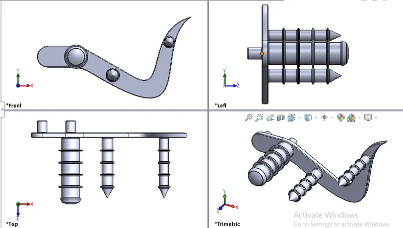
Fig 8. Different views of pedal
Features used to create Pedal:
- Sketch- The sketch is a two-dimensional representation of the model. there are different sketch options in solidworks like line, arc, circle, rectangle, spline, these are known as entities.
- Extrude Boss- Extrude boss is a option used to convert 2D sketch to 3D model.
- Fillet- Fillet/Round creates the rounded internal or external face of the part.
- Patterns- Pattern is a great feature helps in repeating the sketch or a feature in a axis (i.e. Linear pattern), in circular shape (i.e.Circular pattern) , in 3D curve (i.e. Curve Driven pattern).
- Dome- Dome fature is used to create dome on the face with having options such as distane and at which direction dome feature can be accessed.
- chamfer- Chamfer is used to cut or corner the edges, having options such as distance - distance and distance angle chamfer.
- Appearance- Improves the asthetic feature in a model.
Design Methadology,
- Open solidworks > New Part > start modeling.
- Front plane > Edit sketch > sketch drawing > Extrude upto 8mm.
- Sketch on model face > revolve sketch of height 100mm and Ø18mm.
- Extrude boss another two feature having cone at their ends formed by Asymmetric chamfer of dir 1. 16mm and dir 2. 9mm.
- create pattern sketch.
8. Front Wheel.
Wheel is a circular block made of steel or alloy covered by rubber material which supports vehicle to move.
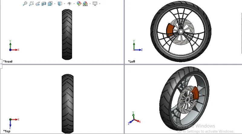
Fig 9. Different views of Front wheel
Features used to create Front wheel:
- Sketch- The sketch is a two-dimensional representation of the model. there are different sketch options in solidworks like line, arc, circle, rectangle, spline, these are known as entities.
- Revolve- To create a revolve feature , create sketch contains one or more profile and a centerline, line, edge to use as the axis around which the feature revolve can bbe used.
- Revolve cut- Used to remove material from the body radially through axis.
- Extrude Boss- Extrude boss is a option used to convert 2D sketch to 3D model.
- Fillet- Fillet/Round creates the rounded internal or external face of the part.
- Patterns- Pattern is a great feature helps in repeating the sketch or a feature in a axis (i.e. Linear pattern), in circular shape (i.e.Circular pattern) , in 3D curve (i.e. Curve Driven pattern).
- chamfer- Chamfer is used to cut or corner the edges, having options such as distance - distance and distance angle chamfer.
- Appearance- Improves the asthetic feature in a model.
Design Methadology,
- Open solidworks > New Part > start modeling.
- Front plane > edit sketch > sketck for rim and wheel hub of Ø660mm.
- Features > Revolve > Rim is modeled.
- Right plane > Edit sketch > Create web and disc for front wheel using features such as Boss extrude, Extrude cut, Revolve cut, circular pattern ,Combine.
- Above that create a disc with cut features in it.
- create wheel tyre and make appearance as rubber material for tyre and chromium for wheel rim and disc.
9. Rear Wheel.
Wheel is a circular block made of steel or alloy covered by rubber material which supports vehicle to move.This wheel facilitates sprocket option has drive system.
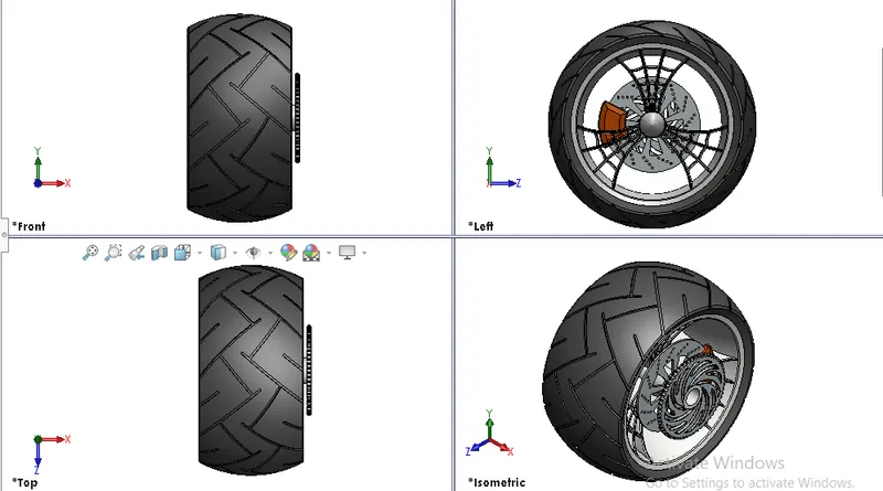
Fig 10. Different views of Rear wheel
Features used to create rear wheel:
- Sketch- The sketch is a two-dimensional representation of the model. there are different sketch options in solidworks like line, arc, circle, rectangle, spline, these are known as entities.
- Revolve- To create a revolve feature , create sketch contains one or more profile and a centerline, line, edge to use as the axis around which the feature revolve can bbe used.
- Revolve cut- Used to remove material from the body radially through axis.
- Extrude Boss- Extrude boss is a option used to convert 2D sketch to 3D model.
- Fillet- Fillet/Round creates the rounded internal or external face of the part.
- Patterns- Pattern is a great feature helps in repeating the sketch or a feature in a axis (i.e. Linear pattern), in circular shape (i.e.Circular pattern) , in 3D curve (i.e. Curve Driven pattern).
- chamfer- Chamfer is used to cut or corner the edges, having options such as distance - distance and distance angle chamfer.
- Appearance- Improves the asthetic feature in a model.
Design Methadology,
- Open solidworks > New Part > start modeling.
- Front plane > edit sketch > sketck for rim and wheel hub of Ø660mm.
- Features > Revolve > Rim is modeled.
- Right plane > Edit sketch > Create web and disc for front wheel using features such as Boss extrude, Extrude cut, Revolve cut, circular pattern ,Combine.
- Above that create a disc with cut features in it.
- Additional Chain sprocket to be created to this model.
- create wheel tyre and make appearance as rubber material for tyre and chromium for wheel rim and disc.
10. Front fork.
Most motorcycles today use telescopic fork for the front suspension. The forks can be most easily understood as large hydaraulic shock absorbers with internall coil springs. They allow the front wheel to react to imperfection in the road and smooth travel.
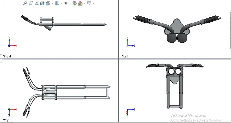
Fig 11. 3 different views along with one perspective view.
Features used to create Front fork:
- Sketch- The sketch is a two-dimensional representation of the model. there are different sketch options in solidworks like line, arc, circle, rectangle, spline, these are known as entities.
- Revolve- To create a revolve feature , create sketch contains one or more profile and a centerline, line, edge to use as the axis around which the feature revolve can bbe used.
- Revolve cut- Used to remove material from the body radially through axis.
- Extrude Boss- Extrude boss is a option used to convert 2D sketch to 3D model.
- Move/Copy body- This feature facilitates to move component.
- Projected curve- To create curve with respect to two planes.
- Sweep- This feature is used to create shape form 2d sketch to 3d by following path.
- Fillet- Fillet/Round creates the rounded internal or external face of the part.
- chamfer- Chamfer is used to cut or corner the edges, having options such as distance - distance and distance angle chamfer.
- Appearance- Improves the asthetic feature in a model.
Design Methadology,
- Open solidworks > New Part > start modeling.
- Front plane > Edit sketch > Sketch for right fork > Exit sketch > Revolve sketch about its axis.
- Create top cover for headlight by using boss extrude feature.
- Create Headlight sketch in front plane > Revolve around axis > Use extrude cut to create focus light feature.
- Use move/copy feature to place right end headlight at required position.
- Features > Mirror > Mirror right fork with respect to top plane.
- give fillets and chamfer at required edges.
- appearance > Lights >Area lights to headlight.
- appearance > Rubber > Glossy rubber to handles.
11. Chassis.
Chassis is foundation for any automobile upon which every parts are being assembled. Here parts such as engine, fork, wheels, fender, gas tank and any more are assembled over chassis to form American chopper.
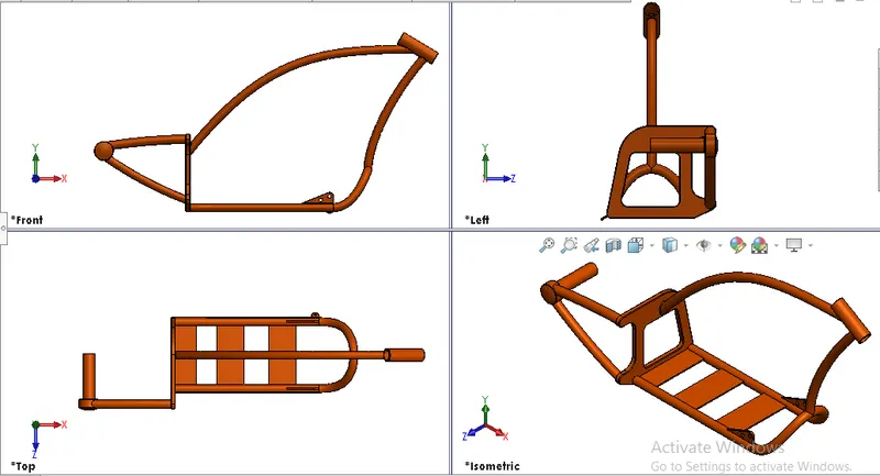
Fig 12. Different views of chassis
Features used to create Front fork:
- Sketch
- Offset
- convert entity
- Project curve
- Trim
- plane
- sweep
- Split
- Revolve
- Cut extrude
- Fillet
- Combine
- Appearance.
12. Engine.
Engine is the heart of an automobile hepls to produce power by combustion strokes made by the piston.
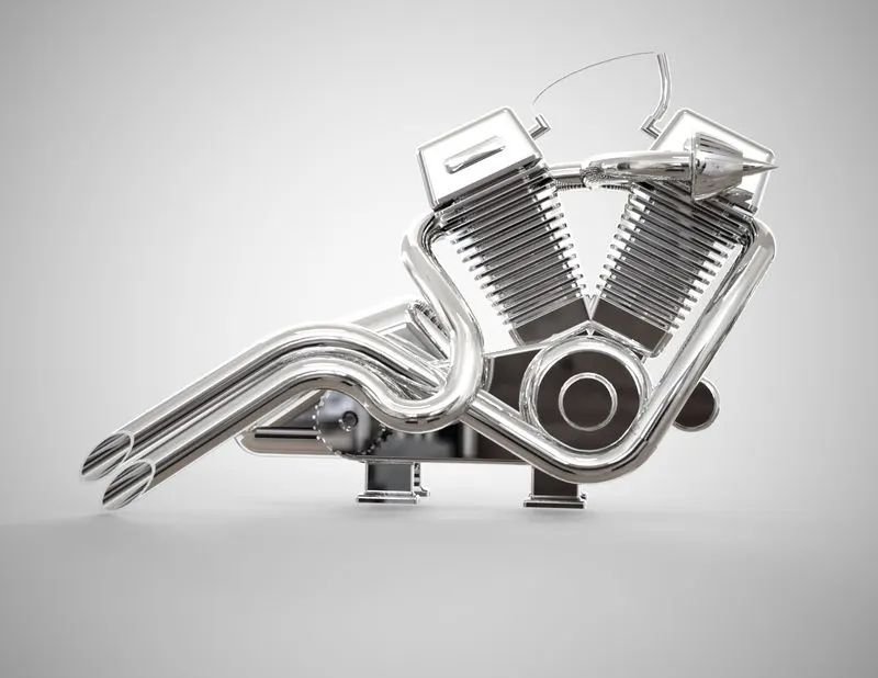
Fig 13. Rendered image of Engine.
Features used to create Front fork:
- Sketch
- Offset
- convert entity
- Dome
- Trim
- plane
- sweep
- Boss extrude
- project curve
- composite curve
- Revolve
- Cut extrude
- Fillet.
- Appearance.
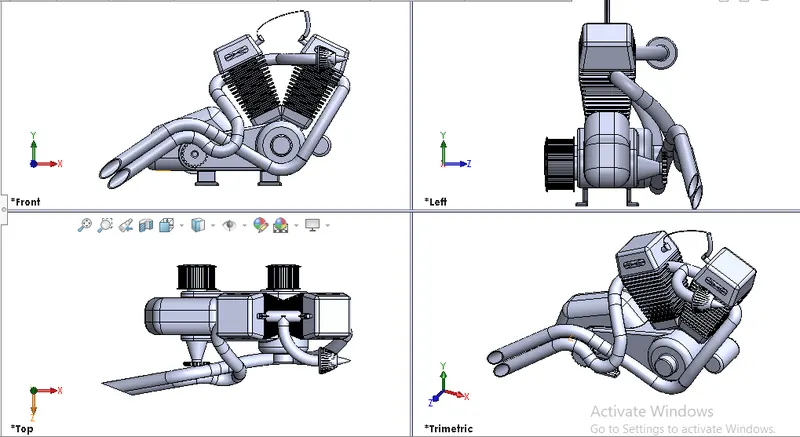
Fig 14. Different views of Engine.
13. Gas Tank
Gas tank is used to store the fuel which helps to drive engine.
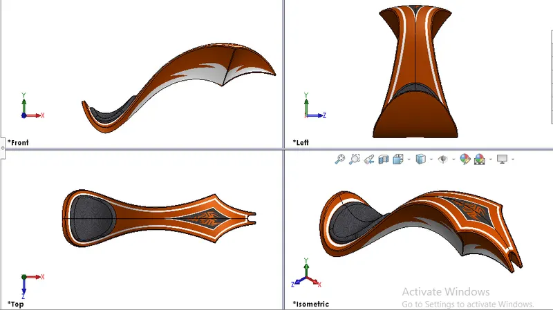
Fig 15. different views of gas tank.
Features used to create Front fork:
- Sketch
- Offset
- convert entity
- Trim
- sweep surface
- loft surface
- fill surface
- surface trim
- knit surface
- Boss extrude
- project curve
- Swept cut.
- Fillet.
- Appearance.
- Loft surface; this feature creates surfaces by multiple 3d curves or existing edges creating a smooth tangency between selected curves.
- Sweep surfaces; Surfaces are generated from section curve positioned along path.
- filled Surface; This feature constructs a surface patch with any number of sides within a boundary defined by existing model edges, sketches, or curves including composite curves.
- Surface trim; This feature helps to cut away material from surface and provides two modes.
- Surface knit;It is used to knit two edges of surface created.
IV. Assembly of the chopper.
In Assembly of the chopper parts are being assembled in assembly section of solidworks Commands used are,
- Insert part
- add mates
- Advanced mates. etc
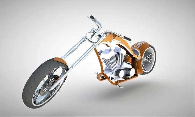
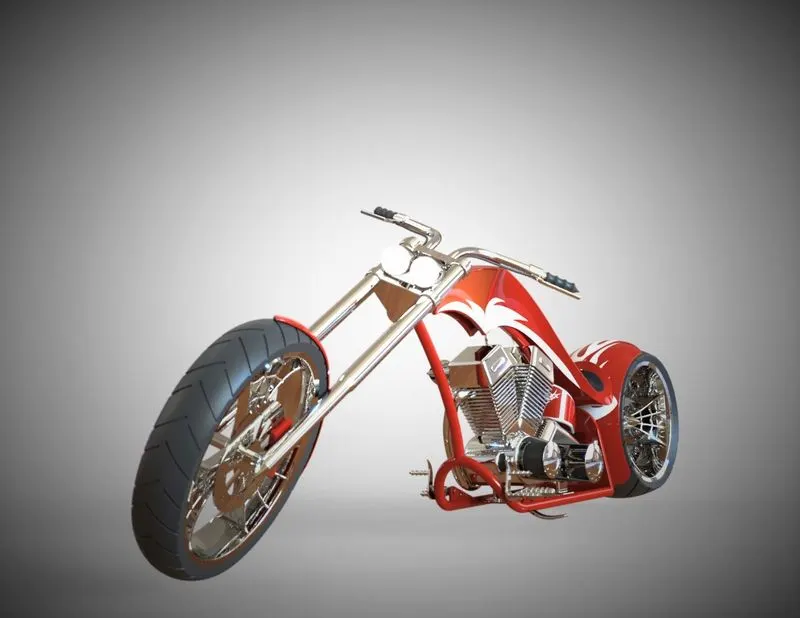
Fig 16. Assembled model 'American chopper'.
V. Rendering
Rendering feature creates photo realistic model with additional faetures such as
- Environments,
- Decals,
- Lights ,
- Perspective view,
- Camera view,
- Solidworks Visualize
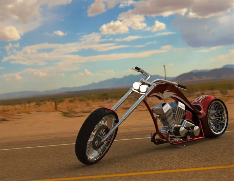
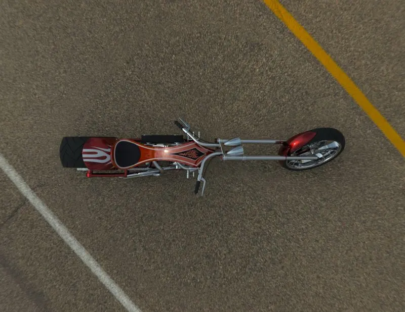
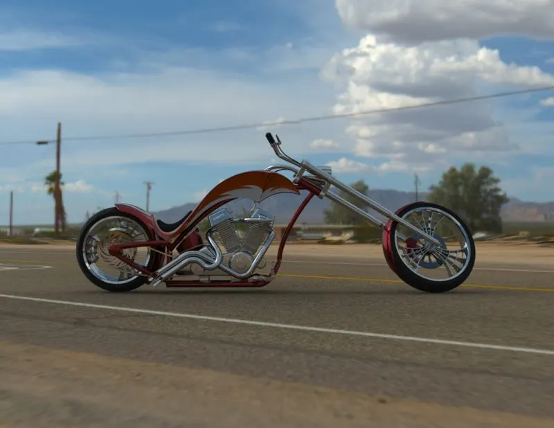
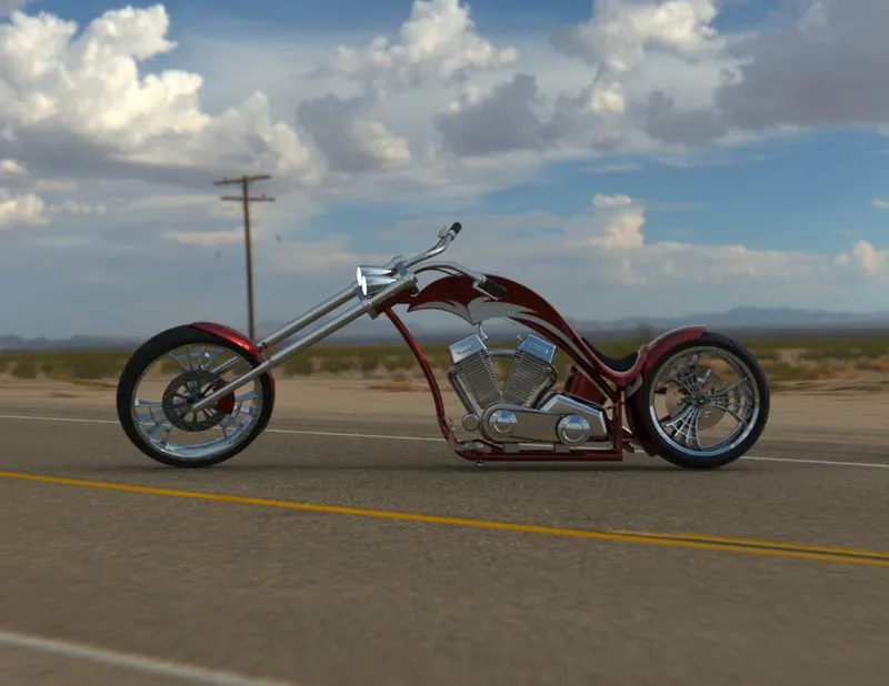
Fig 17. Rendered model
Different views of American chopper.
1. Left view
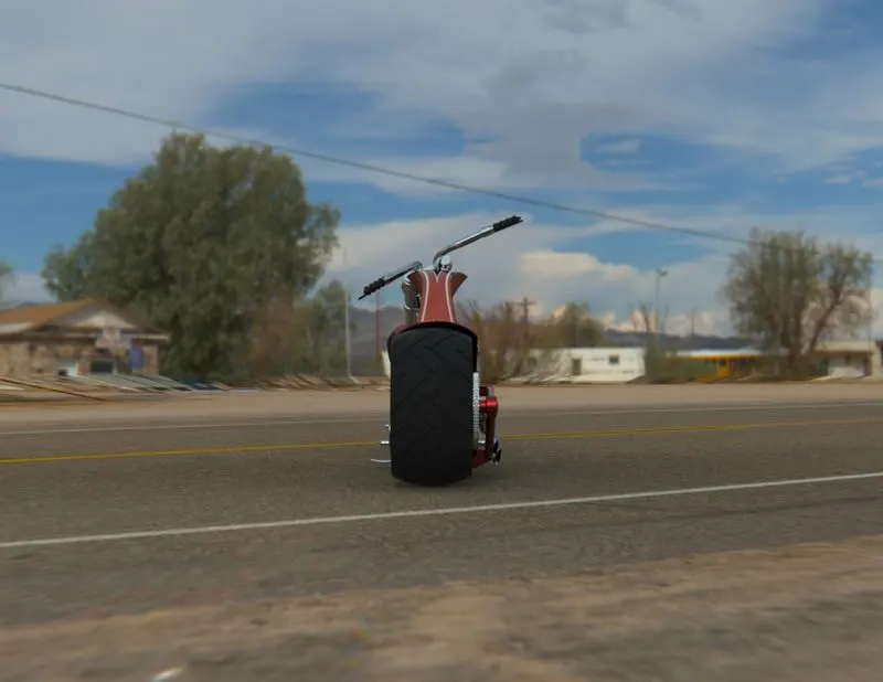
2. Right view
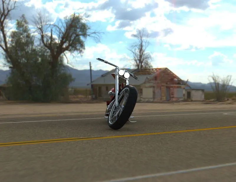
3. Top View
4. Front view
5) Back view.
VI) Conclusion.
- The parts of Chopper are sketched and modelled in the solidworks.
- The parts are inserted into the assembly environment and by applying the mates , chopper is assembled.
- The realistic image was rendered using 'Photoview 360 & Solidworks visualize.'
- I conclude this project is drawn according to the dimensions provided.