Photo Realistic Rendering
MODELLING, ASSEMBLY AND RENDERING OF AMERICAN CHOPPER
OBJECTIVE: The objective of the project is to model the individual parts of an American Chopper and then assemble it using Solidworks. The final assembly will then be rendered using Solidworks Visualize.
INTRODUCTION: The present project to develop an American chopper using Solidworks requires convenient designing of each individual part in the Solidworks environment. The parts which are to be modelled are as follows:
- Transmission Belt
- Kickstand
- Front Fender
- Rear Fender
- Chain
- Oil Tank
- Pedal
- Front Wheel
- Rear Wheel
- Front Fork
- Chassis
- Engine
- Gas Tank
All of these models are design with respect to sketch constraints and is made sure that every sketch profile is fully defined. The next step to consolidate the models, they are to assemble in the Solidworks environment with due considerations given to the mates in order to facilitate further approach. The final assembly is then first rendered in the Photoview 360 render workbench where all the necessary decals, camera and lights etc. are added. This rendered assembly is then imported to the Solidworks Visualize to finally render with a suitable environment and appearances.
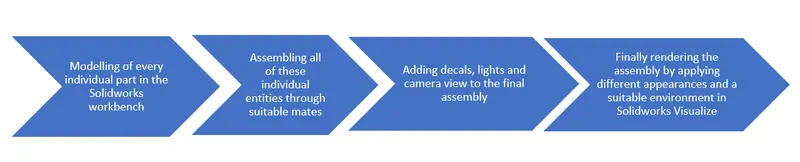
DESIGN METHODOLOGY: The approach to the project is in a subsequent manner where initiating from the sketching till rendering the assembly is conveniently performed. The flow chart resembles the sequence in which the process follows.
DESCRIPTION: The following parts which were listed above required various features and tools to fully define and construct the overall component. The sketches were ensured to be fully defined and the entities, in the end, were applied fillets to facilitate designing by reducing stress across the profile. The respective parts were designed along with the following steps:
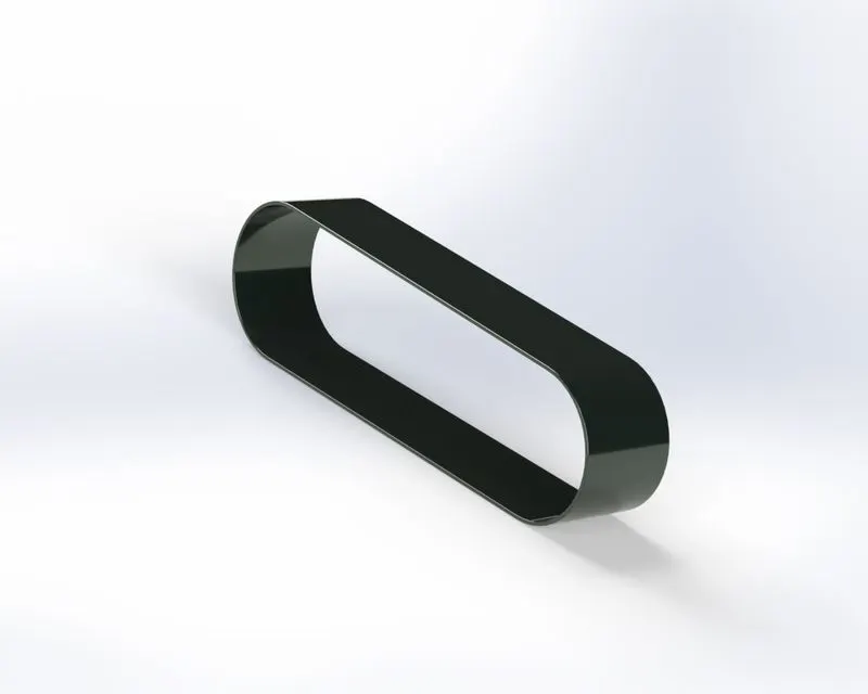
1. Transmission Belt: The Transmission Belt made here is to transmit the motion between the two pulleys.
- The sketch profile for the transmission belt was made using the line command and then applying some tangency relations made it fully defined.
- The sketch was then offset at a certain distance
- The final profile was extruded to get the component.
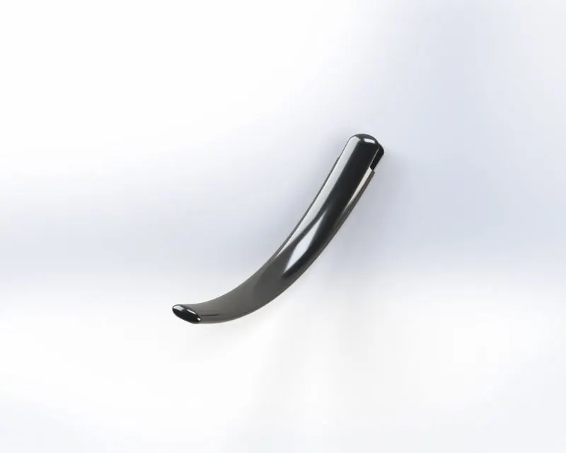
2. Kickstand: The kickstand is made to lean the chopper against things.
- The sketch Profile was made with the line as well as spline commands.
- The profile was so adjusted to accommodate a plane at one end in order to create another sketch to sweep through the former profile.
- To have the aesthetic look of a kickstand it is extruded cut from one end
- The profile is further supported by an in-between extruded boss to support the extruded cut area.
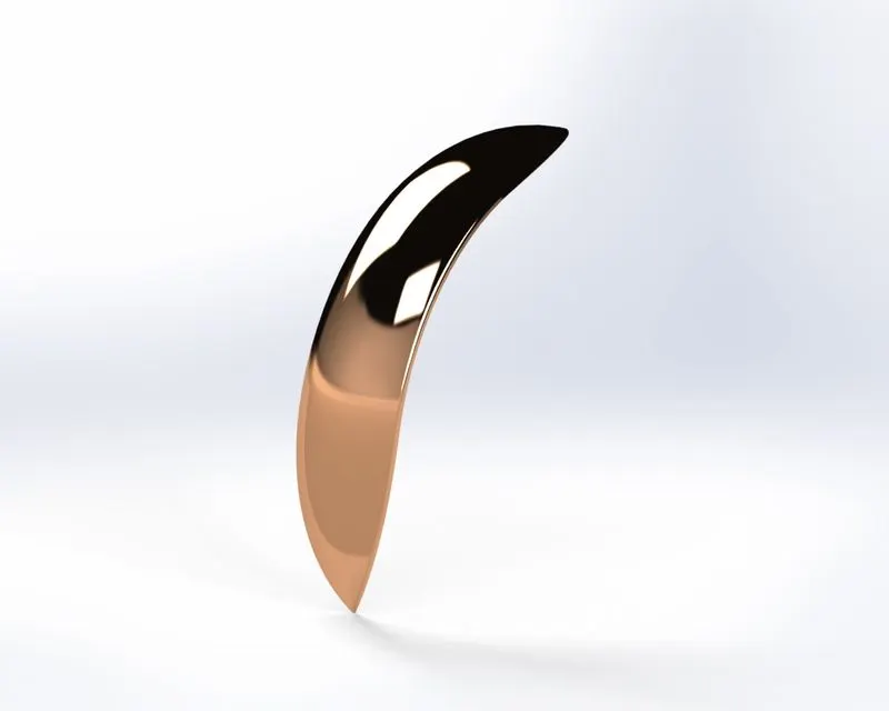
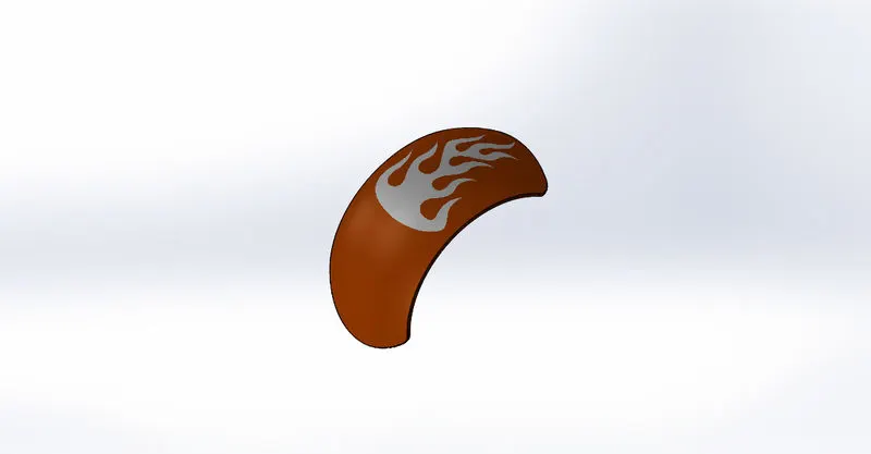
3. Front Fender: Fenders are frame over a wheel to prevent the foreign particles to enter which strikes it while the tyre rotates.
- The first profile created using a spline command is rotated using a revolve feature at a certain angle.
- The other two profiles created are split along the former profile from the respective ends using the split feature.
- To give the appearance the fender is given fillets as well as a Siena paint.
4.Rear Fender: Similar to the front fender the profile is first created and then revolved at a certain angle and then split. The only other feature is applied is a shell to the entire component.
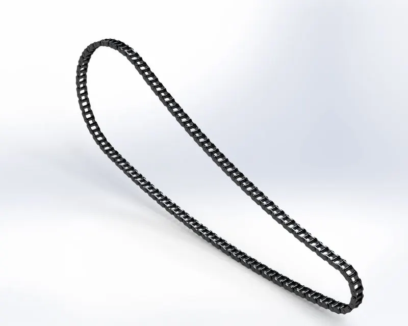
5. Chain: The chain is also used to run over the pulleys to transmit power to propel the body.
- The chain profile is first created along which all the pins and the chainplates will run through the circumference of the profile.
- The profile is divided into four sections to have a smooth transition around each section.
- The plates and pins are sketched alongside which are then extruded using extrude feature and is successively extruded to get the first two links.
- Fillets are respectively added to both the plates and pins.
- This link is then applied to a curve driven pattern in the profile section by section.
- This entire pattern is then mirrored along the midplane.
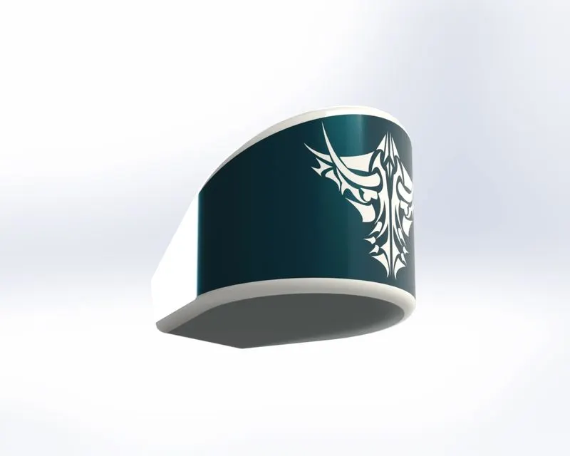
6. Oil tank: The oil tank is used to store the liquid inside them.
- There are two sketch profiles are created using the line command and fillets are added in the sketcher workbench itself.
- These two profiles are then extruded which is then combined using a combine feature to get the profile of an oil tank.
- To give the appearance to the fillets which are added to the boundary is given separately to the fillets excluding the faces.
- The faces are then given a Siena appearance.
- The entire solid body is then emptied using a shell feature.
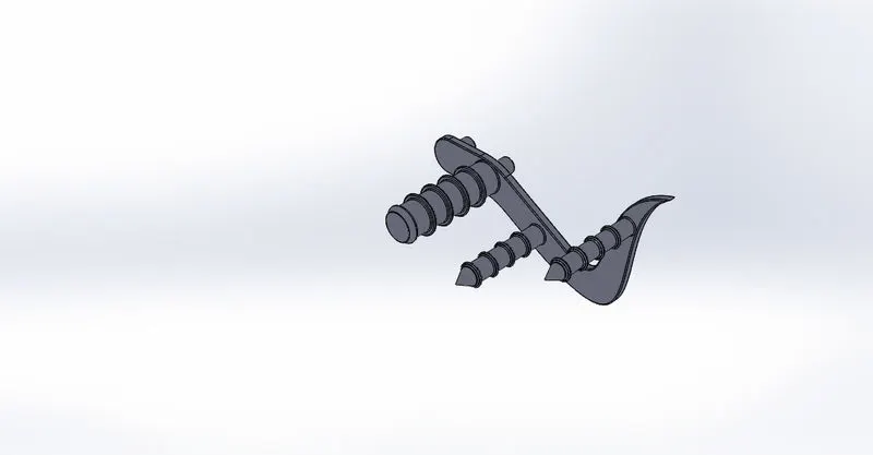
7. Pedal: Pedal is the support that is present to step one's foot over it to support while riding a bike.
- In pedal, the base profile is created using line and spline commands, and a circle command is used to protrude it out for support.
- The sketch created is extruded separately such that other extruded profiles are used for fixing within the assembly.
- The other sketch created is revolved using revolve feature and a dome is added to one end using the dome feature.
- More two profiles are extruded on the same side and chamfered using the Chamfer command at one end.
- In order to generate a linear pattern along with these extruded and a revolved profile, another small extrusion is created and patterned for 4 instances.
- Finally, fillets using the Fillet feature is added.
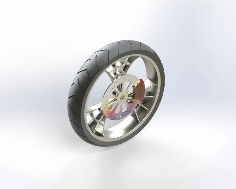
8. Front wheel: In order to run over the surface over which a bike rides a wheel is made having suitable material to withstand the impact. The front-wheel and rear-wheel both have four solid bodies which are the rim, calliper, rotor and tyre.
- The wheel has a spider-webbed rim where firstly the profile is revolved entirely to get the rim circular section.
- Next, the spider-webbed design is made using the spline and line commands where the sections are then offset and trimmed to firstly get extruded separately and then get extruded cut to form the web structure.
- These rims are then patterned for 3 instances along the circular section. using the Circular pattern feature.
- At this stage, some fillets are applied to the body by firstly combining them using a Combine feature.
- Next, a rotor is made by first making a circle and then extruding it at a certain distance. Further, a circular profile is patterned along the front side linearly and this entire profile is extruded cut.
- This extruded cut is then patterned along the circumference using a circular pattern feature.
- Another profile is created and then applied a circular pattern after getting extruded cut. These profiles are created for heat dissipation.
- To have the common centre to get mate a cut through all is created from the overall body.
- After this, a calliper is made using circle, line and trim commands. This profile is then extruded and applied fillets.
- Lastly, the tyre profile is created and then rotated along the circular section, along with in order to have gaps over the surface of the tyre a profile of a centred rectangle is created over it which is then applied fillets and is patterned circularly over the entire tyre using Circular pattern feature.
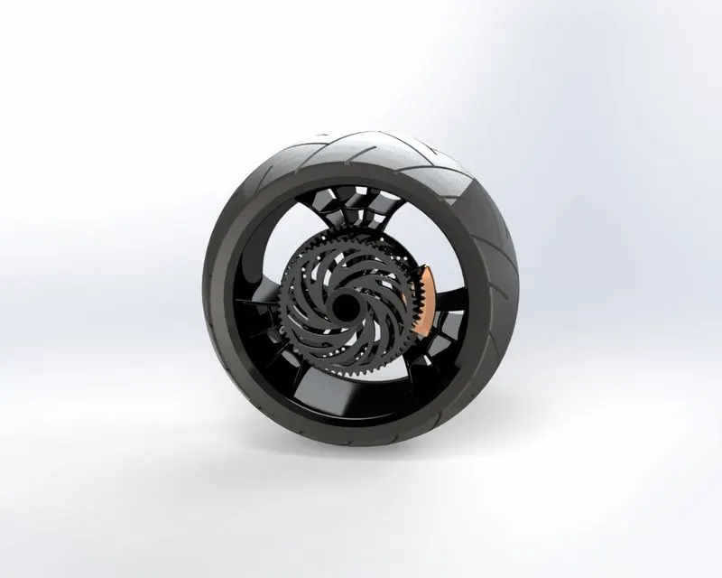
9. Rear wheel: The building of a rear-wheel is similar to that of a front wheel, having only an extra body added i.e. sprocket.
- After following the same process up till calliper, The sprocket is created by first creating a circular section.
- This section is extruded at a certain distance with an offset from the plane.
- To have gear-like teeth over its periphery a small section is created and then extruded.
- This section is then applied fillets using a fillet feature and then patterned over the body using a circular pattern feature.
- The other two profiles are created over the face of this sprocket which is then cut using the extrude-cut feature.
- These profiles are then applied fillets and patterned over the face using a circular pattern feature.
- After this, the tyre follows the same process as that in a front wheel.
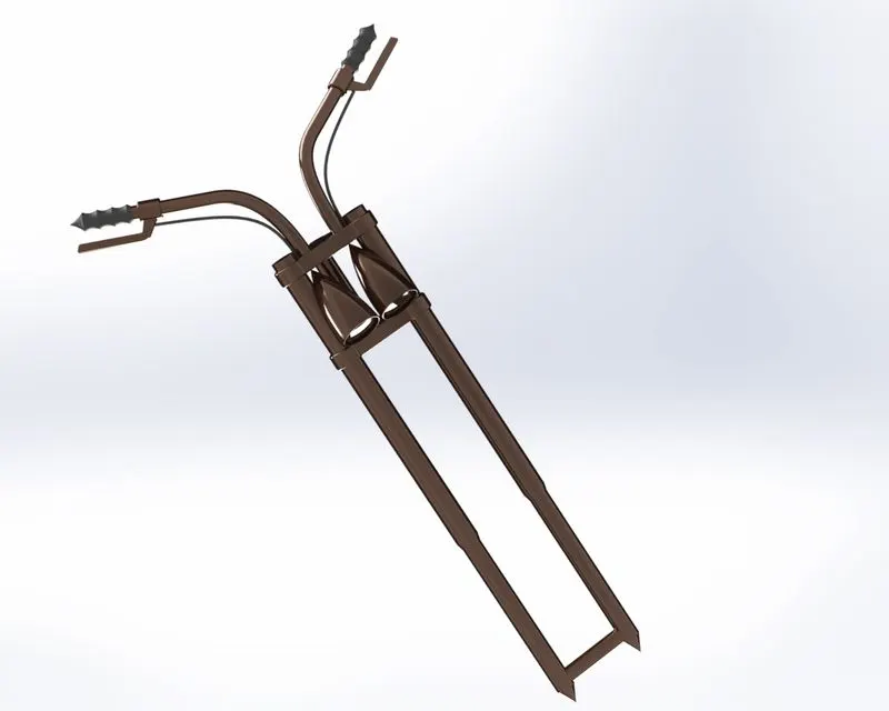
10. Front Fork: The front fork is used in a bike to manoeuvre it as per a driver's requirement.
- Here the fork profile is created in such a manner since most of its parts are mirrored along its midplane. Therefore its first end is created using line commands and then revolved along its axis.
- The supporting feature over this profile is made to hold the handles where it extruded using the boss-extrude feature. Some of the profiles are then applied fillets and then this profile is linearly patterned along the first end rod with an added instance using a linear pattern feature.
- The middle rod is created using a circle command and then extruded along the midplane using a boss-extrude feature.
- Now headlamp is created using a spline and line command and then this profile is revolved using a revolve feature. On the inside of this headlamp, a dome is created so that it appears as reflecting the light and is made using the dome feature.
- The fillets are applied using the fillet feature to the headlamp.
- To make a handle for the front fork a composite curve is made using the Composite curve feature where initially two profiles of spline are made which in turn are selected to generate the composite curve pattern for the handle.
- At one end of this curve, a circular profile is created in order to sweep it through the handle using the Sweep feature.
- To generate an accelerator firstly a plane is made on which a profile of accelerator is made which can be revolved around its end using a revolved feature.
- To create a brake another plain is created on which the profile of the brake is created and is extruded using the boss-extrude feature.
- The brake lining is generated using both composite curve and sweep feature where firstly two curves are created and then a composite curve is generated and then finally sweeping a profile through it by creating a one at its end.
- Finally, the headlamp, handle, brake, brake lining, rod end and supports are mirrored along the midplane to get the complete profile of the front fork.
- All of these bodies are then combined to one using the combine feature.
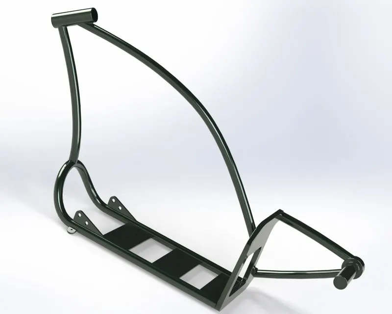
11. Chassis: It is the frame on which the body parts are mounted.
- In order to have an exact profile of the chassis, a blueprint chopper image is required which is added using the sketch picture command in sketch tools.
- Now two curve profiles are created, to generate a composite curve by using a composite curve feature. This profile mirror is generated along the mid-plane using a mirror feature.
- The vertical profiles created and extruded using the boss-extrude feature. A cut profile is generated in the centre using a cut-extrude feature. Furthermore, fillets and chamfer are added to this profile.
- Furthermore, a plane is created offset to the midplane where profiles for a sweep and extrude are made using the sweep and boss-extrude feature. A dome is created using a dome feature command at one end
- To make the upper section of the chassis two planes are created where one is offset to the right plane and another to the bottom plane. Here on this offset plane profiles to create a sweep feature are made using circle and spline commands and completed using a sweep feature.
- These two swept features are intersected by a common entity which is made using a revolve feature.
- All these entities intersect with each other where it is needed to be split and then made into one which is done by using a Split and Combine feature. After this fillets are added using a fillet feature.
- In the bottom, to clamp with other components a profile is made and then extruded using a boss-extrude feature. This profile has some part of it inside the bottom section which is split using a split feature. Finally, this profile is mirrored along the midplane using the mirror feature.
- In the end, all the necessary fillets are added using a fillet feature and combined using the combine command.
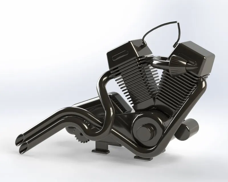
12. Engine: An engine is something that will power our chopper.
- In order to have an exact profile of an engine, a blueprint chopper image is required which is added using the sketch picture command in sketch tools.
- To create the motor section the sketch profile is created using circle and line commands and then added relations of tangency. This sketch profile is extruded 3 times subsequently by selecting different sections of the profile every time using a boss-extrude feature.
- The transmission section is also created by first creating the profile and then using the boss-extrude feature. This section is then given fillets using the fillet feature.
- In order to house the transmission belt, two pulley profiles are made. Firstly a plane is made offset to the right plane and two sections for pulley is created using line command and then revolved using a revolve feature.
- To have teeth on this circular section a boss-extrude is created which is then patterned using the circular pattern for 40 instances on both the pulleys. Along with this, a dome is created using a dome feature. To get a much better profile a sketch is created which is extrude cut at offset distance in the reverse sense at both the pulleys.
- The section is then chamfered and added fillets using the chamfer and fillets command respectively.
- After this, a reference line is created to create a plane for making the cylinder profile. After this, a sketch profile is created on this plane which is extruded with a draft angle using the boss-extrude feature. A similar profile is created above it using the boss-extrude feature and is then applied with chamfer over its vertical faces using the chamfer command.
- To house this cylinder over the motor section a sketch is created using line command and then boss-extruded using the boss-extrude feature.
- A cut profile is created on the bottom section of the cylinder profile which is then linearly patterned using linear pattern feature for 14 instances with certain spacing. This entire cylinder profile is then applied fillets using the fillet feature.
- Since some part of the cylinder might enter the motor section, therefore it is needed to be split using the split feature command. This cylinder profile is mirrored using the mirror feature.
- In between these two cylinders, the spark plug profile is created using circle and spline command and swept using sweep feature.
- The base of the engine is needed to be mounted on the chassis, for which four-centred rectangle profiles are created and then extruded using the boss-extrude feature and applied fillets using the fillet feature.
- The sprocket on one side of the motor is created using the boss-extrude feature and then to create a gear like profile over the periphery a cut is created using the cut-extrude feature and the patterned over the periphery using the circular pattern feature using equal spacing.
- To make the exhaust section composite curves are created by using the composite curve feature and then finally sweeping them using the sweep feature. For this different planes are created and reference sketches are created and then finally splitting at the end using the split feature.
- Finally, the bodies are combined using the combine feature.
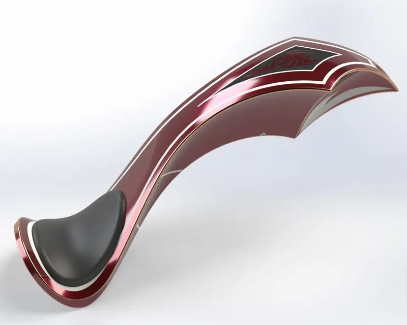
13.Gas Tank: It is the container also called a fuel tank that is used to contain the flammable liquids inside them.
- To have an underlay of a fuel tank, a blueprint chopper image is required which is added using the sketch picture command in sketch tools.
- An offset plane is created to the front plane where a sketch profile is created to make a sweep section of the gas tank using the sweep feature.
- Now another sketch profile is made on the bottom plane such that it is needed to be trimmed using the surface trim command from the upper profile.
- Another plane is created offset to the midplane where two curve profiles are created using the spline command. These two curves are then used to project a curve using the project curve feature. Another sketch is created to complete the curve and make it a closed section after which the surface loft command is used.
- Another offset plane is created to the front plane where two curves are then made to project a curve using the project curve feature. To make a closed feature two more sketch profiles are created using line command and then finally closed using the boundary surface command to get a smoother profile.
- All these profiles created are then mirrored using a mirror command. These surfaces are knit together using the surface-knit command.
- To make the seat split line is created in between the profile by creating the sketch and then extruded using the surface extrude feature. The necessary fillets to the boundary of the seat are added using the fillet feature.
- To clamp this tank with the body the bottom section is closed through halfway using the boundary surface and the surface loft feature and finally knitting them together using the surface-knit command.
- After this, a cut is created along this surface in the bottom section using the cut-sweep command. After this fillets are added using the fillet feature command.
- Finally, the entire body is emptied using the shell command.
ASSEMBLY AND RENDERING USING PHOTOVIEW 360
All these parts created are needed to be assembled suitably through proper mates among parts. the various mates which can be used to accomplish our assembling are coincident, concentric, limit angle, width, angle, parallel, distance, tangent etc.
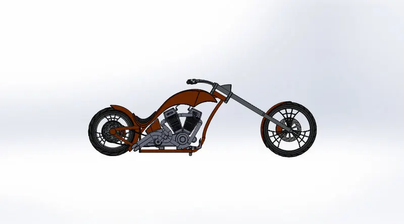
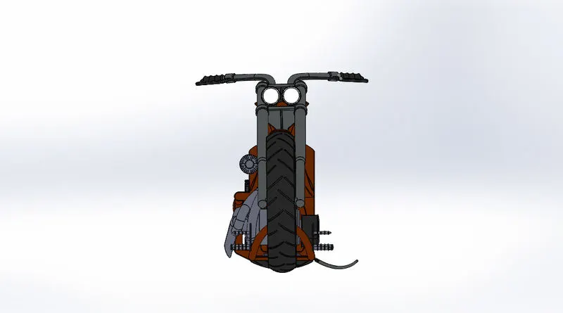
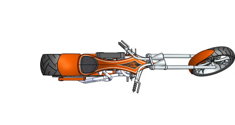
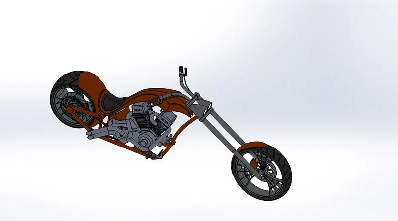
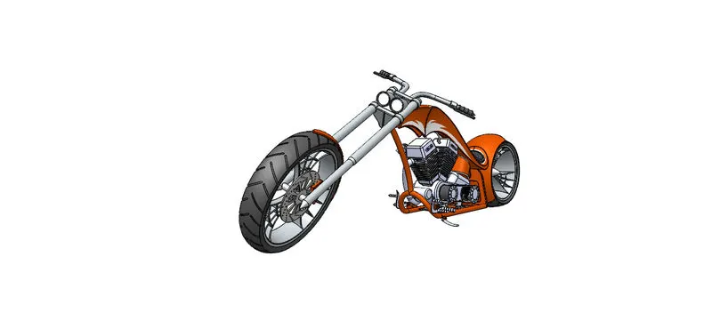
After the assembly of the chopper, one can render the chopper using the photoview 360 where all the necessary decals, camera setup, lights etc. The decals are added to some of the parts of American chopper, in order to have a more aesthetic appearance of the bike. While adding decal, one needs to use it in the alpha channel so that we get a clear background, while mapping one can choose in-between the projection, label, cylindrical, spherical etc. I illumination one has to use the underlying appearance. To add a camera view as well as the lights to the scene one can choose to select the add camera or add lights in the view toolbar where one can setup in accordance with one's perspective.
RENDERING IN SOLIDWORKS VISUALIZE
While rendering the Solidworks visualize one can add the assembly in under appearance perspective where while creating a new project one has to import the assembly and then tweak among various option to finally render the assembly. One can have different appearances for the assembly whereas one can also choose different rendering environment and edit them as per the requirement.
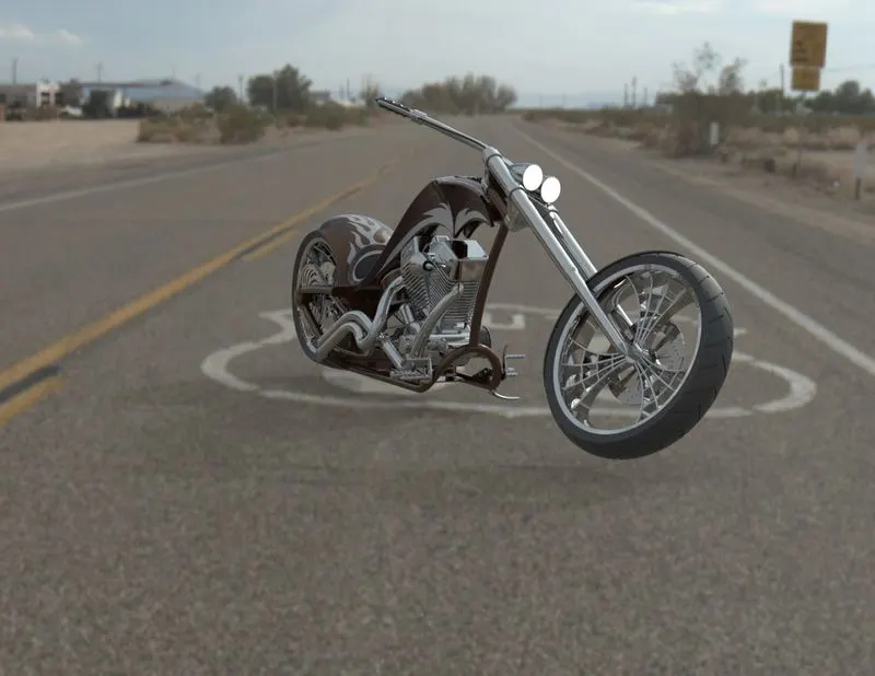
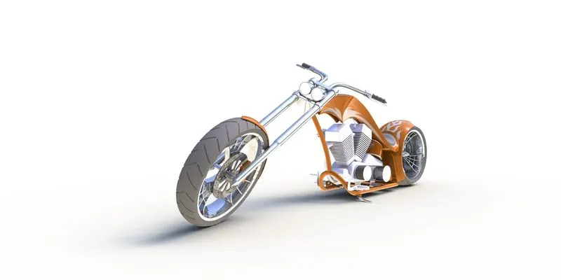
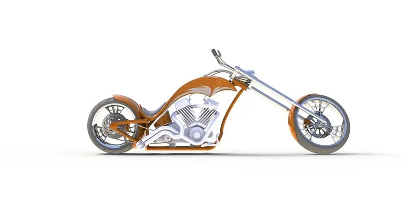
CONCLUSION: Hence the modelling, assembly and rendering of an American Chopper have been done successfully.