Chopper Assembly and Photo Realistic Rendering
Assembly of Chopper Model in Solid Works
Objective:
The main objective of this project is to Assemble the American Chopper Model. Also, to get explore in the solid works software and its workbenches in detail.
Introduction:
The American Chopper Model is one of the ancient and Retro bike model Design. This chopper consists of the following components
- Front fork with Head light
- Gas Tank with decals
- Oil Tank
- Engine
- Chassis
- Kick stand
- Belt drive
- Chain drive
- Foot pedal
- Front and Rear Fender
- Front and Rear Wheel
- Rider Seat
This project is completed by designing the individual components and then assembled together.
Design Methodology:
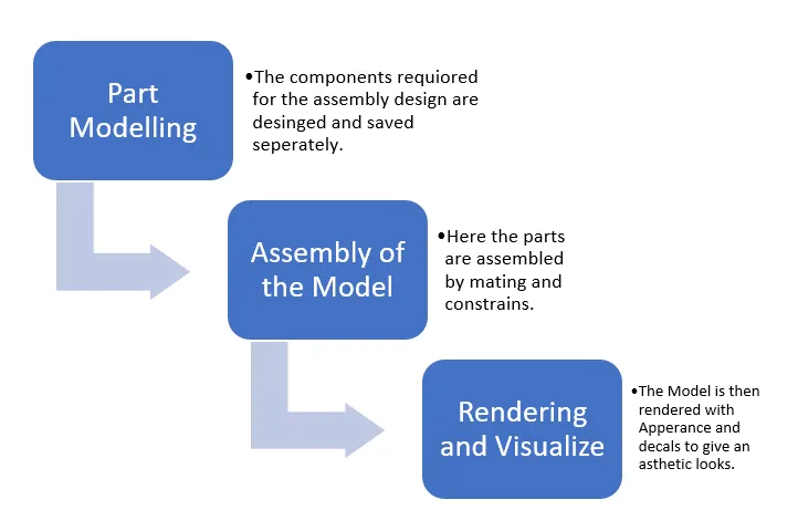
This is one of the Bottom-Up Approach design methodology, where we are used to design and model the parts first and then by inserting all the parts into the assembly workbench.
To get an overview of the design model, we have imported the Chopper model picture into the part modelling workbench.
Modelling has been done by constraining the sketch, so that there won’t be any modification while doing assembly. Also, some of the dimensions were approximate, that is solved in the assembly workbench to get the proper mating and constrains.
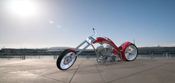
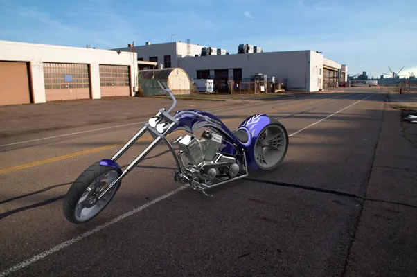
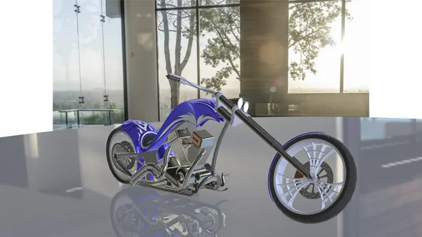
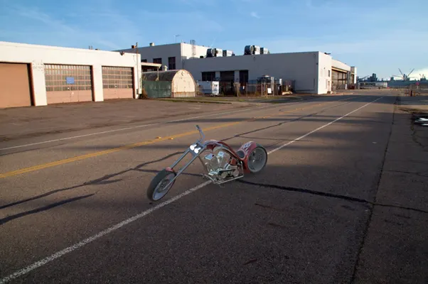
Rendering the parts has been carried out in the final stage of the project. This gives good appearance to the bike and the back ground scenes were added to give aesthetic looks and feel of the Chopper.
Description:
The Features used for the following Part Model Design:
Extrude Boss: This is used to extrude the base sketch or selected sketch contour in one or two direction to create a solid feature.
Revolved Boss: This is used to revolve the base sketch or selected sketch contour around the axis to create a solid feature. The revolving degrees can be controlled here.
Swept Boss: This is used to sweep a closed profile along an open or closed path to create a solid feature.
Boundary Boss: This feature adds the material between profiles in two direction to create a solid feature.
Extruded Cut: This removes the material from the sketched profile in one or two directions. We can also add draft angle while removing the material.
Revolved Cut: This cuts the solid model by revolving the sketched profile around the axis.
Swept cut: This cuts the solid model by sweeping a closed profile along the open or closed path.
Fillet: This is used to remove the sharp edges form the model by creating rounded faces in the internal or external edges.
Chamfer: The chamfer tool creates a beveled feature on selected edges, faces, or a vertex.
Linear Pattern: Pattern features, faces or bodies in one or two linear directions.
Circular Pattern: This is same like linear but the pattern occurs in the circular directions with angle.
Shell: This is used to hollows out a part by leaving the open faces which we are selecting and creating the thin-walled feature on the remaining faces. If we don’t select any of the faces, then it will create a closed hollow model.
Knit Surface: This is used to combine the two or more adjacent, non-intersecting surfaces into a single surface body. The surface must join at an edge.
Combine: Combine two or more single bodies. Also, we can combine the common intersection faces.
Split: Create multiple body from the single body.
Convert Entities: This is used to convert the selected edges or sketch entities into identical entities by projecting them onto the sketch plane or face.
Design of Chassis:
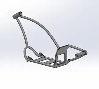
- The chassis is the most important component in the bike. This is like skeleton of the bike, which will carry the main components like Engine, gas tank, Foot pedal, Wheel etc.
- Before stating the design of chassis, the blue print image of chopper is inserted into the part modelling workbench. This gives the Reference stating point for the whole design and dimensions.
- The design was started by curve projection, which converts the 2d sketch into 3d projection curve. Then it is followed by the various feature options like sweep, Mirror, boss extrude, Split, combine, chamfer, fillet, plane creation, dome, cut extrude etc.
Design of Engine:
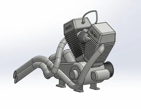
- Engine is like the heart of the bike. Engine itself consists of various components like piston, connecting rod etc. Our aim is to design the overall design of the chopper. So, the engine design is concentrated only on the outer part like fins, drive shaft, exhaust, starter motor, air filter etc.
- Engine design was started from the blueprint image, then it is followed by sketching and boss extrude feature.
- The features used in this design were boss extrude, revolve, circular pattern, fillet, curve projection, dome, cut extrude, chamfer, plane creation, Linear pattern, composite curve, sweep, split, combine.
Design of Gas Tank:
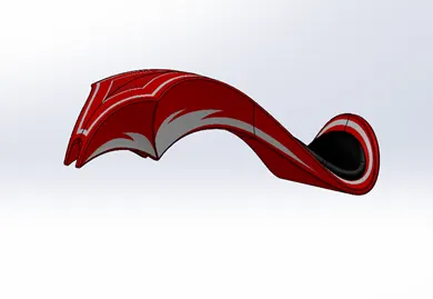
- Design of Gas Tank is done in Surface modelling workbench.
- Gas Tank is used to store the Fuel for the chopper and it also gives the aesthetic look to the bike.
- This can be done by surfacing features like Boundary Fill surface, swept surface, Extrude surface.
- The Rider seat is integrated with the Gas tank itself.
- The Graphics Designs are added in the Gas tank with Appearance and Decals option.
Design of Oil Tank:
- Oil Tank is used to store the Engine oil in the chopper. This oil is used as the Lubricant for the engine which is used to reduce the Friction in the Moving parts.
- This oil Tank Design is done in Part Modelling Workbench. The combine feature, shell and fillet are the options used to design this oil tank.
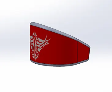
Design of Fender:
Front:
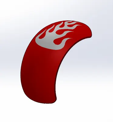
- Fender is used to prevent the engine and its parts from the mud rolling from the tyre.
- The features used for designing Front fender is revolve, shell, fillet and split.
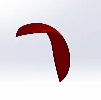
Rear:
- Rear fender is used to prevent the Rider and pillion to from the mud rolling from the rear tyre.
- The same above front fender features is used for Rear also.
Front:
Rear:
Design of Wheel:
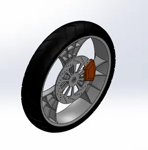
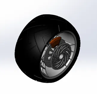
- The wheel design consists of Rim with alloy, tyre, Disc brake and its calliper.
- The three alloy spokes were designed to add strength for the rim and to give looks for the bike.
- The Features used for Wheel design are revolve, circular pattern, extrude, chamfer, fillet, extrude cut etc.
- The Rear wheel tyre is bigger in size when compared to front wheel. This gives extra stability to the bike.
Front:
Rear:
Design of Front Fork:
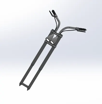
- The Front Fork in the chopper consists of Head light, Handle bar, break Lever and Handel Grip.
- This fork is designed by using Mirror feature. Half of the model is designed and then mirrored.
- The Head light is designed and by adding Light Appearance, which gives the actual look as the light.
- The feature used to design the fork are Revolve, Boss Extrude, fillet, Linear pattern, cut extrude, dome, cut revolve, projection curve, body move, sweep. Combine.
Design of Foot Pedal:
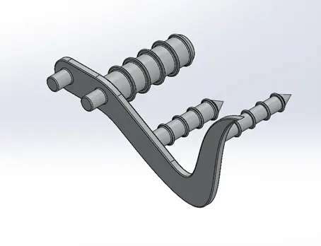
- The Foot Pedal in bike is used to rest the foot and to do some mechanical operations like Break applying, Gear shifting.
- The feature used are Boss extrude, fillet, revolve, dome, Chamfer, Linear pattern etc.
- During the Assembly of the bike the foot pedal in the Left side mirrored using mirror feature in the assembly feature.
Design of Kick Stand:
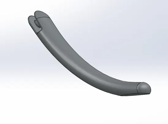
- The Kick Stand is used to keep the bike parked. This stand takes the partial weight of the bike while parking.
- The Kick stand is designed by using spline feature and split line. Split line is used to make the bottom flat in the stand, which give stability to the bike.
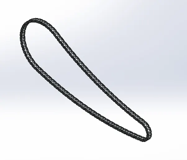
Design of Chain:
- Chain is the Power Transmission component from the gear box to the wheel in the bike.
- The chain is connected to the Sprocket and it is driven by the engine to transmit motion to the wheel.
- The Chain consists Inner Link, Outer link, and the cylindrical pin.
- The feature used to design the chain is Curve driven pattern. There are 4 curves and the chain is patterned along these curves.
Design of Belt:
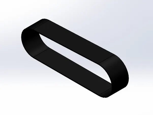
- Belt is also the Power Transmission component.
- The Belt design is done by using Boss Extrude and fillet feature.
Rendering:
- Rendering is the additional feature which gives the actual look and feel of the bike model.
- This is done by adding different materials to the different components like Rubber to the tyre, chrome look to the Engine and chassis.
- These can be done by using Photo view 360 add-ins.
- Solid works Visualize is used for the final rendering with custom background options.
Rendered Images: