PFI full hydro case setup
Aim:
To setup Full Hydrodynamic simulation for Port Fuel Injected (PFI) gasoline engine.
Objective:
1.To setup Full Hydrodynamic simulation.
2.Calculate compression ratio,combustion efficiency,power and torque for the given engine.
Theory:
Port Fuel Injected (PFI):
Port injection sprays the fuel into the intake ports where it mixes with the incoming air. Port injection systems are much cheaper to manufacture. The injectors are not exposed to the high heat and pressure of the combustion chamber and they don’t have to handle high fuel pressures. Port injection systems typically operate in the 30 to 60 PSI range, which is dramatically lower than direct injection systems. Support systems such as fuel pumps are also cheaper, because fuel pressures are lower. Port injection systems spray the fuel on the backside of the intake valve and the fuel has to wait till the valve opens. The fuel sprayed on the backside of the intake valves, also cleans the valves. The injectors are often mounted in the intake manifold runners and the fuel sits in the runners until the intake valve opens and the mixture is pulled into the engine cylinder.
Geometry:
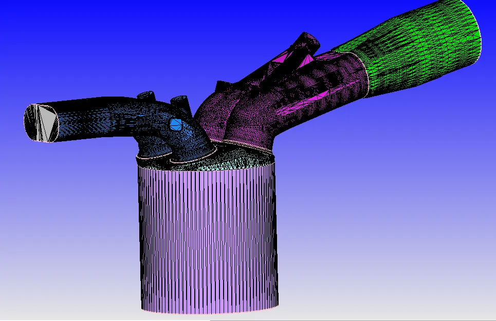
Engine Geometric Parameters:
Bore =0.086 m
Stroke = 0.09 m
Connecting rod length = 0.18 m
RPM = 3000
Materials:
Gas Simulation:
In gas simulation tab, import filr therm.dat which contain species involved in chemical reaction during combustion.
Parcel Simulation:
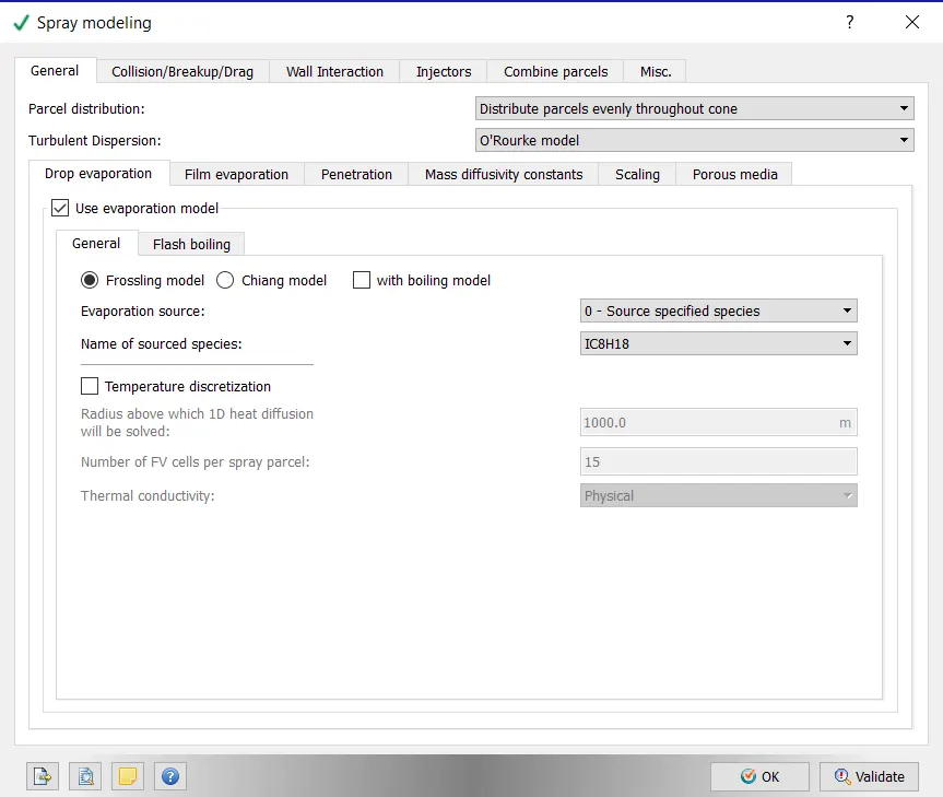
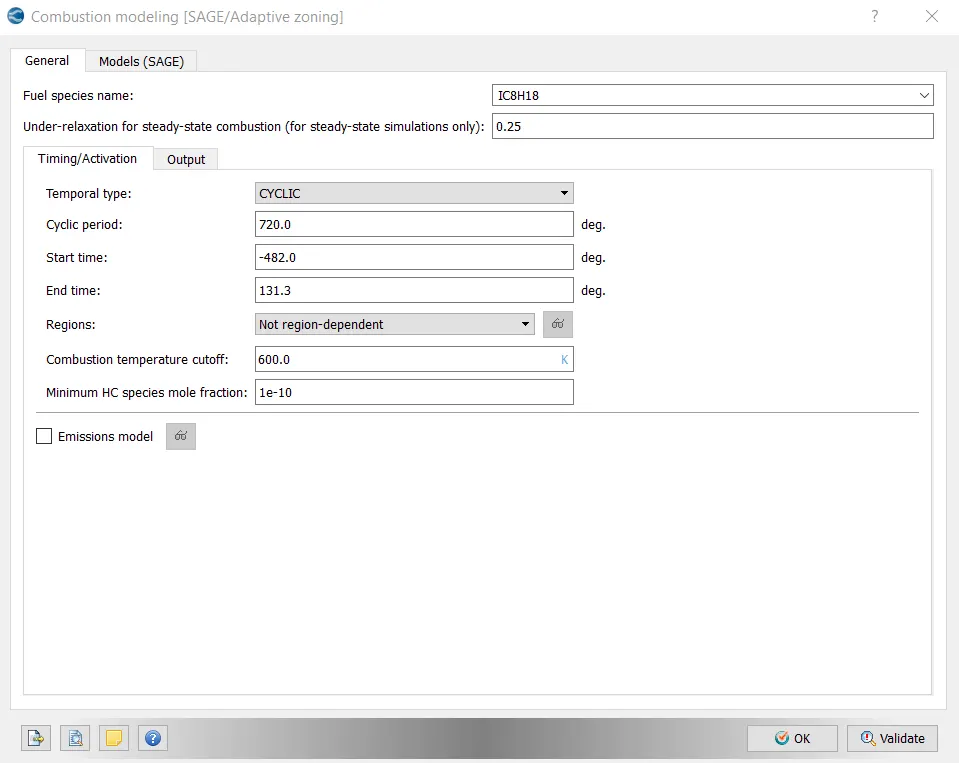
In Parcel simulation tab,select IC8H18 as fuel.Here we are taking Iso octane as fuel as it has properties simillar to gasoline fuel.
Reaction Mechanism:
In Reaction mechanism,import file mech.dat which contains thermodynamic data of species involved in chemical reaction.
Simulation Parameters:
Run Parameters:
Select simulation mode as full hydrodynamic.
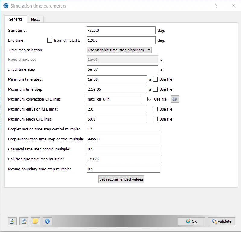
Simulation Time Parameters:
Boundary Conditions:
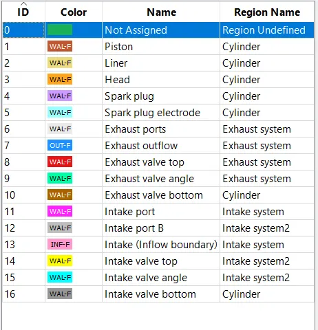
1.Piston:
Type: wall
wall motion type: Translating
surface movment: Moving
Temperature: Law of wall 450K
2.Liner:
Type: wall
wall motion type: stationary
surface movment: Fixed
Temperature: Law of wall 450K
3.Cylinder head:
Type: wall
wall motion type: stationary
surface movment: Fixed
Temperature: Law of wall 450K
4.Spark plug:
Type: wall
wall motion type: stationary
surface movment: Fixed
Temperature: Law of wall 550K
5.Spark plug Electrode:
Type: wall
wall motion type: stationary
surface movment: Fixed
Temperature: Law of wall 550K
6.Exhaust port:
Type: wall
wall motion type: stationary
surface movment: Fixed
Temperature: Law of wall 500K
7.Exhaust Outflow
Type: Outflow
wall motion type: stationary
surface movment: Fixed
Temperature: Law of wall 800K
Pressure : 101325 Pa
Species:
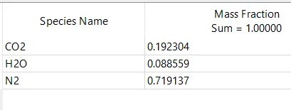
8.Exhaust Valve Top:
Type: wall
wall motion type: Translating
surface movment: Moving Profile: exhaust_lift.in
Temperature: Law of wall 525K
9.Exhaust Valve Angle:
Type: wall
wall motion type: Translating
surface movment: Moving Profile: exhaust_lift.in
Temperature: Law of wall 525K
10.Exhaust Valve bottom:
Type: wall
wall motion type: Translating
surface movment: Moving Profile: exhaust_lift.in
Temperature: Law of wall 525K
11.Intake Port:
Type: wall
wall motion type: stationary
surface movment: Fixed
Temperature: Law of wall 425K
12.Intake Port-B:
Type: wall
wall motion type: stationary
surface movment: Fixed
Temperature: Law of wall 425K
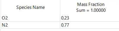
13.Inflow
Type:Inflow
wall motion type: stationary
surface movment: Fixed
Temperature: Law of wall 363K
Pressure : 101325 Pa
Species:
14.Inlet Valve Top:
Type: wall
wall motion type: Translating
surface movment: Moving Profile: intake_lift.in
Temperature: Law of wall 480K
15.Inlet Valve Angle:
Type: wall
wall motion type: Translating
surface movment: Moving Profile: intake_lift.in
Temperature: Law of wall 480K
16.Inlet Valve Bottom:
Type: wall
wall motion type: Translating
surface movment: Moving Profile: intake_lift.in
Temperature: Law of wall 480K
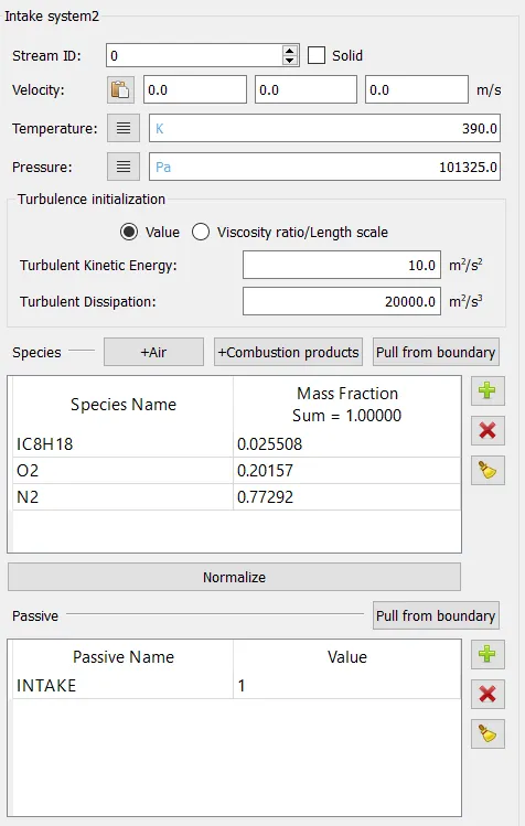
Regions and Initialisation:
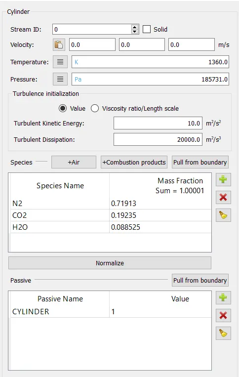
1.Cylinder:
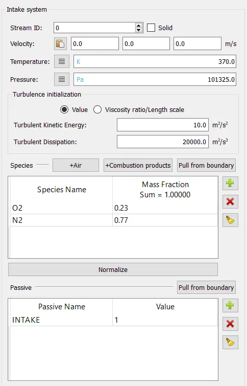
2.Intake System:
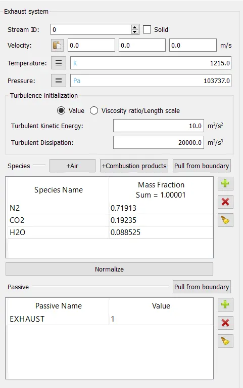
3.Exhaust System:
4.Intake system 2:
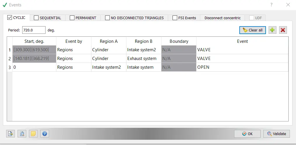
Events:
Events are used to join two regions.
Physical Modelling:
Spray Modelling:
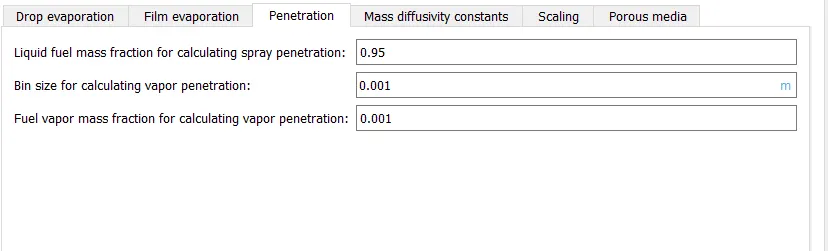
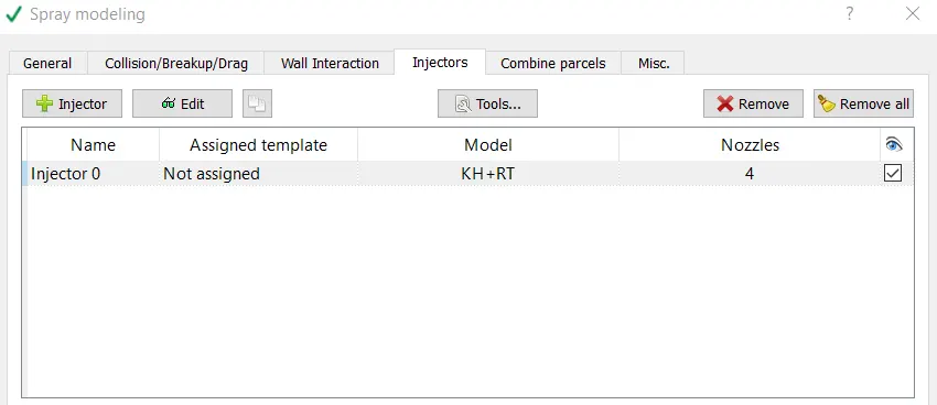
Converge use Langrangian solver to model discrete Parcels and Eulerian solver for continuous phase fluid domain.in Spray modeling define parcel species,evaporation and injector details.
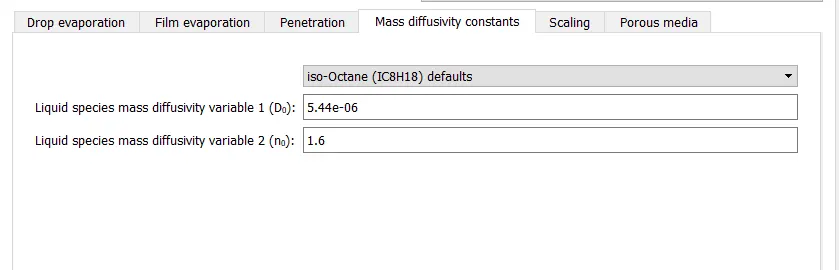
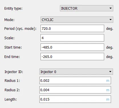
We have used KH-RT model for injectors.This model assumes that only KH instabilities are responsible for drop breakup inside of the characteristic breakup distance, Lb, while both KH and RT mechanisms are activated beyond the breakup length. In this case,CONVERGE first checks if the RT mechanism can break up the droplet. If not, the KH mechanism is responsible for breakup.
Combustion Modelling:
SAGE:
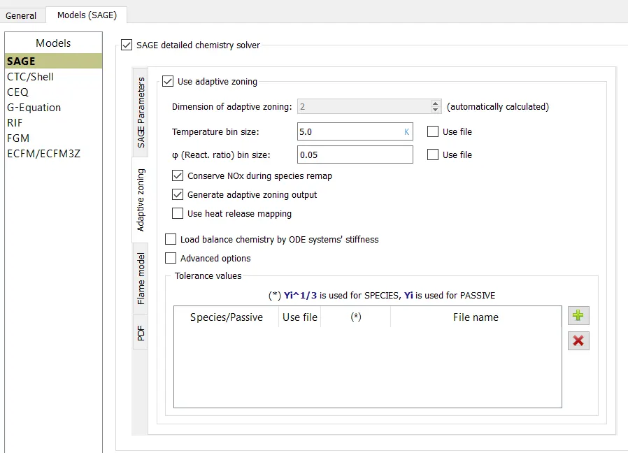
A chemical reaction mechanism is a set of elementary reactions that describe an overall chemical reaction. The combustion of different fuels can be modelled by changing the mechanism. SAGE calculates the reaction rates for each elementary reaction while the CFD solver solves the transport equations.
Turbulence Model: RNG k−ε
Source/Sink Modelling:
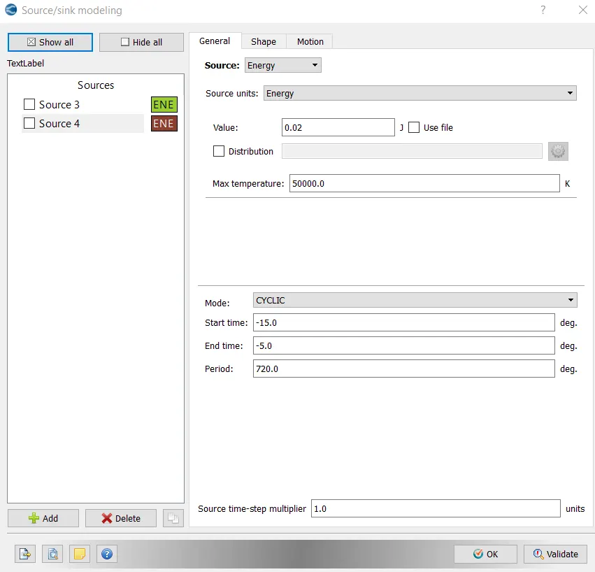
Here we are providing the sources of enrgy.
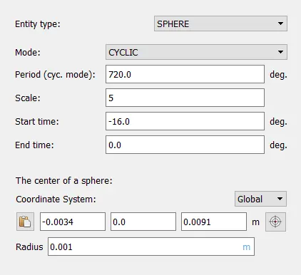
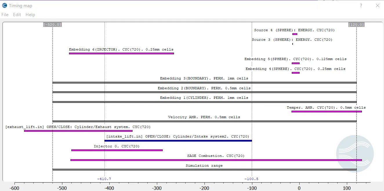
For source 3,wee are saying that for the interval of 0.5 degree wee are providing 0.02 degree.
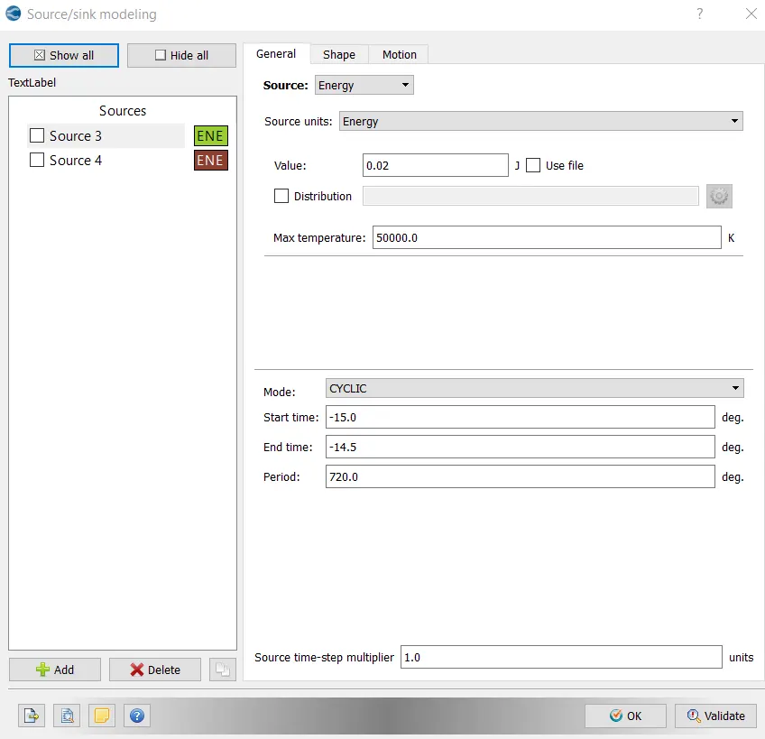
For source 4, for the intreval of 10 degree's we are provoding 0.02 J.It means in total we are provinding 0.04 J of energy from -15 to -14.5 degree interval for source 3.
Grid Control:
Base Grid: 4 mm in all direction.
AMR:
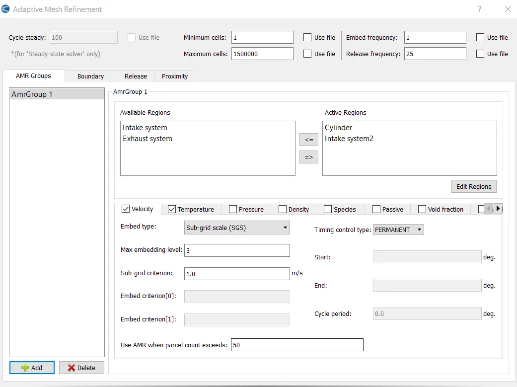
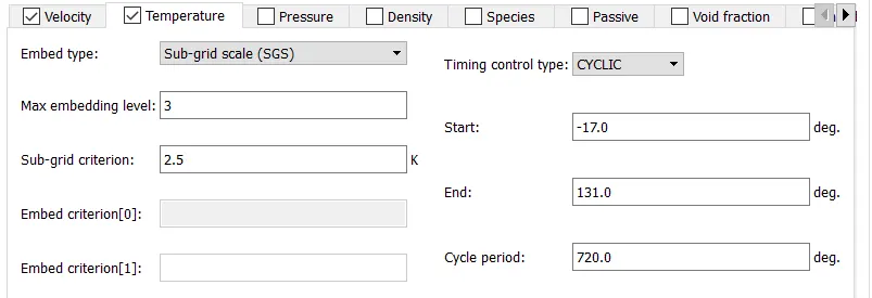
Both velocity and temperature AMR are activated in cylinder regions and intake port (i.e intake system 2).
Fixed Embedding:
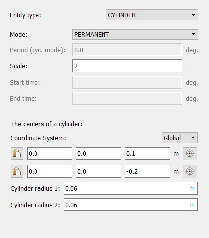
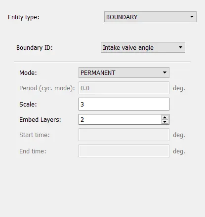
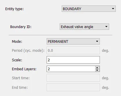
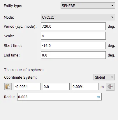
Fixed embedding is done to refine mesh size in particular boundary.
1.Combustion Chamber
2.Intake Valve Angle.
3.Exhaust Valve Angle
4.Sperical embedding
5.Injector:
Timing Map:
Timing map gives details of various activities like valve intake and exhaust,AMR and embedding at diffrent crank angle.
Calculations:
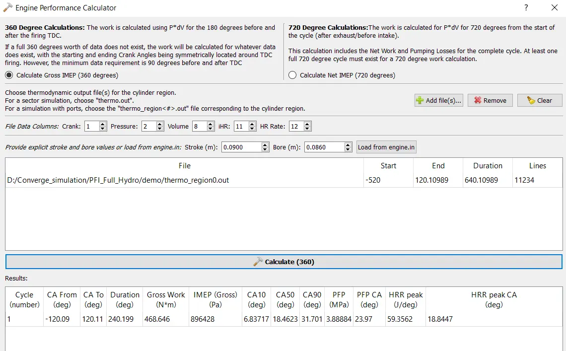
Converge provides engine performance calculator to calculate various performance parameters.
1.Compression Ratio
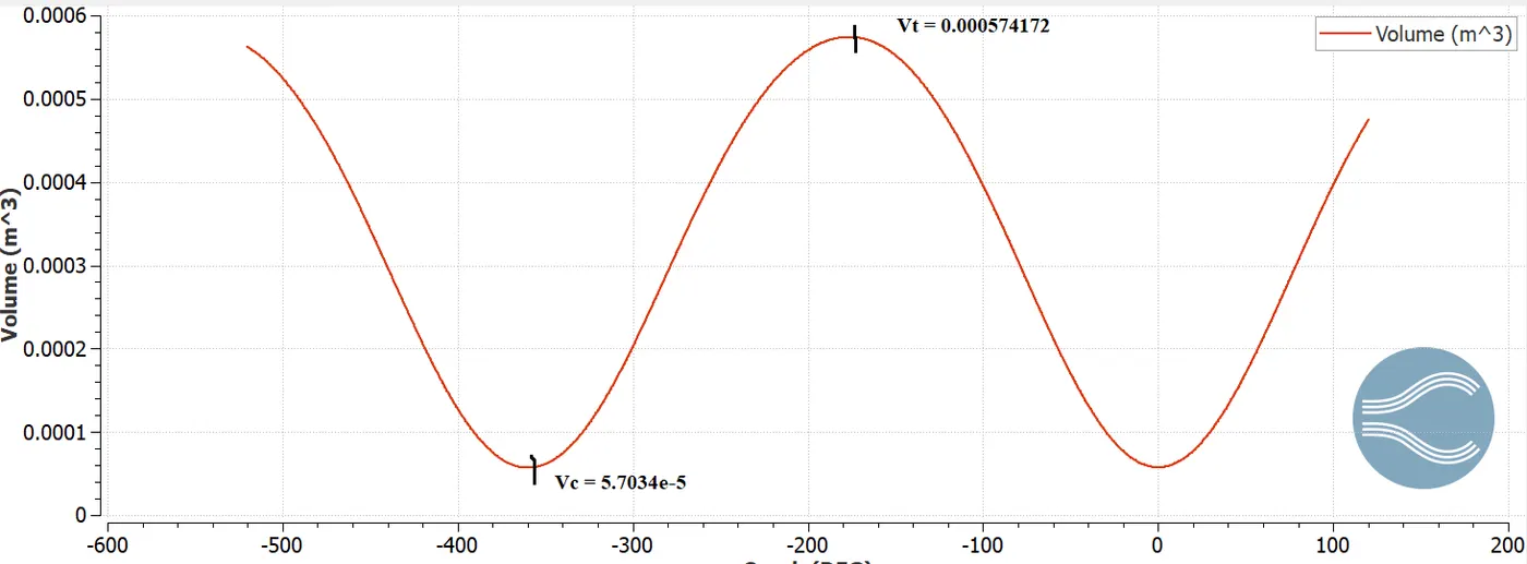
maximum volume = Total volume =0.000574172
Minimum volume = Clearance Volume = 5.7034e-5
Compression Ratio = Total volume/Clearance Volume
= 0.000574172/5.7034e-5
= 10.06
Compression Ratio =10.06
2.Combustion Efficiency
Mass of fuel supplied = 3e-5 kg
Calorific value of IC8H18 = 44427 kJ/kg
Energy supplied = Mass of fuel supplied* Calorific value
= 3e-5*44427
= 1.3328 kJ
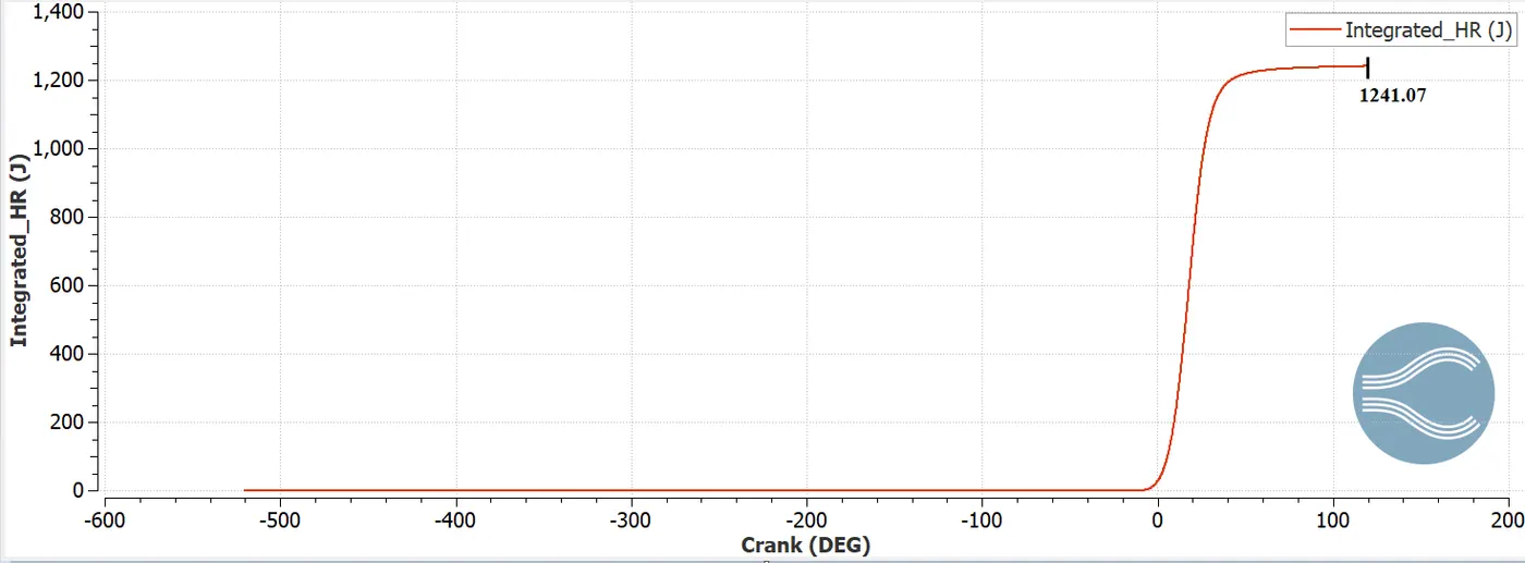
From integrated heat release graph,
Energy output = 1241.07 J = 1.24107 kJ
Combustion Efficiency = Energy output/ Energy supplied
= 1.241/1.3328
= 0.9311 = 93.11%
Combustion Efficiency = 93.11%
3.Power
Speed of engine = 3000 RPM =3000/60 = 50 RPS
Degree per second = 360 *50 = 18000
Duration = 240.199 degree
Time per degree = 240.199/1800 = 0.0133 S
From engine performance calculator,
Work done = 468.646 N-m/cycle
Work done per second = 468.646/0.0133 = 35236.54 J = 35.236 kJ
Power = rate of doing work = Work done per second
Power = 35.236 kJ
4.Torque
We know that,
Power = 2*π*N*T/60
Where,
N = Speed of engine in RPM
T = Torque in N-m
35.236e+3 = 2*π*3000*T/60
T = 112.159 N-m
Why do we need a wall heat transfer model? Why can't we predict the wall temperature from the CFD simulation?
Ans:
Need of wall heat transfer model:
It is known that heat transfer in engine effect the efficiency and emissions. An increase of heat transfer to the combustion chamber walls is lower the in-cylinder pressure and average gas temperature and this reduces the work per cycle transferred to the piston. Thus, the magnitude of engine heat transfer is strongly dependent on engine efficiency. The changes in the gas temperature due to heat loss through the combustion chamber also have an impact on the pollutant emission formation. A higher in-cylinder temperature promotes the NOx emission and the lower in-cylinder temperature causes the particulate during the exhaust.
Prediction of wall heat transfer from CFD simulation:
1.Navier-Stokes equations are the governing equations of fluid dynamics and in general can be solved only numerically. Nowadays there are existing a number of commercial and academic codes for this purpose.
2. Most of them are based on finite volume method. In this method the computational domain is being decomposed at a number of small finite volumes or computational cells. This process of decomposition is called meshing.
3.The bodies in the flow are often treated as “voids” or “holes” in the mesh. The surface of the body becomes one of the boundaries of the computational domain and the appropriate boundary conditions must be set on it to obtain the numerical solution.
4.For incompressible flows we have to solve only for momentum equations (i.e. equations for components of fluid velocity vector). For such a case treating a body as a “hole” in the mesh seems to be a reasonable approach.
5.if we need a solution for compressible flow, In this case we have to solve one additional equation – energy equation, i.e. equation for temperature or enthalpy. In this case we also need a boundary condition for energy equation at the surface of the body called adiabatic wall condition. Applying this boundary condition, we assume that there is no heat transfer between the body and the flow.
What is the significance of ca10, ca50 and ca90?
Ans:
Mass fraction burned (MFB) is the process of chemical energy release as a function of crank angle.
ca10 describes that there is 10% release of enrgy and 90% of fuel is still unburnt.
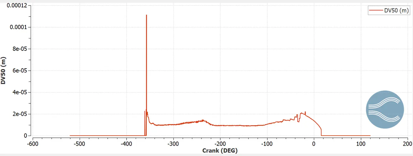
ca 50 describes that there is 50% release of enrgy and 50% of fuel is still unburnt and it is important parameter for egine analysis.
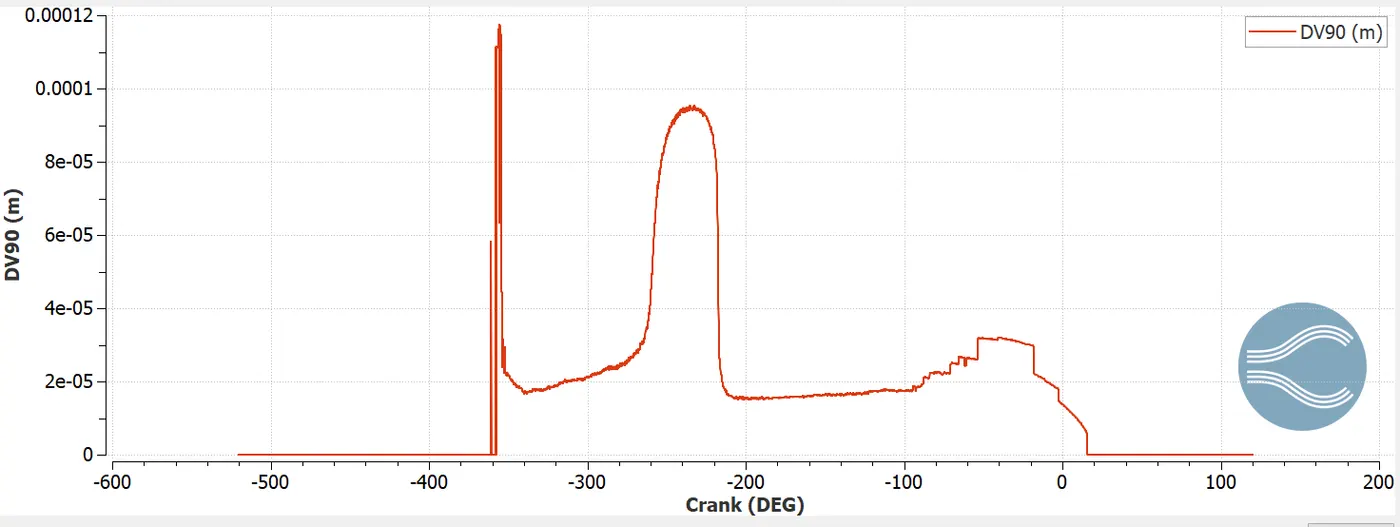
ca90 describes that there is 90% release of enrgy and 10% of fuel is still unburnt.
From engine performance calculator,
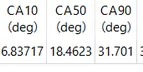
ca10
ca50
ca90
Result:
Pressure:
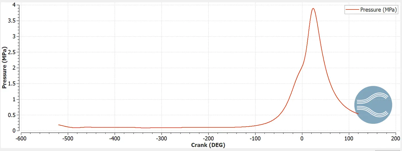
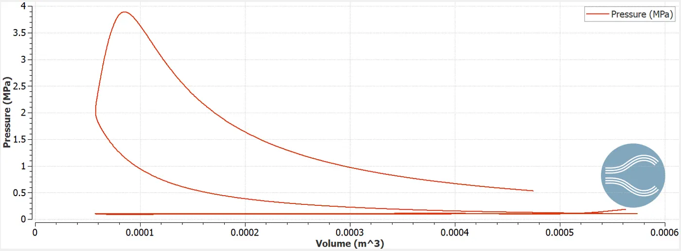
Maximum pressure in combustion chamber is found to be 3.88 MPa.
Mean temperature:
Integrated Heat release:
Energy gained from engine is found to 1241.07 J
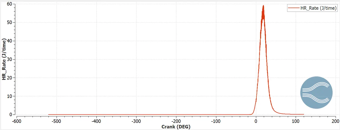
Heat Release Rate:
P-v diagram:
Animation:
1.Mesh
2.Temperature contour
3.Pressure contour
4.Temperature variation inside Combustion chamber