Numerical Analysis of Transient Flow Over a Cylinder
In this project, transient 3D simulation of flow of air over a cylinder of diameter 0.02m and length 0.2m is performed using Flow Simulations add in of Solidworks.
The cross-section of the cylinder is in the XY plane, while its length is in the z direction. The free stream velocity is in the X direction.
Initial studies are carried out with free stream velocity of 1 m/s which corresponds to a flow Re = 1324.32 over the cylinder.
In external flow simulations, its very important to choose the right computational domain. Typically, 5D length in the upstream direction is taken while a minimum of 10D length is taken in the downstream direction of the object to effectively capture the wake. Selection of an optimum domain size becomes important because a small domain won't capture the wake properly while a very large domain would be computationally heavy.
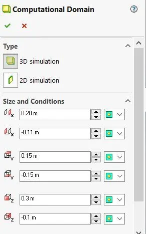
Simulations were carried out for different sized computational domains to select the right domain for our simulations. The details of their sizes and the velocity contours in the XY plane are given below: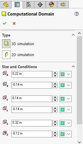
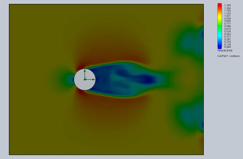
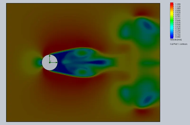
From the contour plots, it is very clear that the smaller domain is clearly missing out details of the wake which would have remained unknown to us until simulations were carried out with the larger domain. So, the smaller sized domain would compute wrong properties around the flow according to the wake calculated by it.
The larger sized domain is chosen for further studies.
MESH REFINEMENT STUDY
A grid independence study was performed to find the optimum mesh for carrying out simulations. The details of the different grid sizes taken are as follows: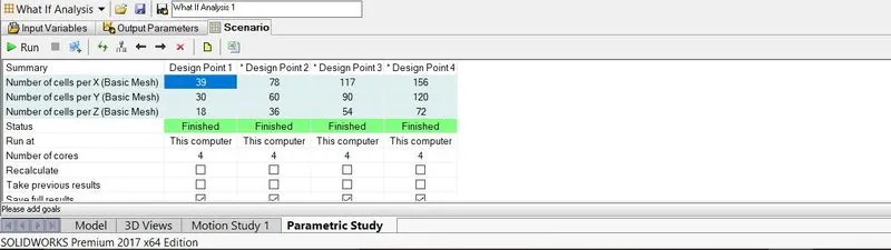
The results for the different design point are as follows:
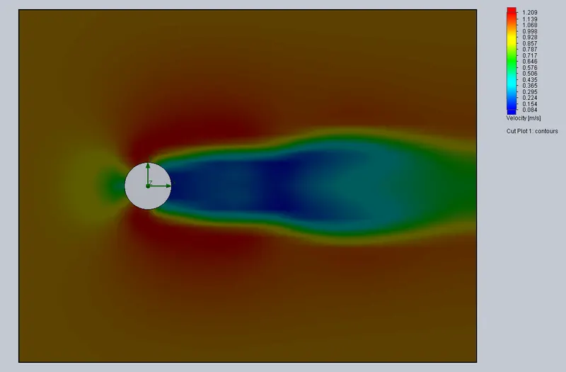
1. Design Point 1
2. Design Point 2
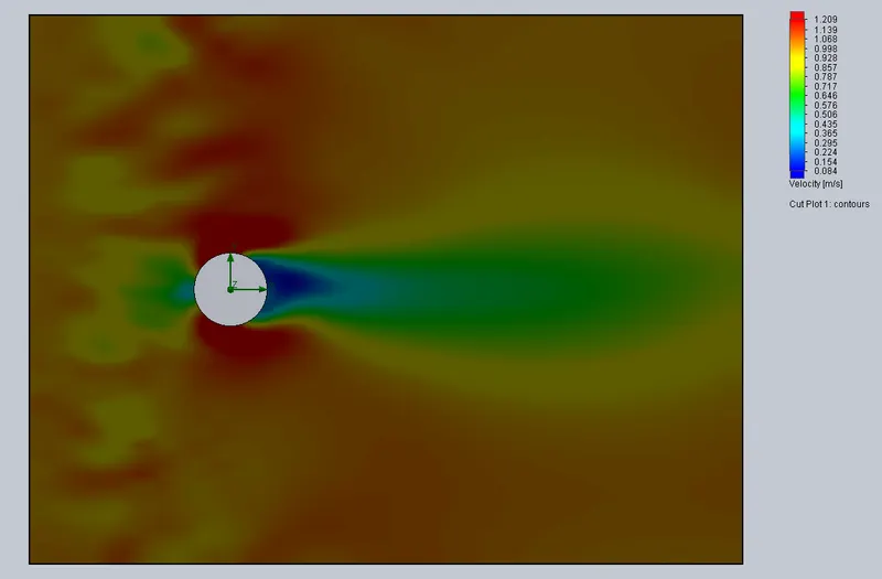
3. Design Point 3
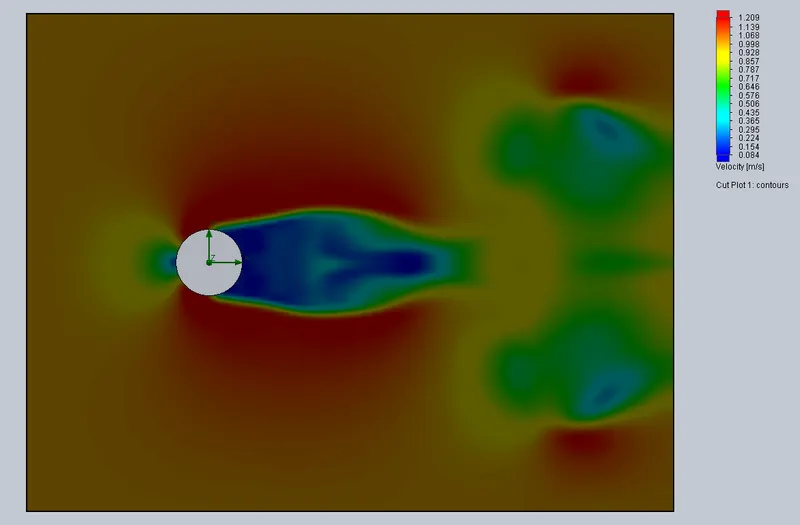
4. Design Point 4
The velocity contours reveal that design points 1 & 2 are giving physically incorrect results, the structure of wake captured by them is wrong which is revealed by the results of the design points 3 and 4. Design Point 4 is giving a better resolved wake structure than design point 3. Further refinement would have given even more details, but carrying out simulations for design point 4 was consuming high computational resources. So, further refinement was ruled. Moreover, design point 4 was giving quite a good picture of the flow behaviour. Hence, design point 4 was chosen for further simulations.
VELOCITY CONTOUR PLOTS
1. XY PLANE
The wake structure behind the cylinder is clearly visible. We can also see the separation of flow in the back side of the cylinder.
2. YZ PLANE
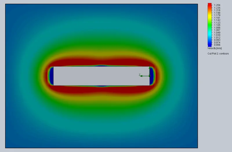
We can see that except some end and edge effects, there is not much variation in the flow domain and the velocity is almost uniform and equal to the free stream velocity in this plane. The velocity gradient seems to be stronger in the y direction compared to the z direction.
2. XZ PLANE
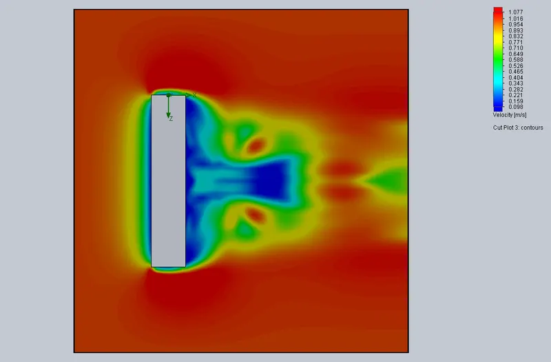
This plot also reveals the fact that gradients along z aren't that dominant as those along x. Wake structures are also more prominent in the x direction only.
Thus, we can see that most of the action takes place along the x and y directions only and thus XY plane contours are enough to study the phenomenon.
VARIATION OF RE
1. v = 1 m/s, Re = 1324.32, t = 0.6s
Velocity Contour
Pressure Contour
2. v = 1.2 m/s, Re = 1589.19, t=0.5s
Velocity Contour
Pressure Contour
3. v = 1.4 m/s, Re = 1854.05, t=0.44s
Velocity Contour
Pressure Contour
4. v = 2 m/s, Re = 2648.65, t=0.3s
Velocity Contour
Pressure Contour
From the above animations, we can see how the flow structure develops around the cylinder. The transient behaviour in the wake region is very well visible. The cylinder induces a transient wake in the downstream region of the otherwise uniform flow. We can also notice how the incoming flow is pushing the wake. The pressure variation is not very strong, however, there exists a strong velocity gradient in the wake region.
As the Re increases, the development of wake takes place at a faster rate and higher velocities are observed. For the range of Reynolds number studied, the flow behaviour and the wake structure is consistent which implies that the flow is still laminar and there is no transition/turbulence.
It can also be noticed that for the duration of the simulation, steady state has not been reached - the wake is still evolving.