No hydro simulation for PFI engine
Aim:
To setup No Hydro Simulation for 4 stroke port fuel injection engine.
Objective:
1.To setup No hydro simulation for PFI engien.
2.To perform surface preparation and boundary flagging for PFI.
Theory:
4 stroke PFI type engine geometry is given and we have to flag the boundaries and check for any geometric errors and eliminaye them.Set the boundary conditions and run No hydro simulation.In No hydro simulation there is no reactions involved and we have check only for mesh and moving parts.
Geometry:
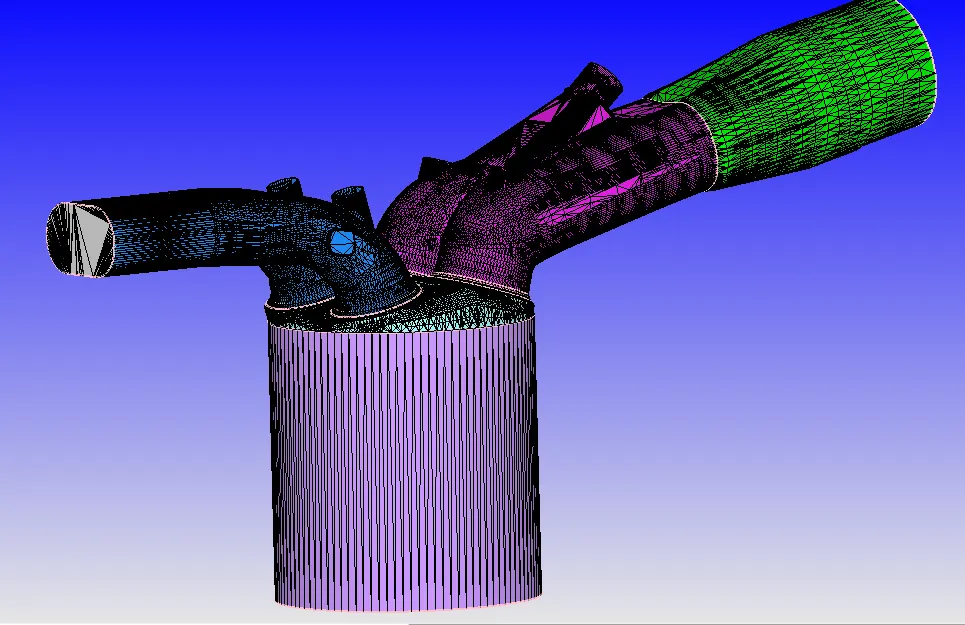
Fig: 4 stroke PFI engine
Piston and liner:
To select pistongo to triangle and selct by triangle method and add piston as boundary and to mark the fence on top and bottom select liner as boundary.
Cylinder Head:
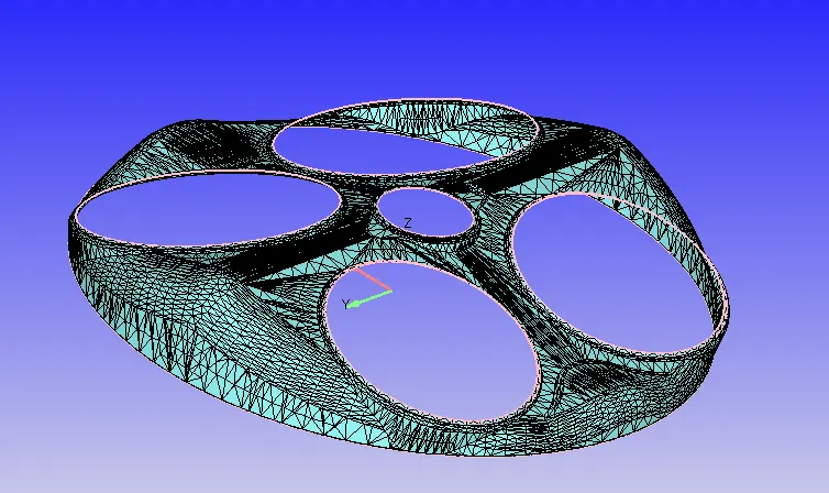
To select cylinder head as boundary mark fences at inlet ,exhaust port and at top of liner and select by boundary fence.
Spark plug and spark terminal:
select an arc surrounding spark plug and mark the fence and select it as boundary.Now to add spark plug terminal as boundary go to fence and click on reconstruct fence from existing boundary,thesee feature will mark fence where edge is in contact with different boundaries.
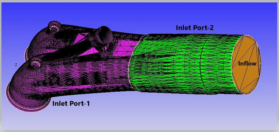
Inlet Port-1,Inlet Port-2 and Inflow:
Here, we have divided inlet port into inlet port-1 and inlet port-2 to provide better initial conditions.
Valves:
There are two types valves in engine: Inlet and exhaust valves.
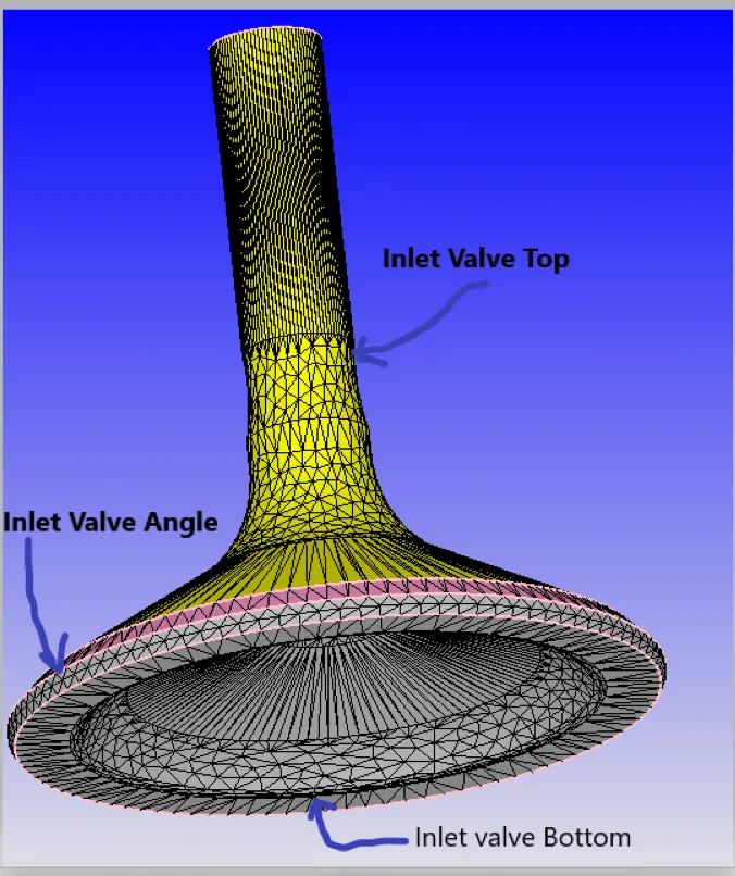
Here,we have divided inlet and exhaust valves further into three boundaries namely Top,Angle and Bottom.
By dividing valves into three different boundaries we can provide additional embedding near valve angle to resolve flow field perfectly.
Inlet Valve:
Exhaust Valve:
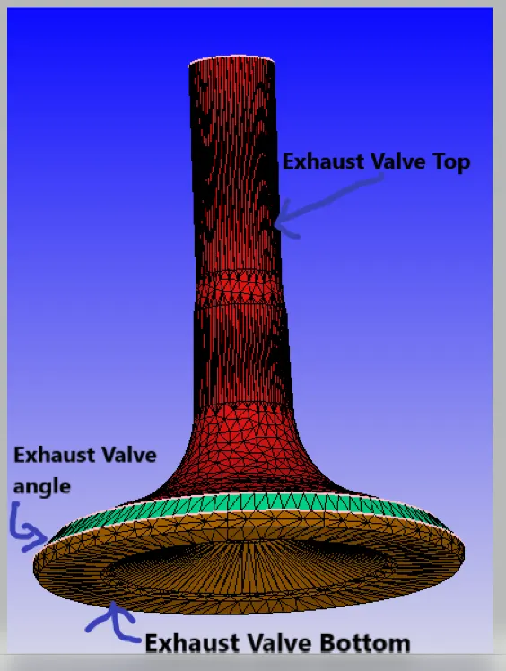
Exhaust valve:
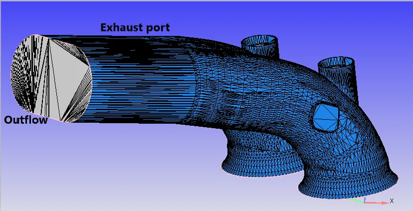
Error Diagnosis:
Click on diagnosis tab and click on find errors.
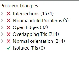
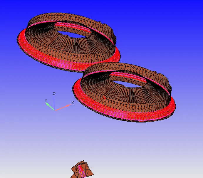
1.Intersection Error:
intersection error occure because inlet valve trianles are overlaping the triangles of inlet port-1.To eliminate these error go to geometry > measure > direction > arc normal and select three point on arc and copy arc nomal coordinates and go to geometry > tranform > translate > select boundaries and copy arc normal coordinates and translate inlet valve.
2.Nomanifold problem and overlaping tris:
If the single edge is shared by more than two triangles then that edge is called Nomanifold edge.
Now,select the overlaping triagles and delete them and to fill void space select the vertices and stitch them.
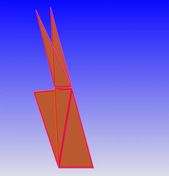
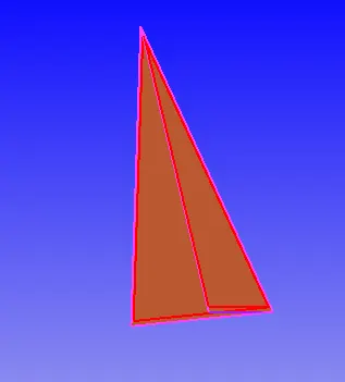
Fig: Nomanifold problems Fig: Overlapping triangles
3.Open Edges:
to select open edges, go to triangles and select by open edge and patch them.
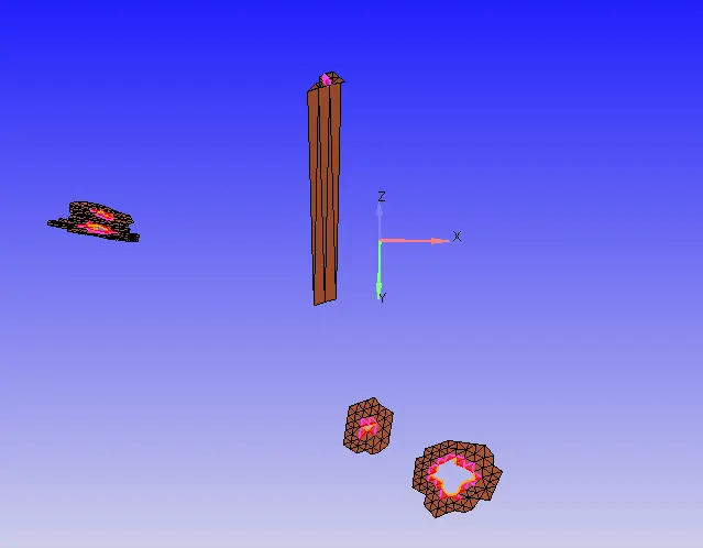
4.Normal orientation:
To eliminate this error,check the direction of normal vectors if the direction of all vectors are not in same direction the go to geometry > transform > normal and select triangle whose normal vector direction is to be changedand click on apply.
Case Setup:
Application type: Crank Angle based IC engine
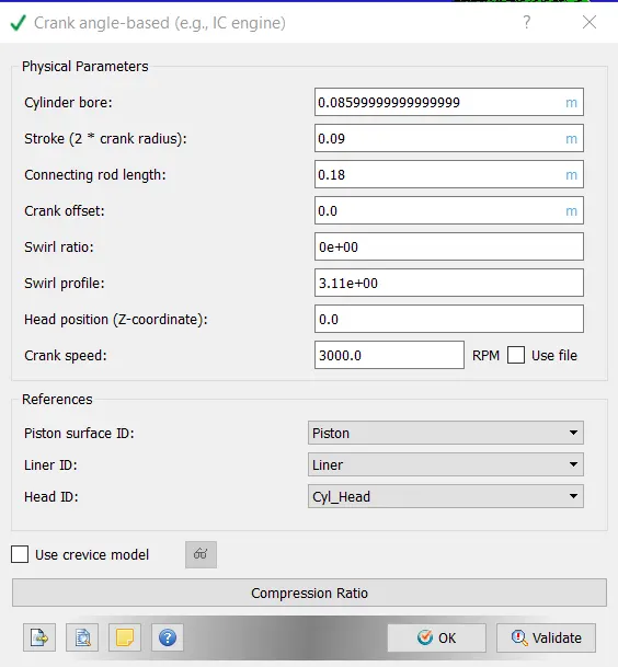
Materials:
gas simulation: import therm.dat file
Reaction Mechanism: import mech.dat
Run parameters: No Hydrodynamic Solver
Simulation Time parameters:
Start time = -480 deg
End time = -480 + 720 = 240 deg
Initial time step = 1e-7
Minimum time step = 1e-8 s
Maximum time step= 0.0001 s
Boundary Conditions:
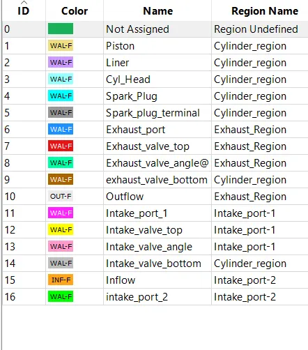
1.Piston:
Type: wall
wall motion type: Translating
surface movment: Moving
Temperature: Law of wall 450K
2.Liner:
Type: wall
wall motion type: stationary
surface movment: Fixed
Temperature: Law of wall 450K
3.Cylinder head:
Type: wall
wall motion type: stationary
surface movment: Fixed
Temperature: Law of wall 450K
4.Spark plug:
Type: wall
wall motion type: stationary
surface movment: Fixed
Temperature: Law of wall 550K
5.Spark plug terminal:
Type: wall
wall motion type: stationary
surface movment: Fixed
Temperature: Law of wall 550K
6.Exhaust port:
Type: wall
wall motion type: stationary
surface movment: Fixed
Temperature: Law of wall 500K
7.Exhaust Valve Top:
Type: wall
wall motion type: Translating
surface movment: Moving Profile: exhaust_lift.in
Temperature: Law of wall 525K
8.Exhaust Valve Angle:
Type: wall
wall motion type: Translating
surface movment: Moving Profile: exhaust_lift.in
Temperature: Law of wall 525K
9.Exhaust Valve bottom:
Type: wall
wall motion type: Translating
surface movment: Moving Profile: exhaust_lift.in
Temperature: Law of wall 525K
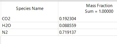
10.Outflow
Type: Outflow
wall motion type: stationary
surface movment: Fixed
Temperature: Law of wall 800K
Pressure : 101325 Pa
Species:
11.Intake Port-1:
Type: wall
wall motion type: stationary
surface movment: Fixed
Temperature: Law of wall 425K
12.Inlet Valve Top:
Type: wall
wall motion type: Translating
surface movment: Moving Profile: intake_lift.in
Temperature: Law of wall 480K
13.Inlet Valve Angle:
Type: wall
wall motion type: Translating
surface movment: Moving Profile: intake_lift.in
Temperature: Law of wall 480K
14.Inlet Valve Bottom:
Type: wall
wall motion type: Translating
surface movment: Moving Profile: intake_lift.in
Temperature: Law of wall 480K
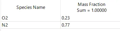
15.Inflow
Type:Inflow
wall motion type: stationary
surface movment: Fixed
Temperature: Law of wall 363K
Pressure : 101325 Pa
Species:
16.Intake Port-2:
Type: wall
wall motion type: stationary
surface movment: Fixed
Temperature: Law of wall 425K
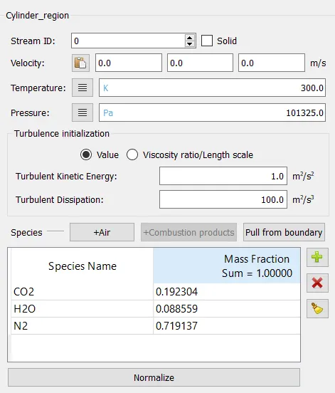
Regions and Initialization:
1.Cylinder Region:
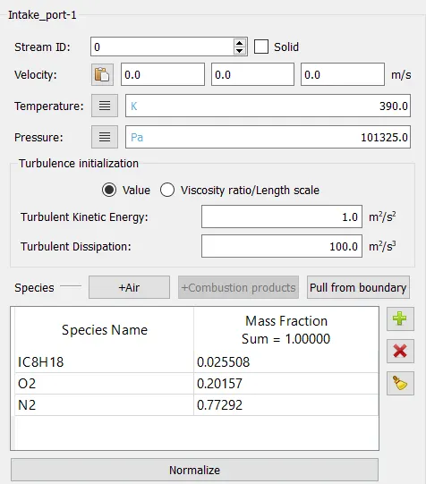
2.intake port-1
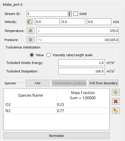
3.Intake Port-2
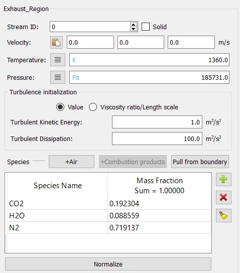
4.Exhaust Region:
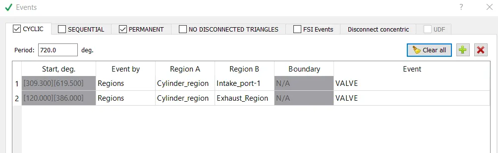
Events:
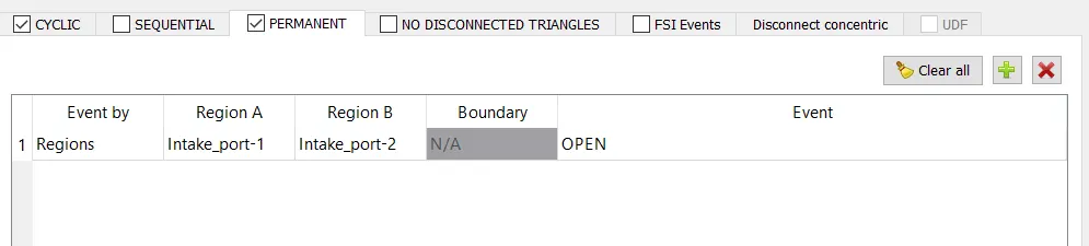
Turbulence Modelling: RNG k-ε
Grid Size:0.004 m x,y,z direction
As 0.004 m is to heavy for my system i have coarsen the grid by providing grid scale of -2.
grid size = base_grid/2^n
= 0.004/2^-2
=0.016 m
Fixed Embedding:
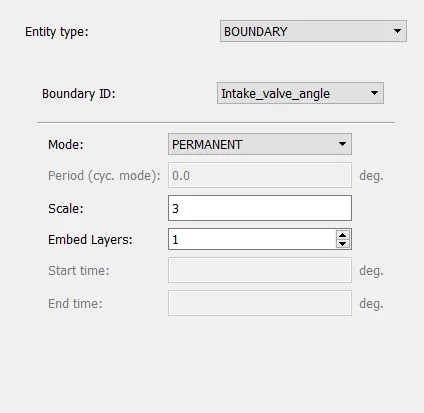
1.Inlet valve Angle:
grid size = base_grid/2^n
= 0.016/2^3
= 0.002 m
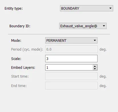
2.Exhaust valve Angle:
grid size = base_grid/2^n
= 0.016/2^3
= 0.002 m
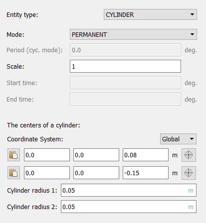
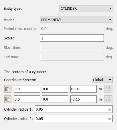
3.Big cylinder Embedding:
grid size = base_grid/2^n
= 0.016/2^1
= 0.016 m
4.Small cylinder Embedding:
grid size = base_grid/2^n
= 0.016/2^2
= 0.004 m
Result:
1.Mesh:
As per shown calculations,mesh is fine near valve angles and coarse inlet and exhaust pipes.
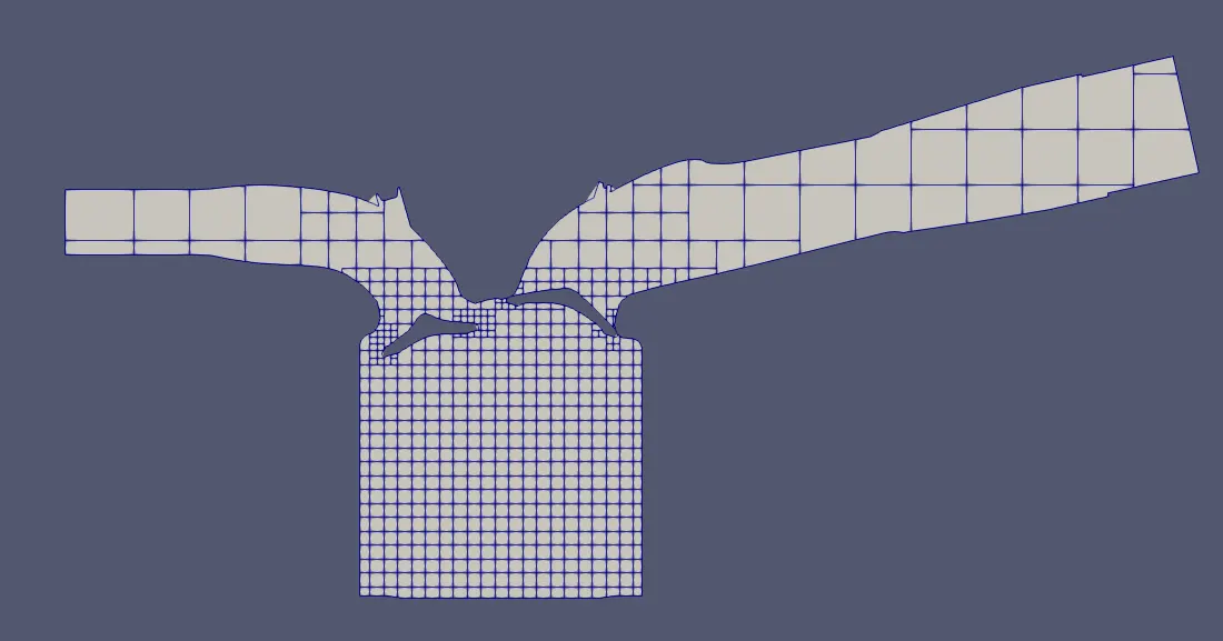
2.Animation of No hydro simulation for PFI engine.