No-hydro simulation of PFI (Port fuel injection) Engine in CONVERGE CFD
Title: No-hydro simulation by Surface preparation & boundry flagging in CONVERGE CFD
Objective : 1. To Understand the boundry flagging & surface preparation on PFI
2. To perform the No-Hydro simulation of PFI Engine
3. To undestand the error came across & explain meaning of each error
Theory:
4-stroke PFI (Port fuel inection) model is given for perform the no- hydro simulation it means that there will not be any reaction only how there is mesh & parts movement is working that will be checkt it. while doing No-hydro simulation there is nedd to do boundry flagging & surface preparation during this period there are many erro come across that can be remove. so, in this challenge important part is to surface preparation & run the no hydro simulation.
3D Geometery
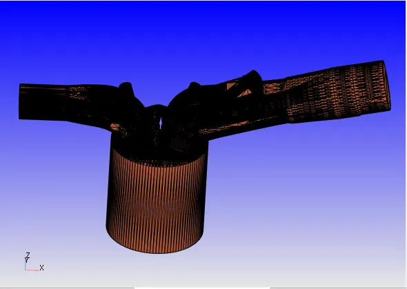
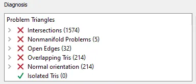
Error occurs in geometery
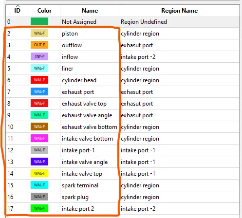
Boundry name is created to remove the Errors
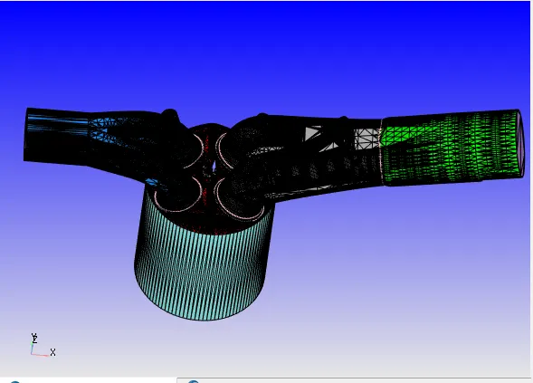
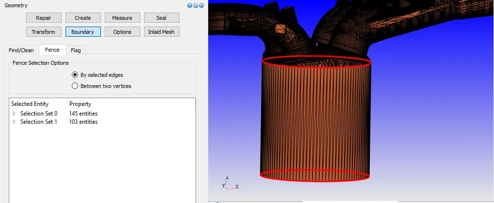
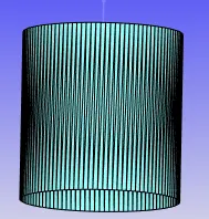
1. Liner
fence to edge by arc method , so that we can flag the liner
2.
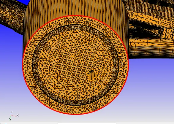
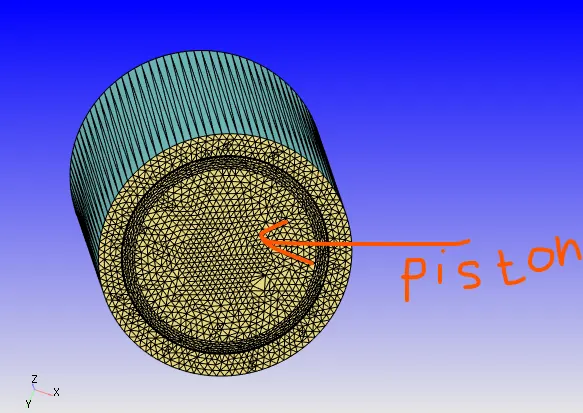
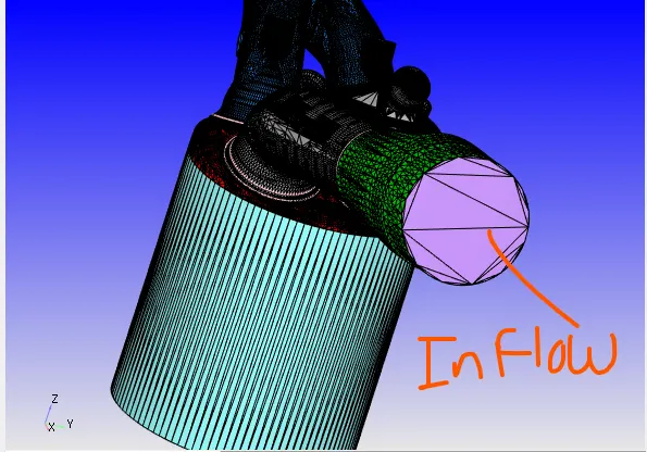
Inflow
by fence method flag the boundry
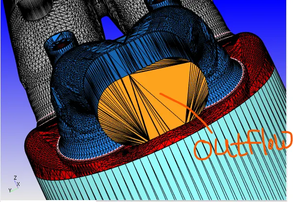
Outflow
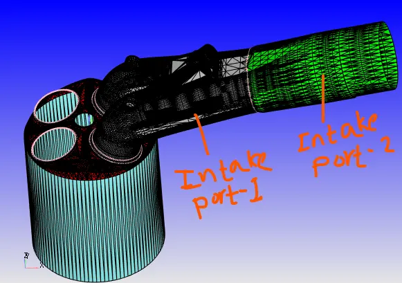
Intake port-1 & 2
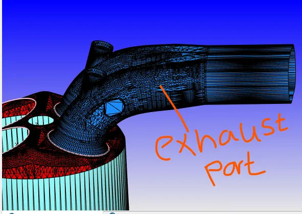
Exhaust port
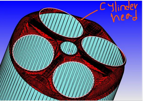
Cylinder head
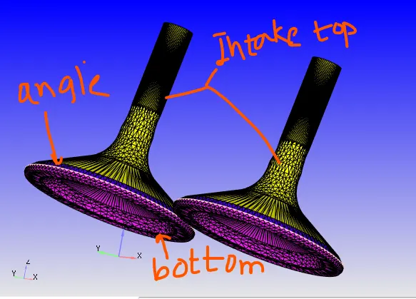
Intake valve top, bottom & angle
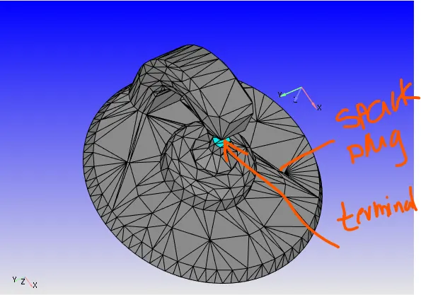
Spark plu & terminal
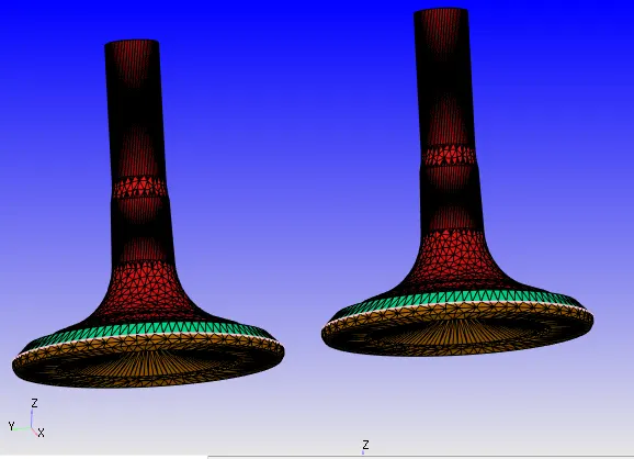
Exhaust valve top, bottom & angle
Type of error
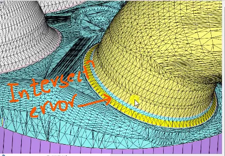
1. Intersection error
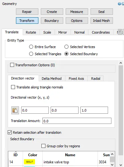
This error occurs due to cylinder head is intersect with intake valve angle then there is intersection error occurs. it can remove by the transform option by the boundry type so there is select the intake top, bottom & angle. it transform by the 0.0001
2.Open edge error
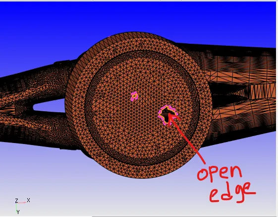
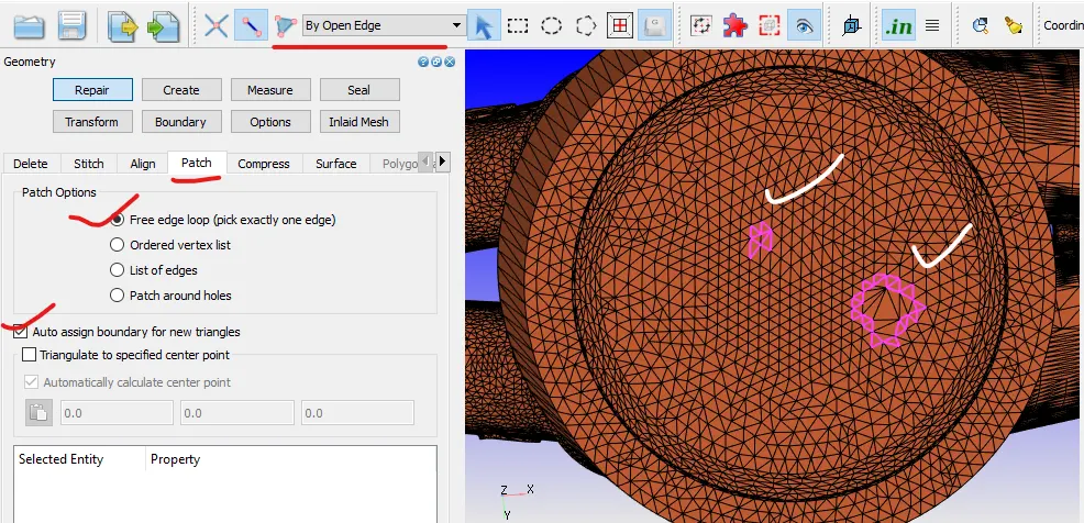
open edge error showing in yellow colour by the patch we can remove it
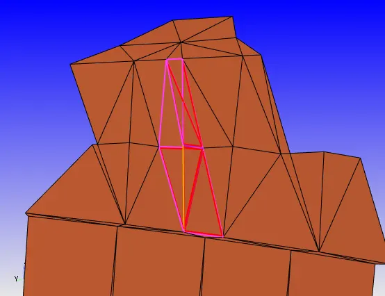
3.Non manifold edge error
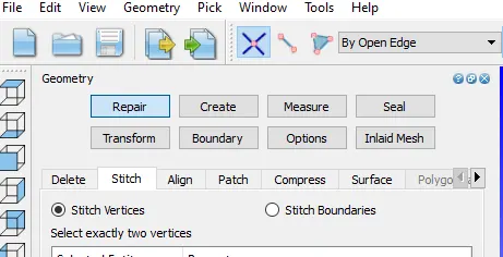
one edge share by three or more trianle then this error occcur & it can be remove by the stich option
4.Normal orientation error
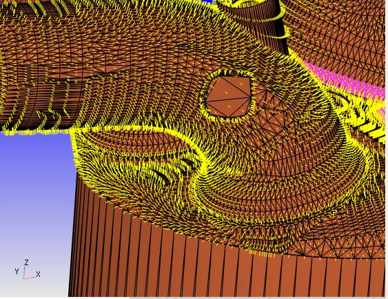
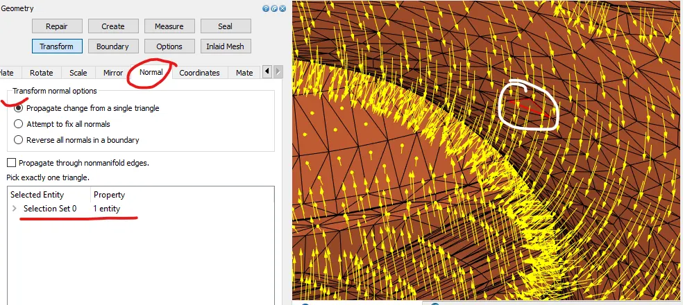
direction of normal should be inside as flow is flowing inside the PFI engine. it can point out to inside by the transform normal inside by select any one traingle
CASE Setup for NO-Hydro
1 Application type -Crank based IC Engine
Cylinder bore=0.0856m
Crank raduis=0.09
Connecting rod length=0.18
Crank speed=3000 rpm
2.Materials
Gas simulation>import them.dat file
Reaction mechanism> import mech.dat
3. Simulation parameter
Solver> Transient
Temporal type> Crank based simulation
Simulation mode> No-hydrodynamic
Simulation time parameter
Start time= -480 deg
End time= 240 deg
Intial time step=1e-7
Intial time step=1e-8
Boundry condtion
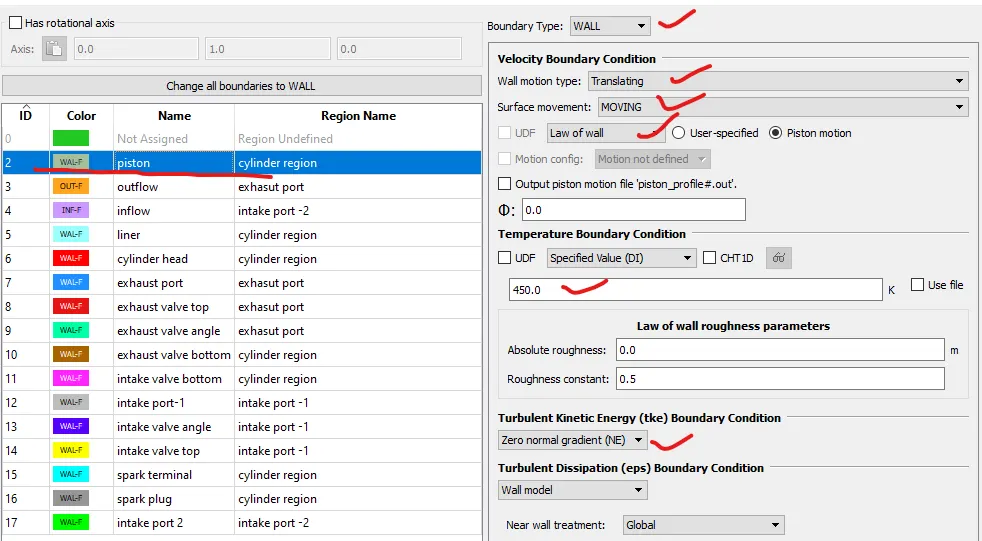
Outflow
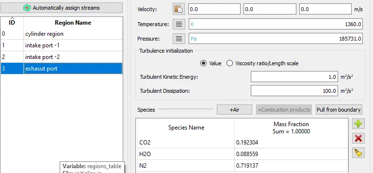
comnustion product is given CO2, N2, H20
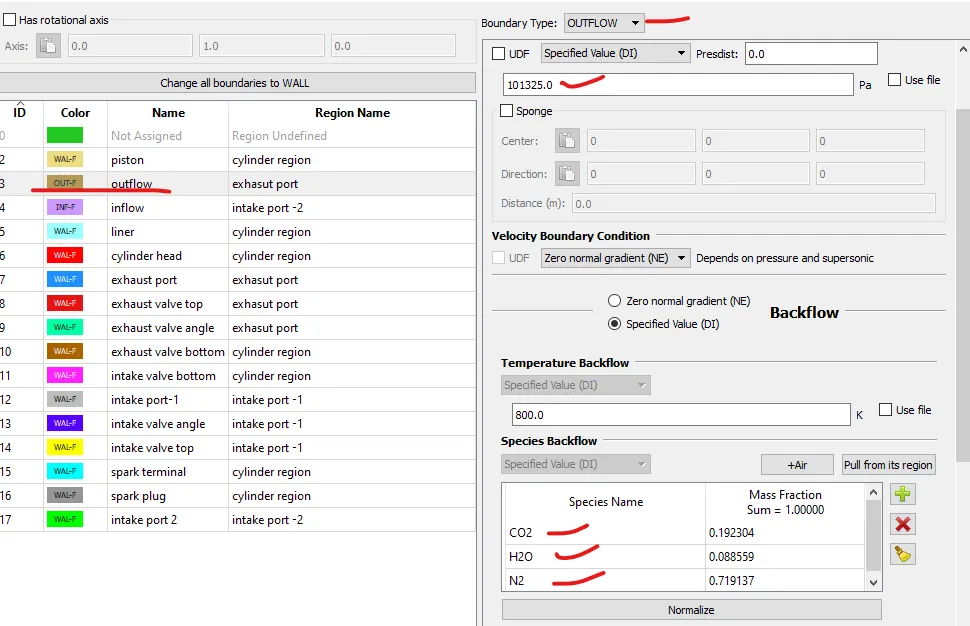
Inflow
at inflow air quantity is flow
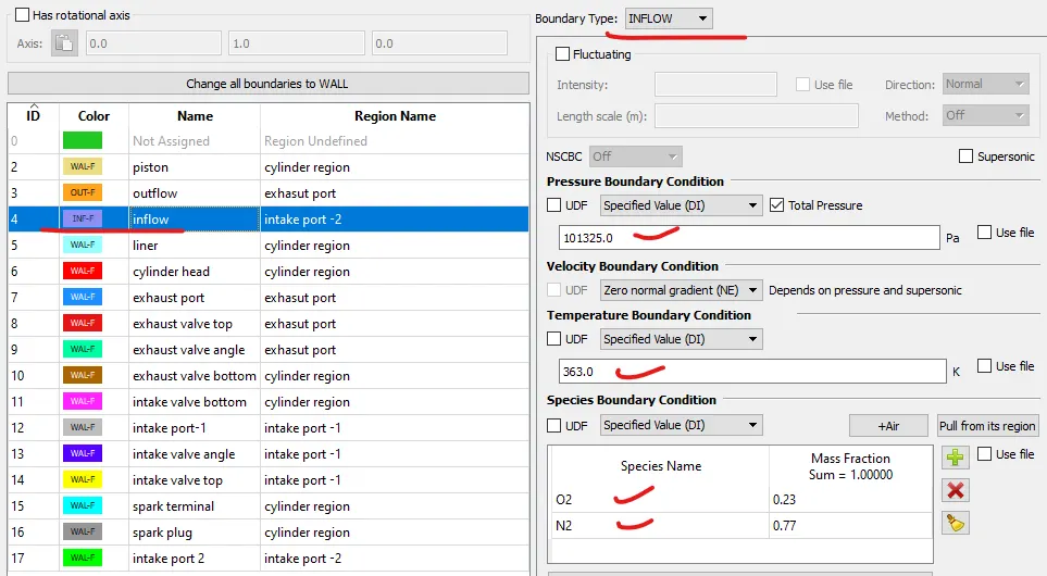
Liner
Boundry type> Wall Surface movement> fixed
motion type>stationary Temp > 450k Turbulent tke> zero normal gradient
Cylinder head
Boundry type> Wall Surface movement> fixed
motion type>stationary Temp > 450k Turbulent tke> zero normal gradient
Exhaust port
Boundry type> Wall Surface movement> fixed
motion type>stationary Temp > 500k Turbulent tke> zero normal gradient
Exhaust valve top
Boundry type> Wall Surface movement>moving profile>exhaust lift.in
wall motion type>Translating Temp > 525k Turbulent tke> zero normal gradient
Exhaust valve angle
Boundry type> Wall Surface movement>moving profile>exhaust lift.in
wall motion type>Translating Temp > 525k Turbulent tke> zero normal gradient
Exhaust valve bottom
Boundry type> Wall Surface movement>moving profile>exhaust lift.in
wall motion type>Translating Temp > 525k Turbulent tke> zero normal gradient
Intake valve bottom
Boundry type> Wall Surface movement>moving profile>intake lift.in
wall motion type>Translating Temp > 480k Turbulent tke> zero normal gradient
Intake valve angle
Boundry type> Wall Surface movement>moving profile>intake lift.in
wall motion type>Translating Temp > 480k Turbulent tke> zero normal gradient
Intake valve top
Boundry type> Wall Surface movement>moving profile>intake lift.in
wall motion type>Translating Temp > 480k Turbulent tke> zero normal gradient
Spark terminal
Boundry type> Wall Surface movement>fixed
wall motion type>Stationary Temp > 600k Turbulent tke> zero normal gradient
Spark plug
Boundry type> Wall Surface movement>fixed
wall motion type>Stationary Temp > 550k Turbulent tke> zero normal gradient
Intake port-1
Boundry type> Wall Surface movement>fixed
wall motion type>Stationary Temp > 425k Turbulent tke> zero normal gradient
Intake port-2
Boundry type> Wall Surface movement>fixed
wall motion type>Stationary Temp > 425k Turbulent tke> zero normal gradient
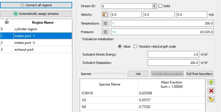
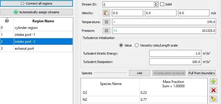
Region & Intialzation
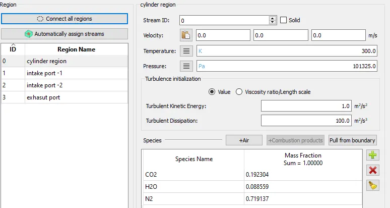
Intake port-1
Intake port-2
exhasut port
Event Created
for flow the fuel from intake port-1 to cylinder region event is created, so that disconnected triangle is created & it will be broken so, that flow of fuel is start, its same for exhaust port after combustion process is over
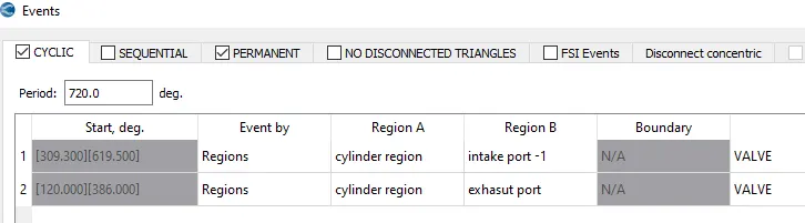
Intake port-1 & 2 is always connected
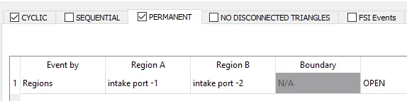
Base grid size= 0.008m
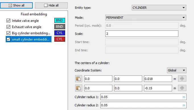
Fixed embedding
1. Intake valve angle
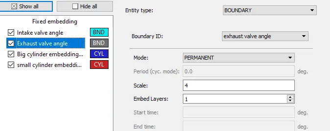
Fixed embedding= (base grid size)/2^n
base grid size uses =0.008m
n=4= scale
Embed layer =1
fixed embedding= 0.008/2^4
= 0.0005 m
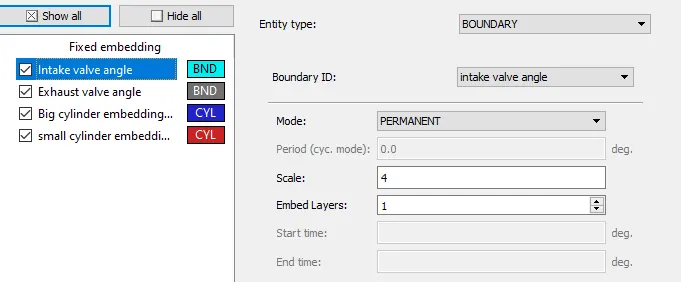
Embed layer =1
fixed embedding= 0.008/2^4
= 0.0005 m
Exhaust valve angle
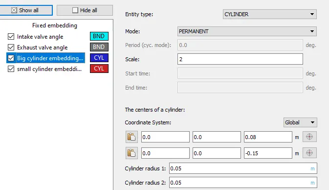
Big Cylinder
Embed layer =1
fixed embedding= 0.008/2^2
= 0.000125 m
Small cylinder embedding
Embed layer =1
fixed embedding= 0.008/2^2
= 0.000125 m
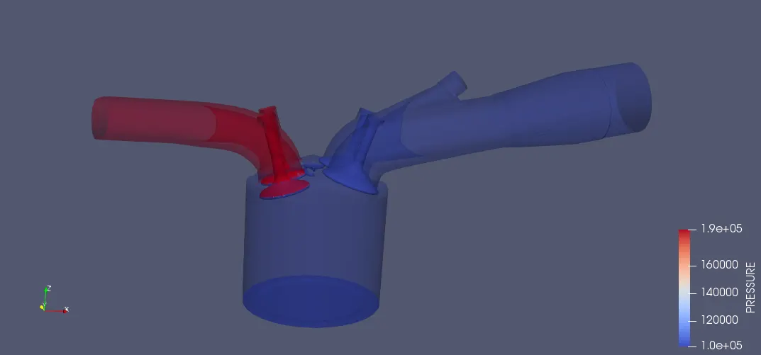
Pressure Contour
High pressure is created on exhaust port due to small area & burnt gas which result in high press
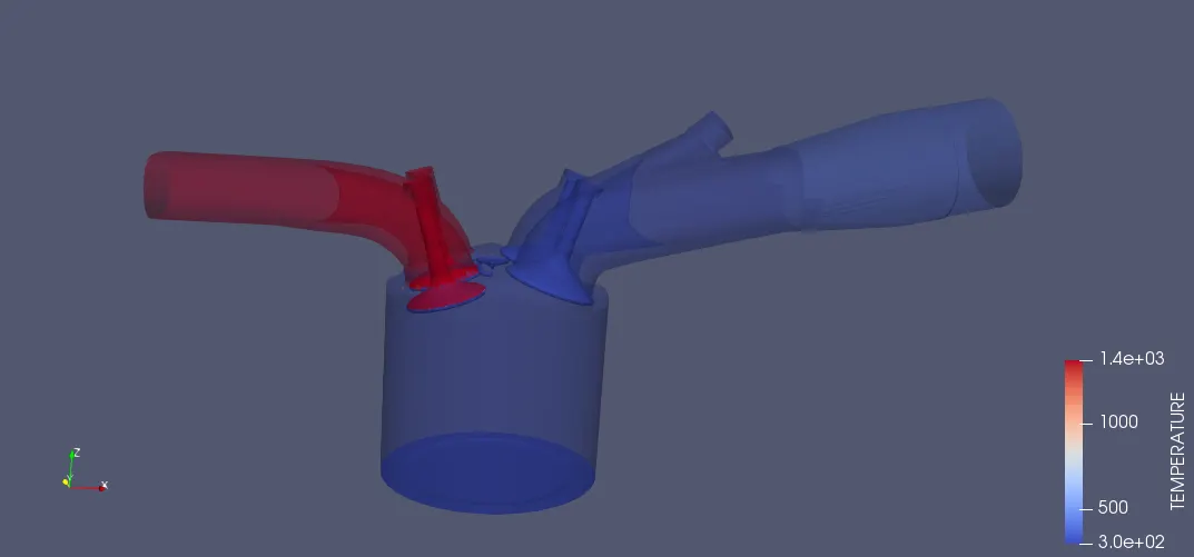
Temprature contour
Temprature is higher at exhaust port due to high pressure as well as burnt gas create high temp
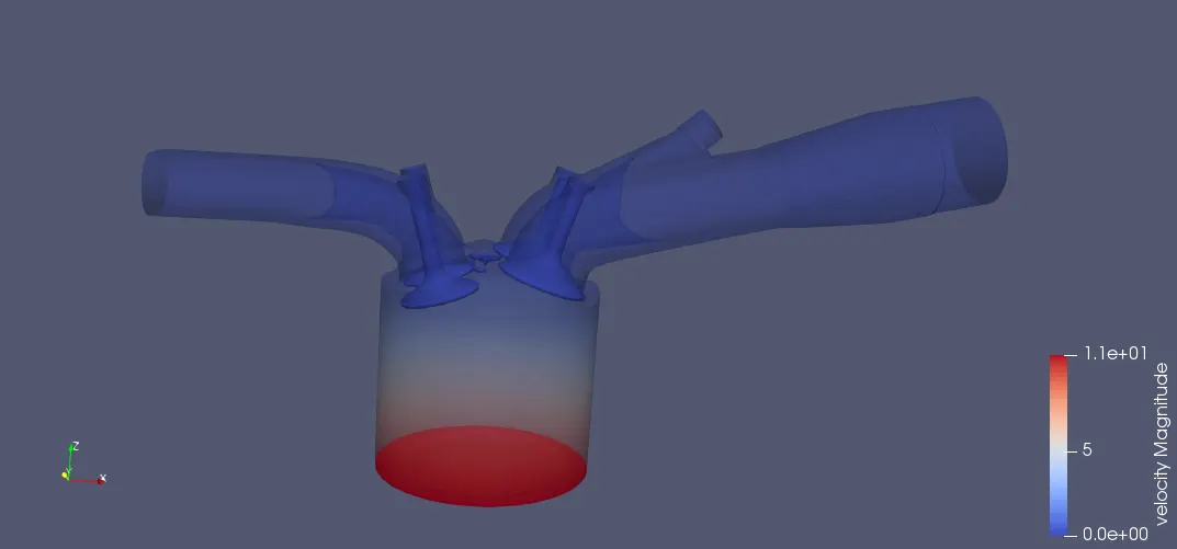
Velocity contour
higher veocity at bottom & lesser velocity at intake & exhaust port
No hydro simulation of PFI Engine
from below video we can there is complete one cycle of power stroke is work.
Overall conclusion
1. Understood how to remove diffrent error like intersection, open edge, normal orientation, non-manifold edge
2. Understood how to create the event , fixed embedding etc.
3. Understood how to flag the boundry for clean up geometery & remove errors
4. Understood how to make setup for sucessful run of PFI simulation