Modelling of an Automotive Seat Frame With Connections by Using ANSA
AIM :
To Perform an Preprocessing operation on a given Seat Structure model by using ANSA.
OBJECTIVES :
To Perform a Geometry Cleanuping on a whole seat frame model.
To Extracting the Middle Surface from the Parent Geometry and assigning into the respective Property card according to thickness of the component.
To Setting the Mesh Parameters and Element Qualities based on features size.
To Perform Shell Meshing with Mixed Elements on the Extracted Middle Surface along with Quality Checking.
To Perform Shell Meshing with Trias Elements on the Solid Part Surface along with checking the element qualities.
To Defining the Volumes for which performing an Volumetric meshing.
To Perform Volumetric meshing with Tetrahedral Elements by using defined volume and checking the qualities.
To Deploying the connection by using Seam, Many Nodes RBE2 Element, Two Nodes RBE2 Element, CBAR & CBEAM 1D Elements.
INTRODUCTION :
Automotive Seat assembly is a very complex structure in any automotives. There are lot of components presented in the seat model assembly such as Arm rest, Back rest with lumber support, Head rest, Seat base, Seat track, etc. These sub components are connected together by using many connections such as Bolts, Rivet, Seam Weld and then Springs as well. The same Connection can be deploying in ANSA with the help of some useful tools. We have to make a connections based on type of analysis such as NVH, Crash, Durability and Structural Analysis.
In this project, we have to discretize the components into infinitesimal control volume or finite number of elements which is called meshing. Finally, to prepare a seat structure model for NVH Analysis by using NASTRAN deck.
CAD Model :
Open a ANSA software, Subsequently Import the appropriated file which is Automotive Seat Frame Structure by using Open Graphical User Interface Option.
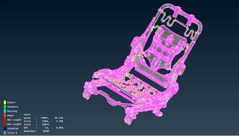
Once, a file has been opened, it will be visible from the graphical area and it's looks like as shown in the below image.
We can able to see, a each and every macros are not connected to eachother due to given model had been transformation from design tool to Preprocessor tool like ANSA.
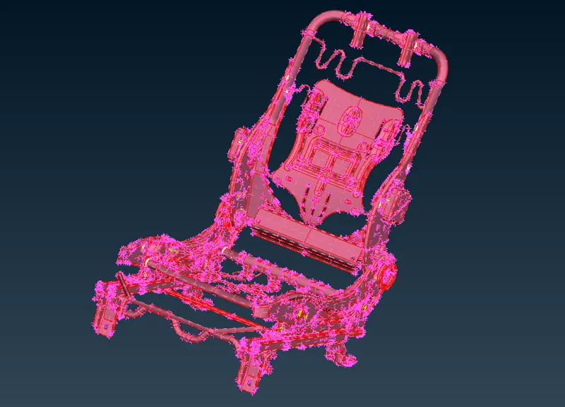
Usually, a Spot points are appeared from corner of the macros, if it's not connected to each other. By results, a spot points are appeared like as in below image.
PROCEDURE FOR ACHIEVING THE OBJECTIVES :
I) Geometry Cleanuping :
i) Topology Cleanup :
As We can clearly see from the imported model, there's no surfaces or macros are connected to each other, by results Free edges are appeared around the macros. Inorder to rectify those issues from the model, we should be use "Topo" Option under where "Faces" sub module and "Topology" main module to which join the surfaces together like as shown in below image.
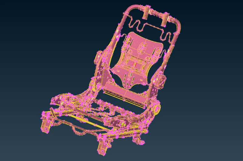
A "Topo" option have some tolarence value by default, if the two cons lateral distance is less than or equal to which tolarence value of topo option, by result two cons are connected each other while performing an "Topo" process.
Some where two parts are located very closely or let say, a distance between two component surfaces is less than that tolarence value of the Topo option. By result, we end up with triple cons, we will clear those issues while checking the geometry by using check manager.
ii) Geometry Checking :
Before going to extract the middle surface from the parent component. Make Sure we have to checking the entire geometry if there's any geometrical errors are presented or Not.
ANSA have by default template with which have prebulided some few important parameters. Make Sure we have check all those parameters except "Sharped Edges" and "Unmeshed Macros"
After completing the parameters selections, make sure keep "Visible On" from the Execute On" Option and then click to proceed.
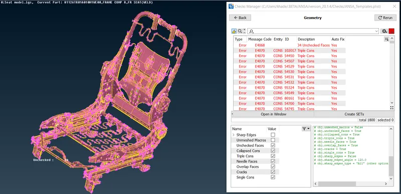
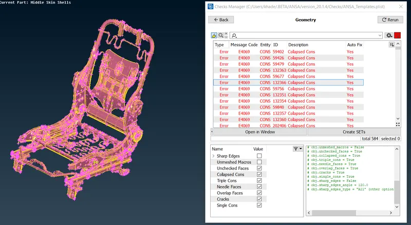
ANSA was findedout lots of errors such as Triple cons, Single cons, Overlapped faces, Collapased cons, Cracks between cons and Needle faces.
Inorder to fix those errors, we have two option in our hand. One is Manual fix and another one is automatic fix. In this case, We are surely going to with automatic fix for Triple cons issue, Overlapped faces, Needle faces & Cracks between Cons. Because as we noticed from the check tab which is "Yes" for "Auto fix". Which means ANSA can able to fix the issues by itself.
Inorder to do fix those thing in automatically, we have to select all errors which are shown up and right click & followingly select to fix option. Afterthat, ANSA have fix those issue in proper manner.
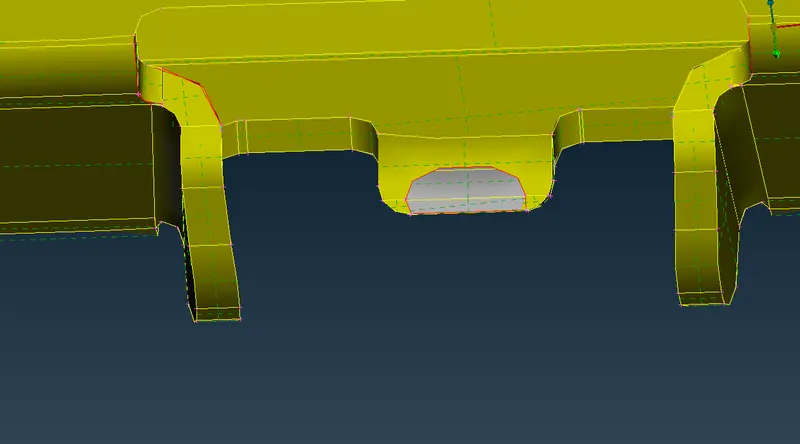
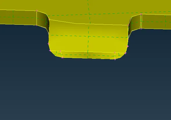
Apart from that, We have to maually fix the some errors like as single cons errors, a single cons issue are created due to missed surface like as shown from below image.
By Using "Fill Hole" Option under where "CONS" Sub module & "Topology" module. After filling the hole, it will looks like as shown in below second image.
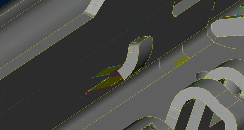
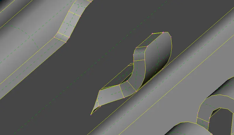
As we can clearly see from the below first image, a Clamp surface had been missed a lot. By Using "Extend", "New Faces", "Intersect" & "Cut" Options are used to create a clamp surface in proper manner like as shown in second below image.
Similarly, one more face is missing as shown in first below image. By using Fill Hole option to which create a missed surface as shown in second below image.
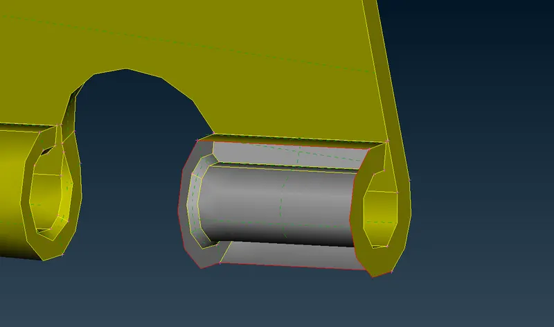
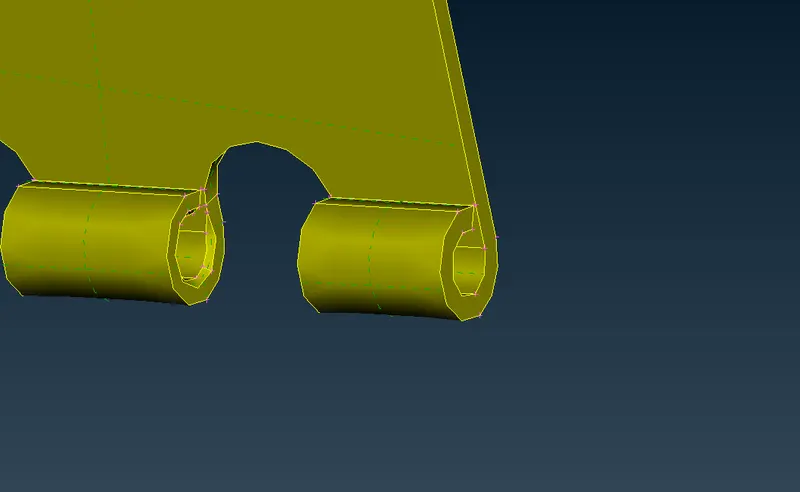
Apart from this, lot more surface are missing as like I mentioned in previously. But, those errors are not affecting while extracting the middle surface. So, we moving on forward to extract the middle surface.
Geometry Cleanuping on Solid Component :
In this Solid Component thickness is more than 5mm, so we will performing volumetric meshing. Inorder to meshing with Volumetric elements, first of all we have to create a shell meshing on the surface of the solid component. Inorder to create a shell meshing, a component should be clean without any geometrical issue.
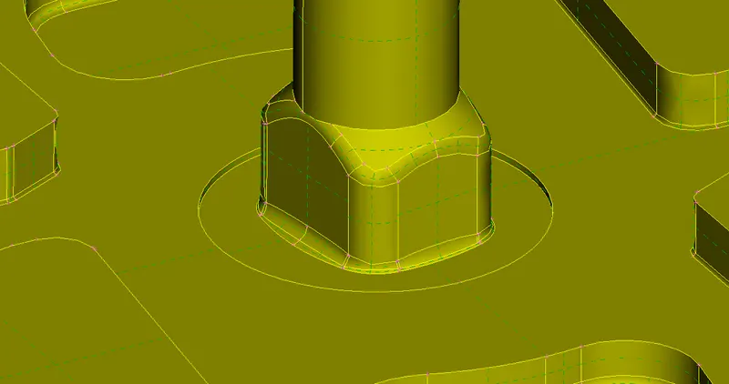
We can clearly see from the below first image, a surfaces are unpatched together. We have to manually creating the new surfaces like as second below image.
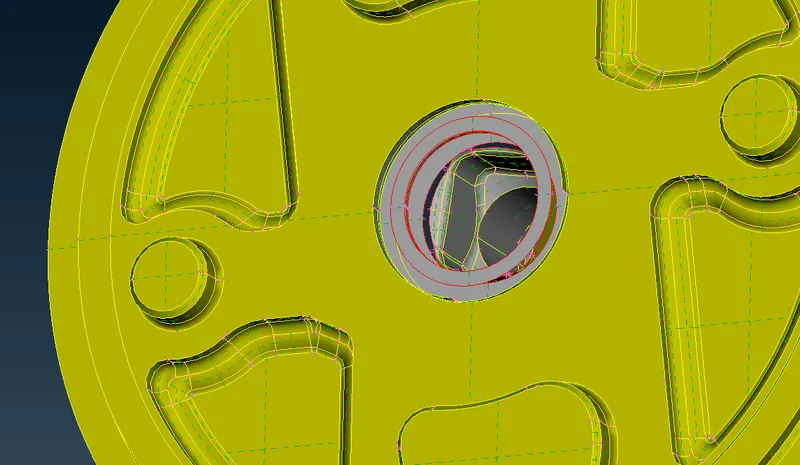
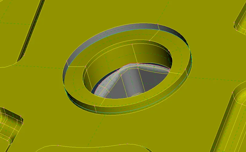
And also, we can extend the surfaces with the help of pairs sub option to get the desired one on top side of the solid component as shown in below image.
Again we have to cross check the geometry by using same template. As shown in the below image, still some error are not yet to be fixed, Even shown up "Yes" for auto fix. Confidently, we should going to next process, because those errors are not affecting the successive process as I mentioned in earlier.
II) Extracting the Middle Surface :
A Seat structure model is exactly symmetrical in shape about an Z axis. So, we have to cut into exactly half by using "Plane Cut" option and work on half a model to save a time.
Inorder to cut into half a portion, select the "Plane Cut" option from where "Faces" Sub Module & "Topology" Module. Choose three points in properly to which fix the plane like as shown in below image.
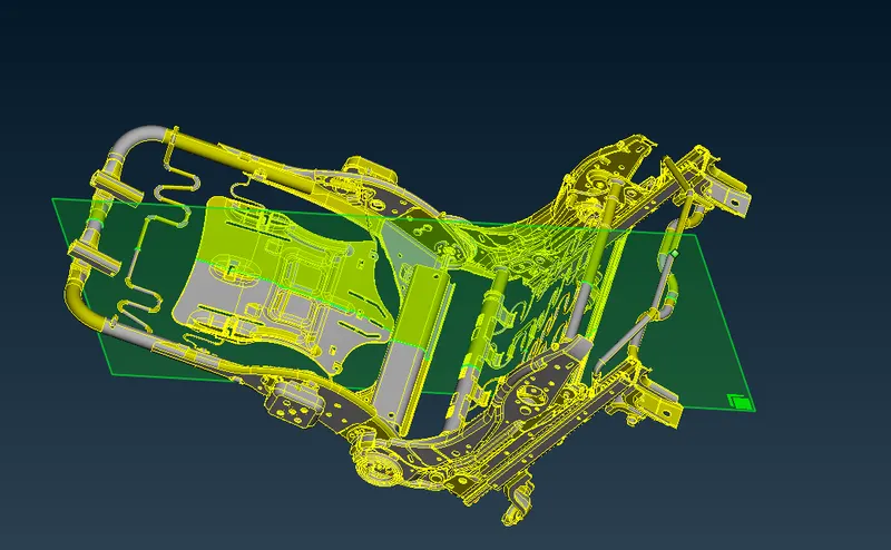
Once choosen the three points properly, Click Middle Mouse Button to which cut exactly at where middle of the component on along Z axis.
Afterthat, we has to manually delete one of the side. Once delete the any one of the side, it's looks like as shown in below image.
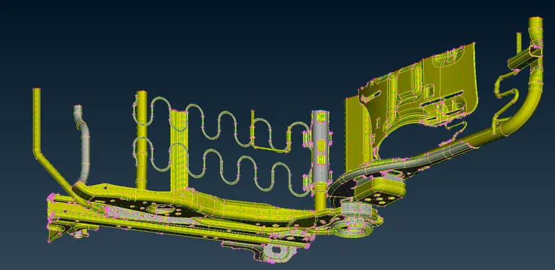
Generally, a middle surface is generating at where exactly on neutral portion of the component. It will helps us to reduce the computational time and then reduce the storage space.
Before going to extracting the middle surface from the parent geometry, Make sure we have to check the geometry Orientation whether it's have proper or not.
Here's above image shows a model has been proper orientation on it. A Yellow Colour indicates a Negative direction and Grey Colour indicates a Positive direction.
Since, a given seat structure model have lots of sub components such as Armrest, Backrest with lumber support, Headset, Seat Base, Seat Track etc..
So, we have to Extract the middle surface by manually in component by component.
Middle Surface Extraction Method :
Automatic Method :
Select the "Middle Surface" option under which "Faces" Sub module & "Topology" module, subsequently choose "Skin" option to which extracting the middle surface from the parent component by itselfs.
Once we proceed to automatic method, ANSA Can automatically extract the middle surface and assigning into the new property card along with providing appropriate thickness to that respective property card.
Manual Method :
First of all, Measure the thickness of the component and then by using "Offset" option to which extract the middle surface for each sub components.
Select the "Offset" Option under which "Faces" Sub Modules & "Topology" main module. Select the faces on any one of the side, make sure keep Feature selection area with the angle of 40 degree.
Click to proceed, provide the half a thickness of the parent thickness and then again click to proceed. Once, a middle surface is extracted, we gonna assigning into respective property Id.
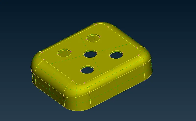
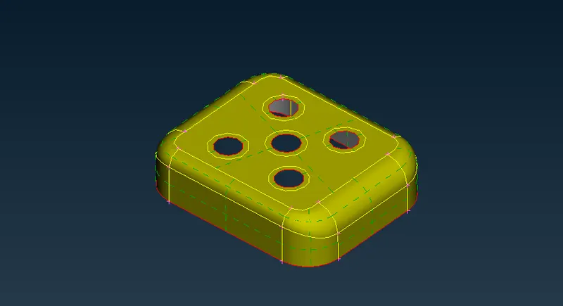
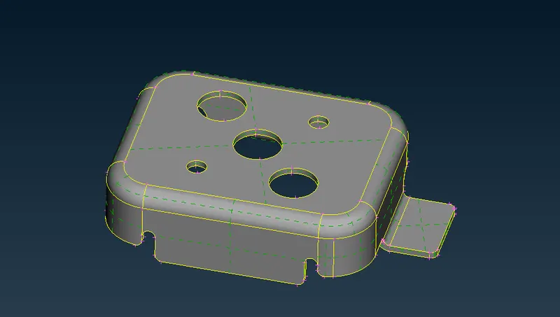
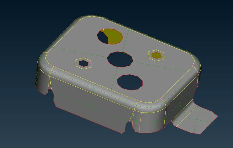
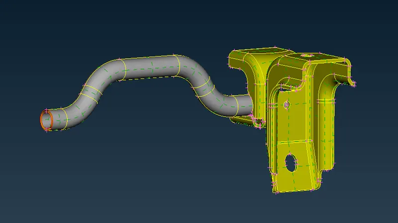
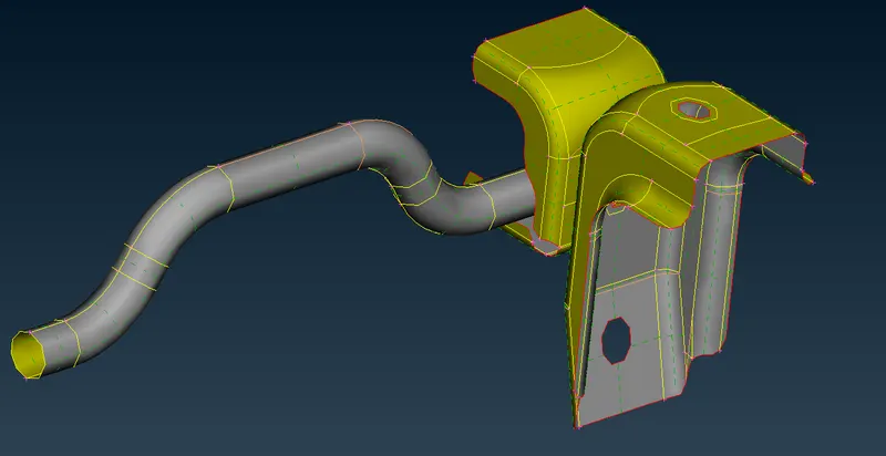
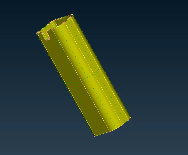
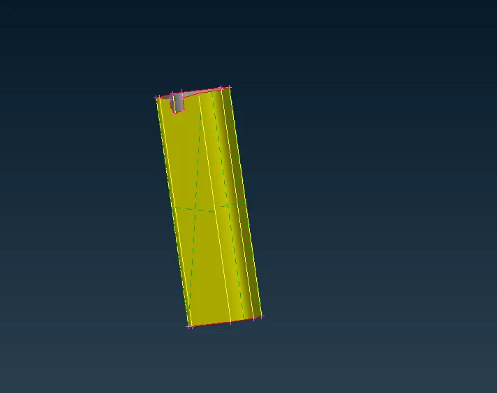
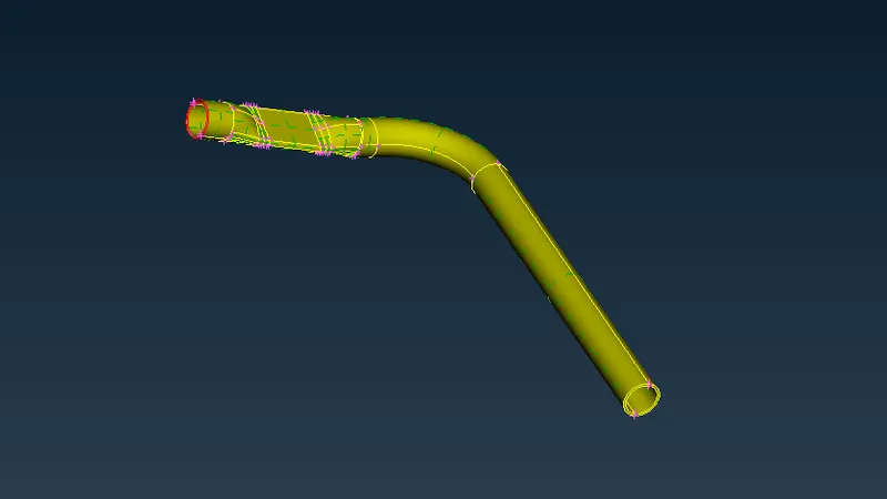
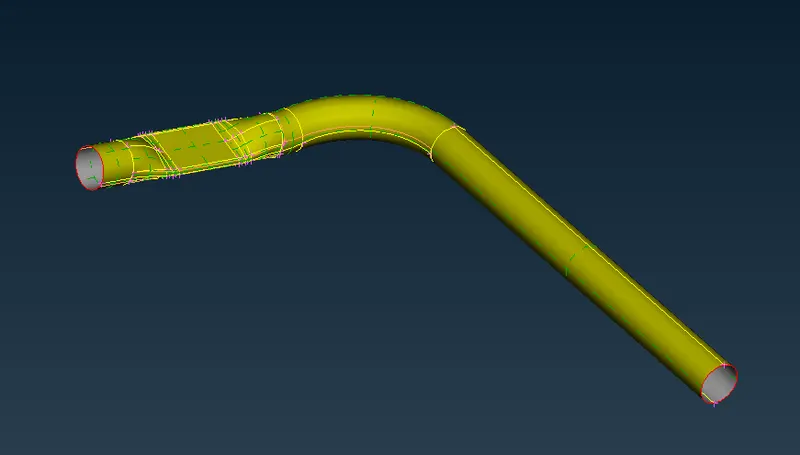
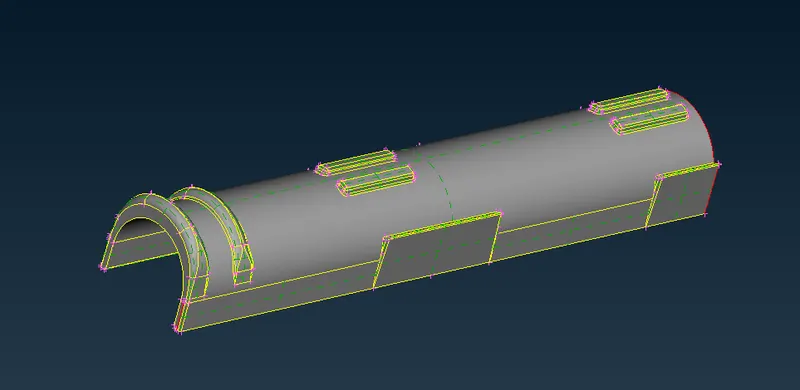
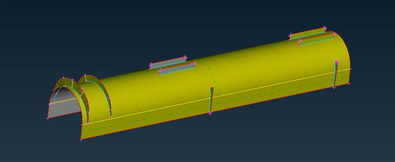
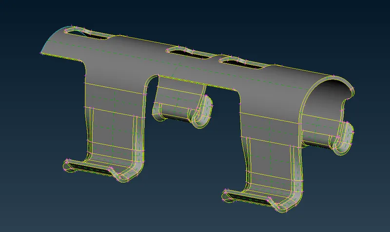
Here's below few images are shown from Parent Geometry to Corrresponding Middle surface.
Arm Rest Bracket Type A :
 '
'
Arm Rest Bracket Type B :
Front Foot Component :
Guide Stay & Head Rest :
Helper Spring :
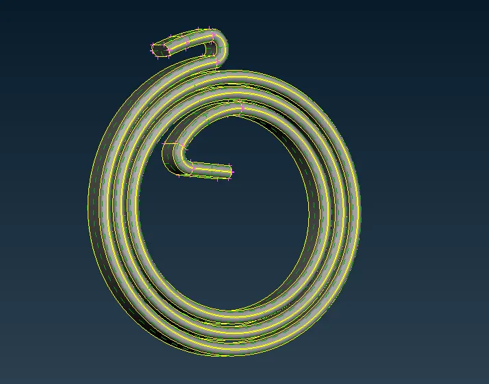
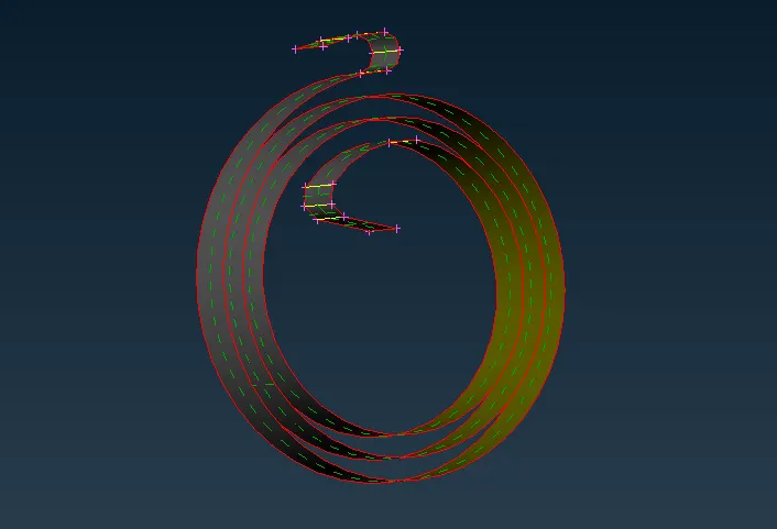
Hook Spring Inner :
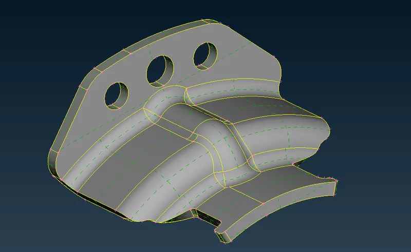
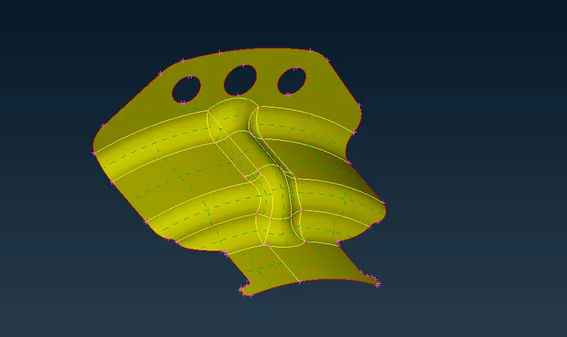
Main Frame :
Member Frame :
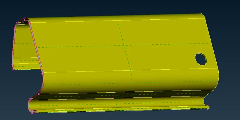
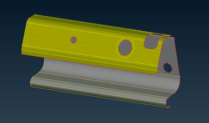
Member Frame Side :
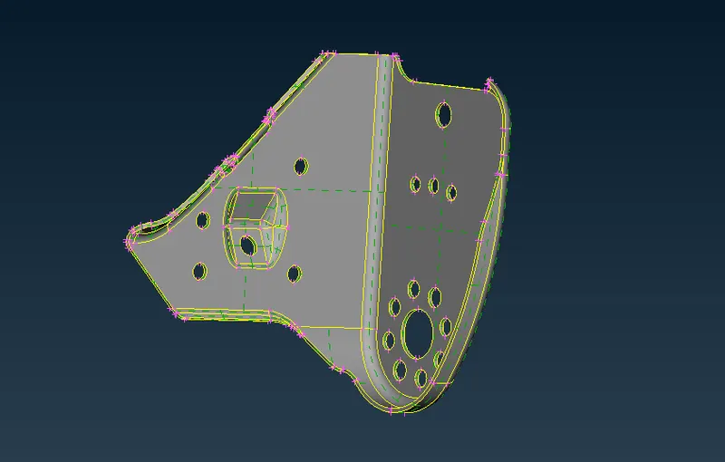
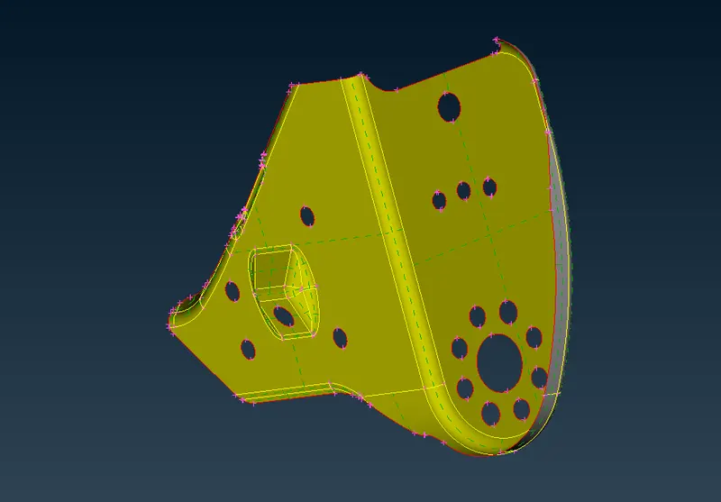
Side Bracket :
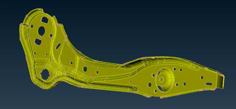
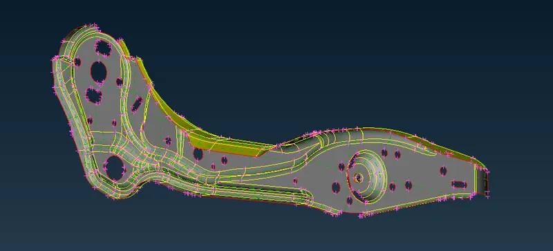
Side Frame :
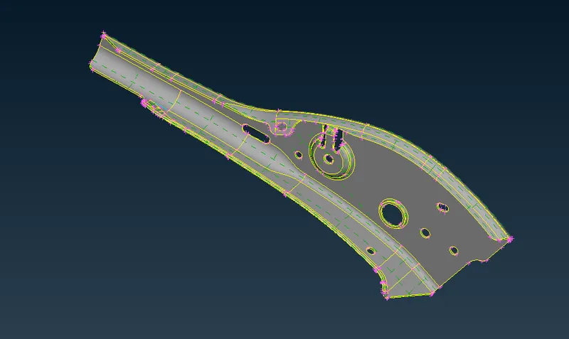
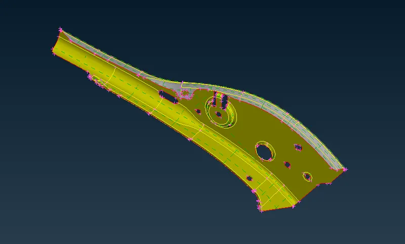
Slide Adjuster Inner :
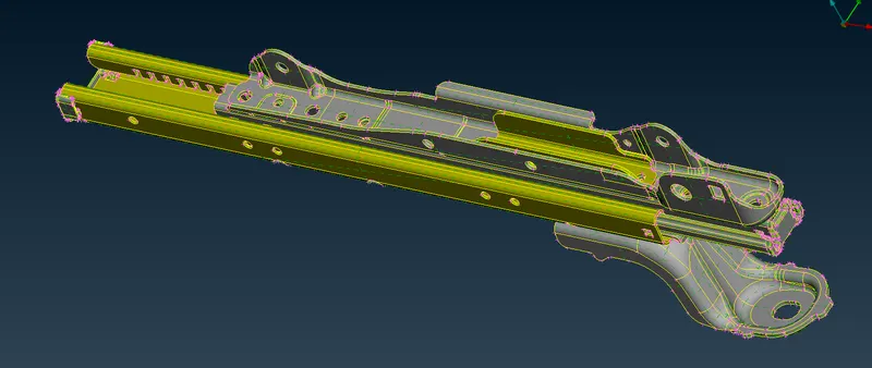
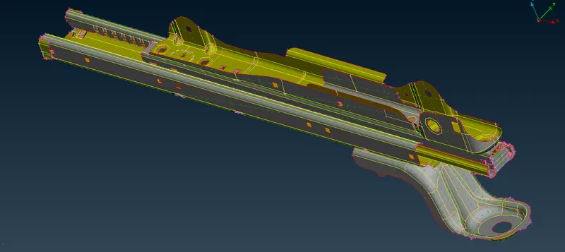
Collar :
Retainer :
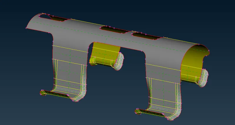
Similarly, we will extract the middle surface for rust of the component.
Complete Middle surfaces for Seat Model :
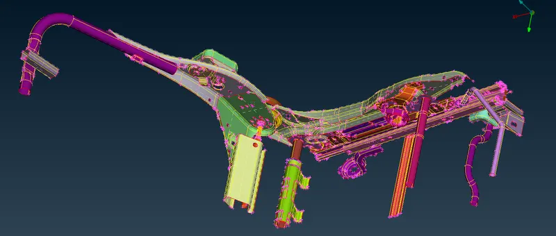
III) Setting the Mesh Parameters and Element Quality Parameters :
In this case, we have to come up with our own Mesh parameters & Element Quality Parameters as based on Size of the sub systems and important feature on lateral distance.
i) Mesh Parameters :
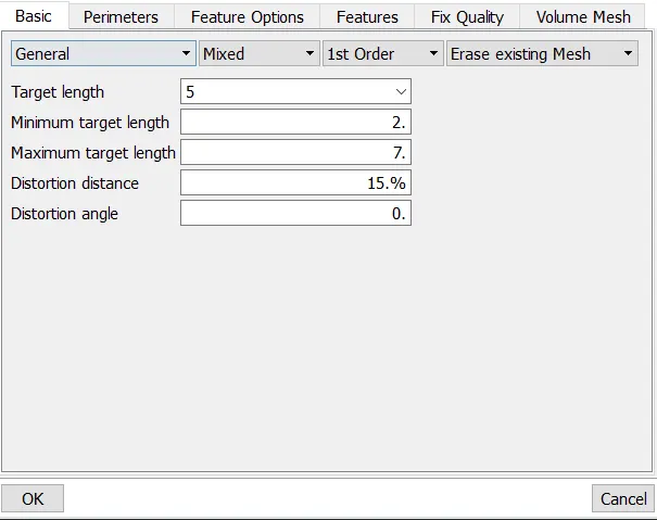
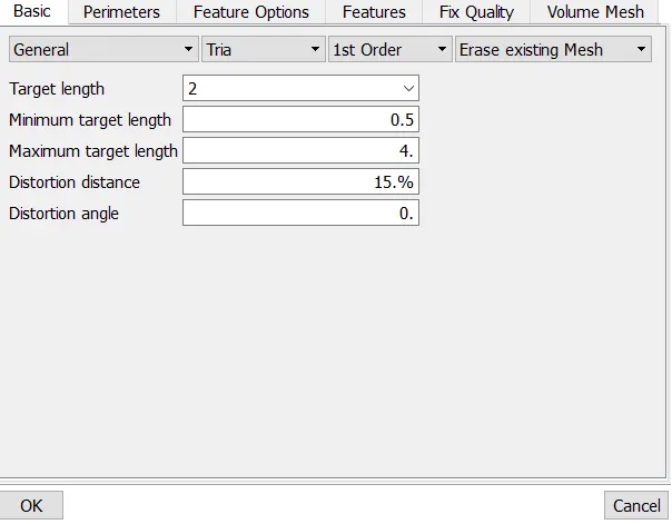
Before going to meshing on the surface, we have to setting the mesh parameters as like shown in the below image.
When we perform meshing operation, initially a basic mesh algorithm has trys to generating the mesh elements as per macros or perimeter node distances.
If we trys to improve the mesh quality by using reconstruct or reshape or Improve option, that time those algorithms are try to recreate the elements according to given mesh parameters even if the macros or perimeters node distance is different.
Mesh Parameters for Mixed Shell Elements on a Mid Surface:
We have to Meshing on a Middle surface with element type of Mixed and Target Element Size of 5 mm.
Mesh Parameters for Trias shell Elements on a Solid Component Surface :
We have to Meshing on a solid component surface with the element type of tria and Target Element Size of 2 mm.
ii) Quality Criterias :
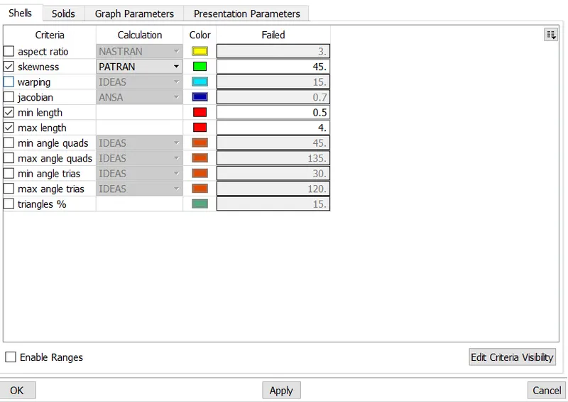
Make Sure we have to enabling all the important Quality Parameters & providing the appropriate values in numerically. It will helps us to checking an failure of the elements while we performing an meshing operation.
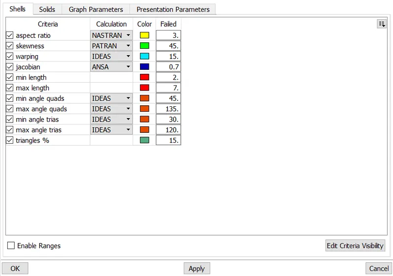
Quality Parameters for Shell Meshing with mixed type of elements :
If we performing an 2D Shell Meshing on a Extracted middle surface. We have to create a elements based on the element qualities which mentioned here below.
Make Sure all created elements should be passed under below mentioned element quality parameters.
Quality Parameters for Shell Meshing with Trias type of elements :
Whenever we generate a 2d shell meshing with type of tria elements alone. We are only consider Skewness, Minimum Element length & Maximum Element Length Criterias.
All Tria Elements should be passing while creating the 2d shell meshing.
Quality Parameters for Tetrahedral Elements :
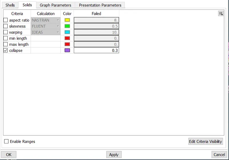
Whenever we generate the Volumetric Mesh with Tetrahedral elements. We have to only consider Tet Collpase Criteria.
IV) Discritization of a Model :
Basically, To divide the entire model into infinitesimal control volume or finite element, that framework is called meshing. This process is called discritization.
1) Performing an shell meshing on the middle surface :
We can performing an meshing by using three different methods. They are
i) Casting Method Meshing
ii) Batch Meshing
iii) Manual Meshing
i) Casting Method Meshing :
A Casting Method is a completely automated method Which generating the Finite Element model from the parent geometry without extracting the middle surface.
Now, We can Implement the casting method on the Back Rest component which is shown in below image.
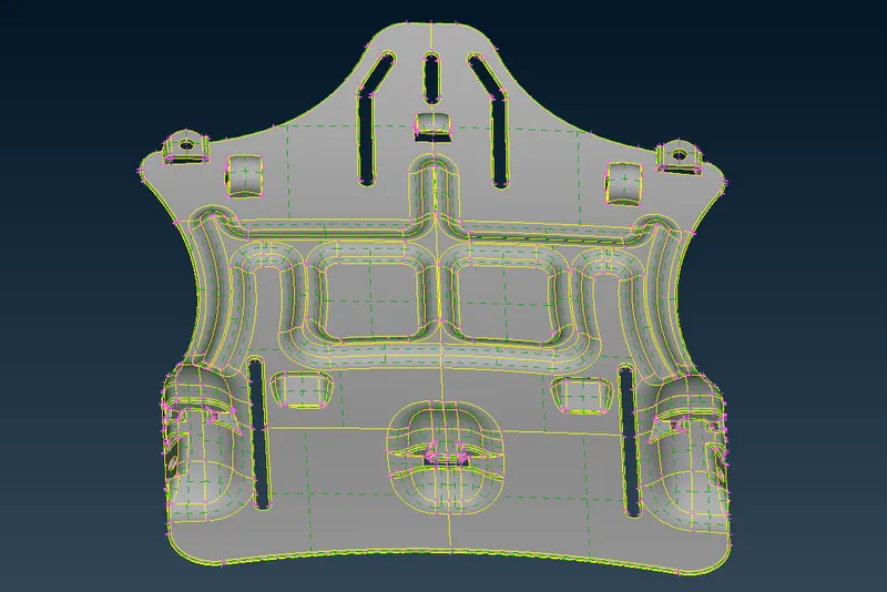
Click the "Mid Surface" Option under where "Faces" Sub Module & "Topology" Module, then followingly select the "Casting" Option.
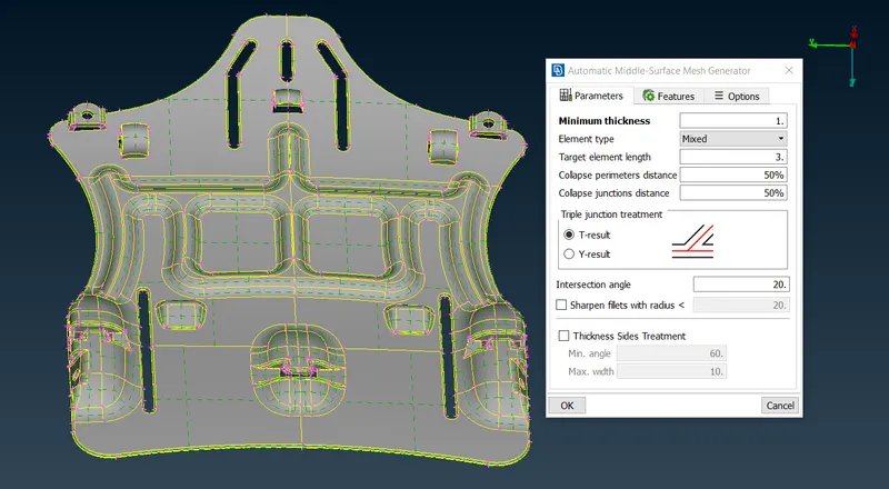
Once Casting Option is selected, subsequently New window to be pop uped as shown in the below image.
Give the Minimum Thickness is 1 mm, Target Element Length is 3 mm, Collapse Perimeter distance & Collapse Junctions Distance is 50 % of target element length distance.
Element Type is Mixed which means, it will meshing with combination of Quads & Trias.
Make Sure hide the all components except Back rest component. Then, click to proceed to which extract the FE Model from the parent Geometry.
It takes very less time to extract the FE Model from the parent component like as shown in below image.
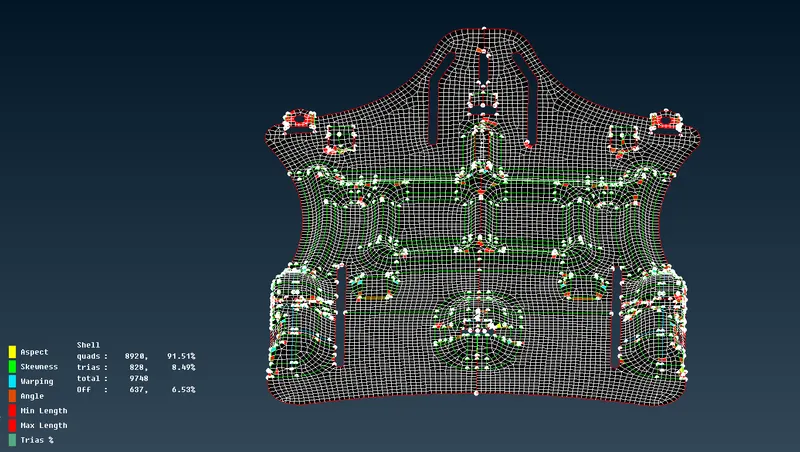
As we can see, there's more number of element are failing and some features are also be not captured properly. So, we have to work on it by manually by using "Align Manager" to which reduce the element failing and also capturing the feature properly.
Capturing Features by Using Align Manager :
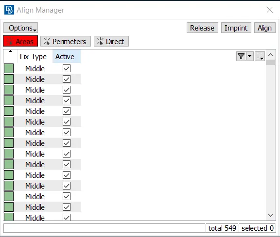
Make Sure keep open the Align Manager while doing any of the process performing on the FE Model.
Once Align Manager tab is opened, it's appeared like as below image.
Feature One :
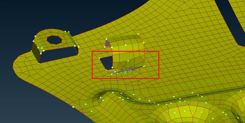
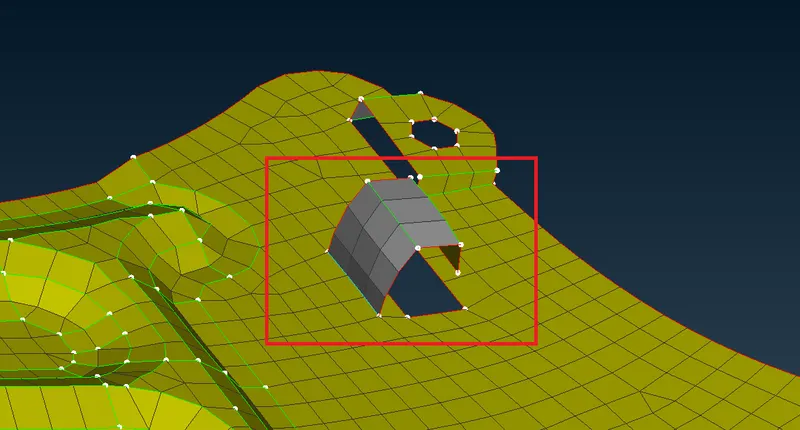
We can see from the first image, a elements are distorted like as shown in the image. A FE model feature should be properly at which exact middle of the parent feature.
First of all, Delete the duplicate elements from where inside the red color box region. And then, Open the "Align Manager" from where "Faces" Sub Module & "Topology" Module.
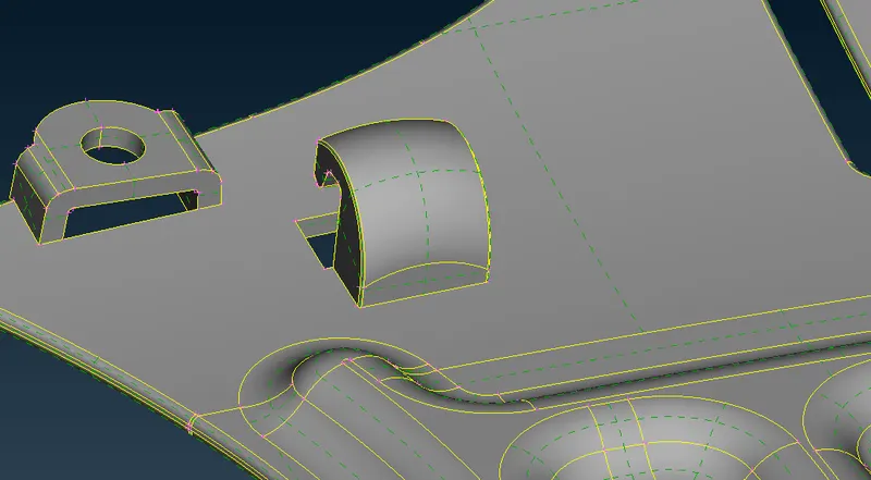
Select the "Areas" Option from the "Align Manager", followingly click & hold on Right mouse button. Then, select the "New With Middle" Option, followingly select the elements which we want to be Align.
Continuosly, click to proceed and then selecting the inner face first & Outer face second in the parent Geometry. Once again, click to proceed.
After done the all steps, finally we got a FE Feature in properly.
Feature Two :
As we can see, here also features are not capturing properly by casting method. So, we have to manually work on it with the help of Align manager.
Similarly, we gonna capture the FE Model at where neutral portion whereever required by using "Areas" option in the Align Manager.
Select the "Direct" Option in the "Align Manager" and make sure enabling the Areas, Axes & Nodes. Subsequently, join the Macros together in proper manner.
Another method is "Join" Option under where "Macros" Sub Module & "Mesh" Module. Make sure keep ON the Align Manager while performing an join process, then only Align Manager option were enabling in the Join Option List.
We have two Option are available which are Merge & Keep Bigger. We can use "Merge" Option while performing on the small macros like fillets and We can use "Keep Bigger" Option while performing on the bigger Macros.
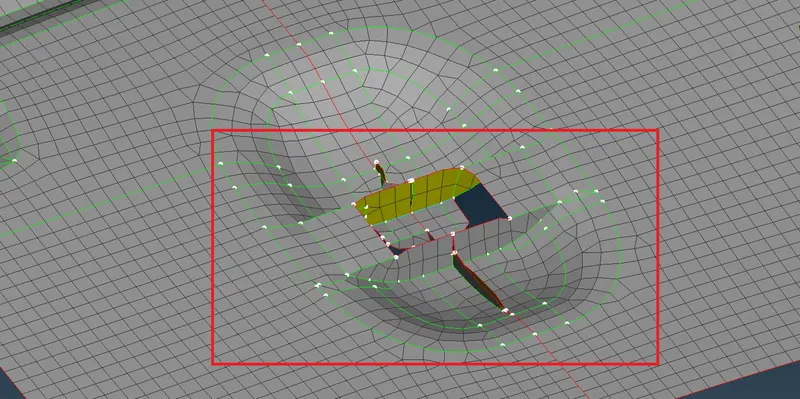
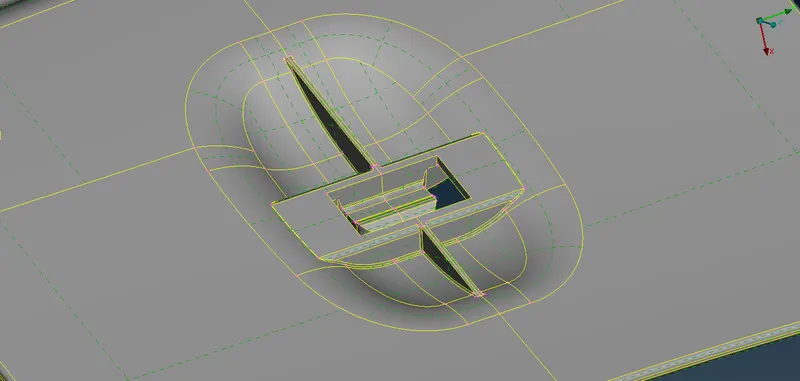
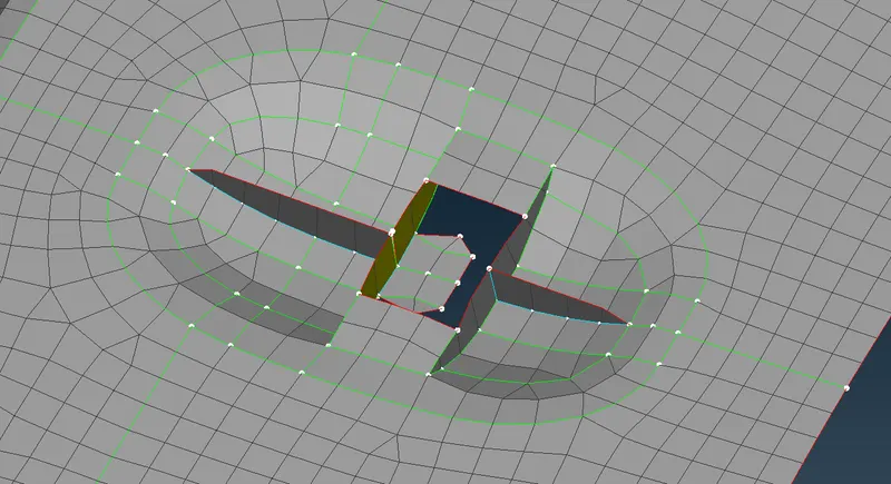
And another method is to select the "Areas" option, click & hold on Right Mouse button to which select the "Add to" sub option. Then, we select the two adjacent surface which we gonna join together.
After done all the process, we got a proper features as shown in the below image.
Feature Three :
Again we use "Areas" option under the Align Manager to which capturing the FE Model at where neutral position as we saw in previuosly.
By Using "Paste" Option to which align the elements properly at where middle.
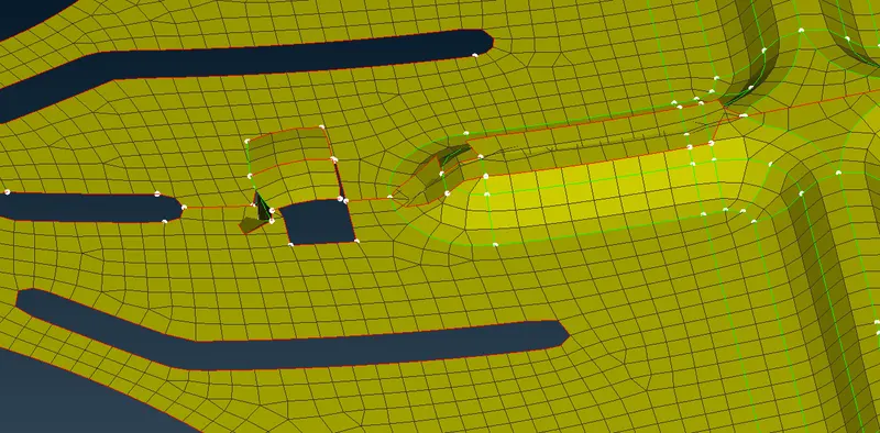
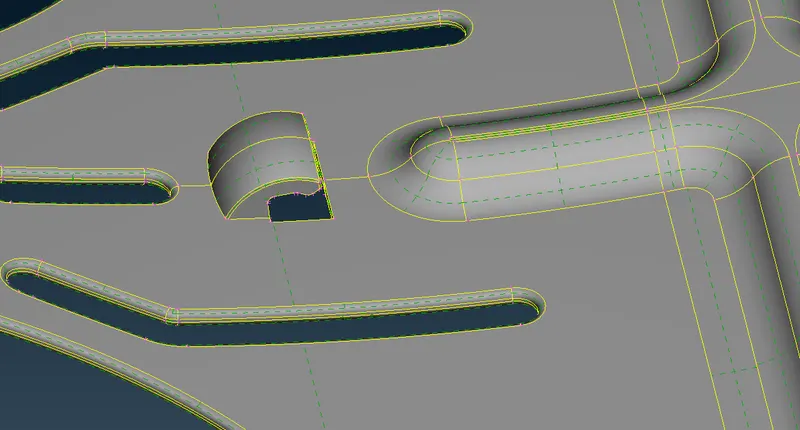
After Done the all process in proper manner with the help of Align Manager, it has looks like as shown in the below image.
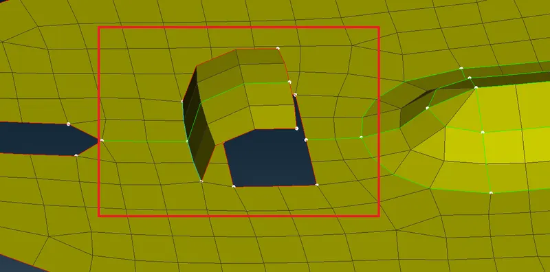
Feature Four :
A feature lines are not capturing properly by Casting Method as like in the parent Geometry.
In this case, we have a option called "Imprint" option which help us to imprint the double cons on the FE Model.
Inorder to Imprint the double cons to the FE Model, Initially we have to select the "Imprint" option from the "Align Manager" and then automatically parent Geometry will be visible. Followingly, select the double cons which we want to imprint on it. And Then click to proceed.
By using paste option which to made a connectivity between the elements.
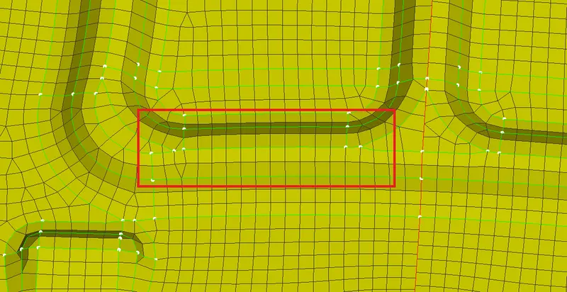
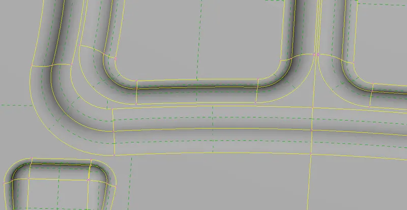
After done the imprint process, we got a proper feature in the FE Model as like in parent component.
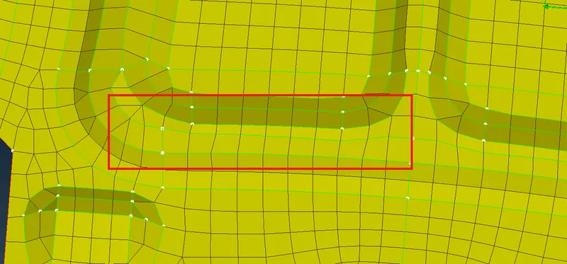
Apart from this, we have to work on manually to eliminate the element failing and getting the proper mesh flow.
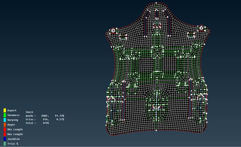
After done all process, we got the proper FE Model for Back Rest Component as shown in below.
ii) Batch Meshing :
A Batch Meshing also a automatic method which has been discritize the surface as per given mesh & Element Quality parameters. But, we have to manually extract the middle surface from the parent component by automatic or manual method.
We have to extract the middle surface for the respective component before gonna perform batch meshing.
Create a new part and assigning the respective component.
Assign the component into the meshing scenerio and click to run.
Retainer :
We had already extracted the middle surface for Retainer component as shown in below image.
After that, create new part in the Model browser, make sure we have to assign the retainer component into new part.
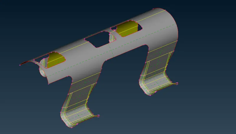
Select the part as a meshing scenerio which we gonna perform batch meshing.
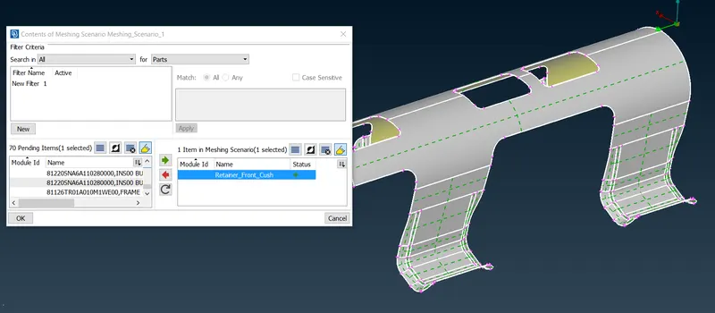
Click the Run option to which perform batch meshing by itself.
After Ran through, we got a these kind of results like as shown in below. A batch meshing is gave result a proper one, but little manual work has been required like avoiding the tria are falling in the edge.
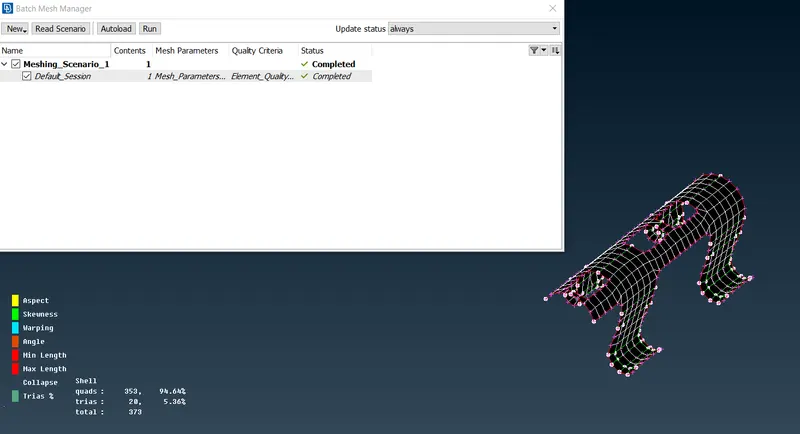
Finally, we got FE Model for Retainer.
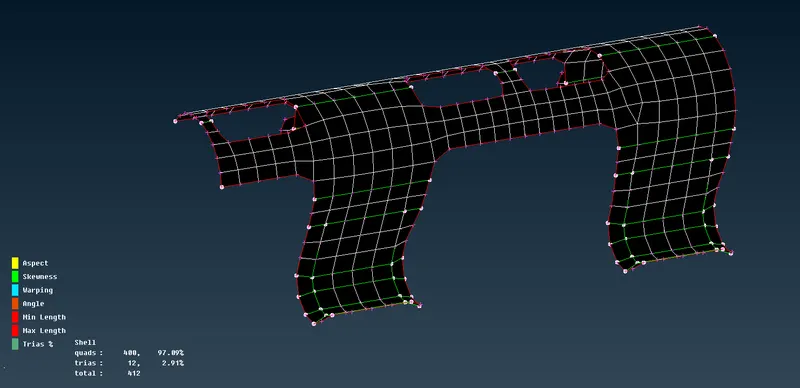
Collar :
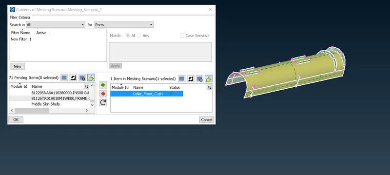
We had already extracted the middle surface for collar component as shown in below image.
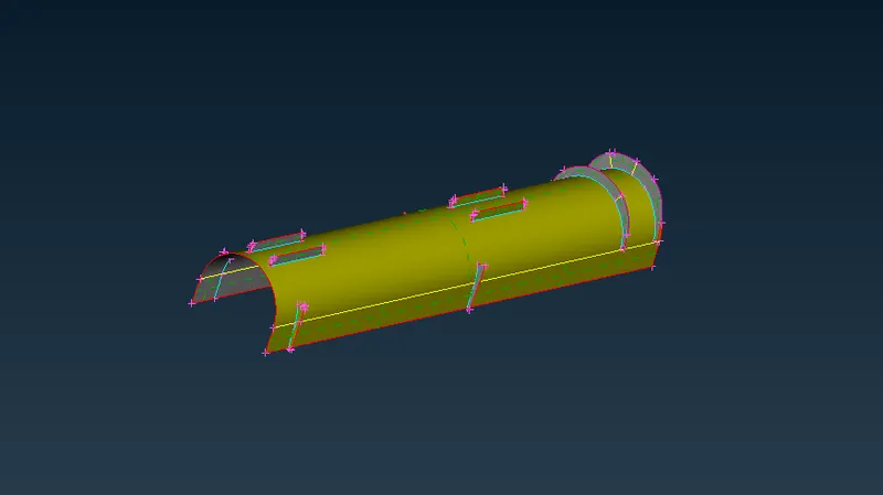
Select the model for meshing scenerio and run it.
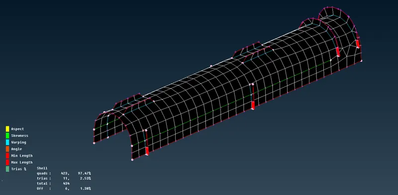
We got results like this as shown in below, a few elements are failing due to minimum element length criteria.
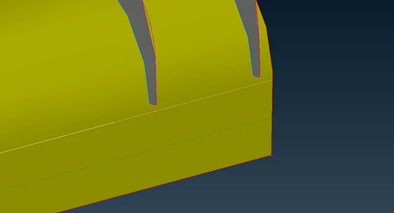
A Batch Meshing had been wrongly defeatured like as shown in below images.
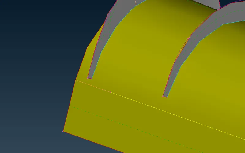
we have to maually work on it like in below image.
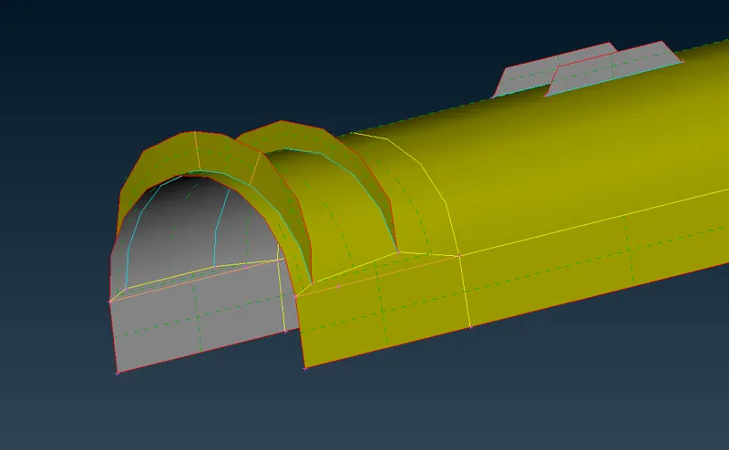
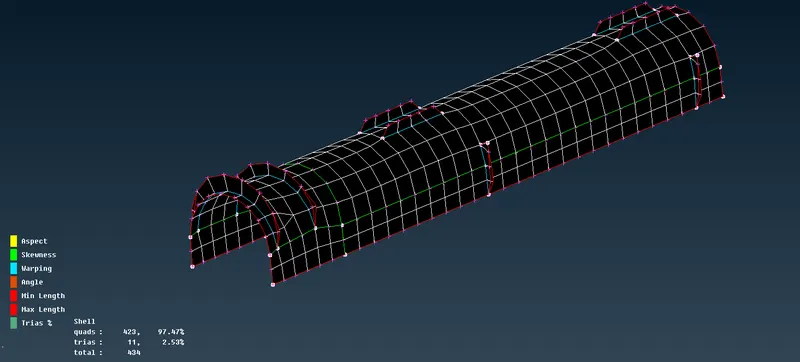
After worked by manually on some few areas, we got a properly flow of mesh and eliminate the elements are failing.
If any component, there's have more features are presented or need to create a washer split around the hole. Better we gonna manual meshing, rather batch meshing.
iii) Manual Meshing :
First of all, Make sure keep the resolution of components to which distance between the two nodes is equal to the target element length by using "Length" option under the "Perimeter" sub module & "Mesh" module.
By using Best or Spot algorithms with Mixed type of elements to which performing the meshing operation on surface by surface along with checking the quality of each & every elements is necessary.
If generated elements are not got proper orientation of flow or any elements has been failed due to any of the given element quality criterias. We have to use reconstruct option or Improve option to which remesh on it, by results we get proper mesh flow orientation of elements and also avoiding the element failing.
If any of the feature lateral distance is less than the minimum element length criterias. Then, We have manually defeaturing out little bit for which avoiding the elements faling due to minimum element length parameters.
Here's below I mentioned few meshed components by manually.
Arm Rest Bracket Type A :
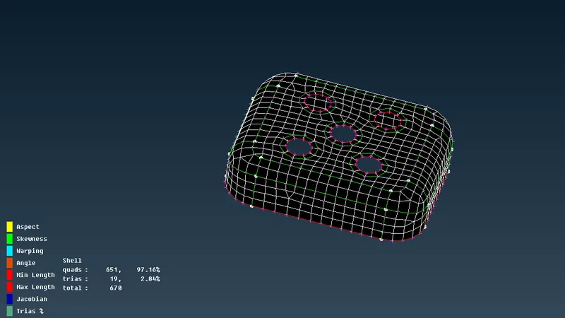
Arm Rest Bracket Type B :
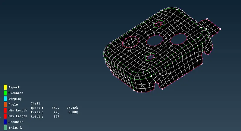
Front Foot Component :
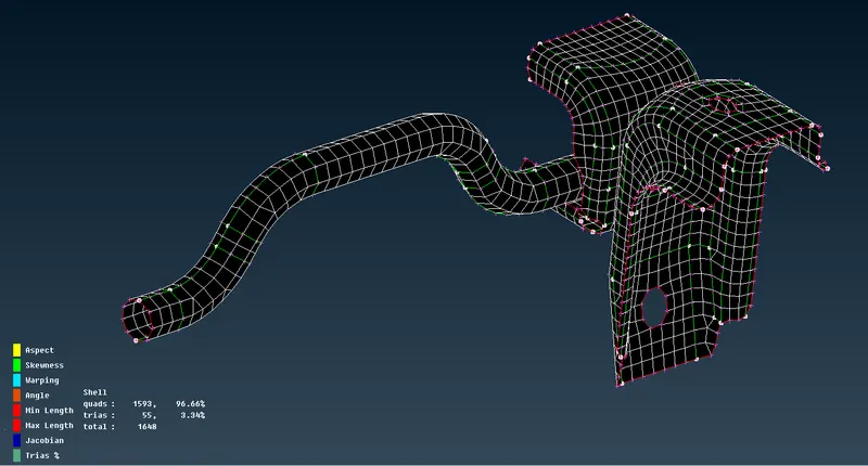
Guide Stay, Head Rest :
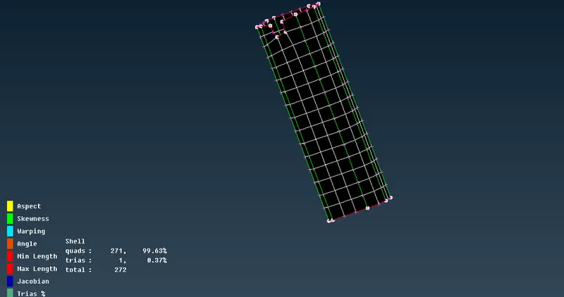
Helper Spring :
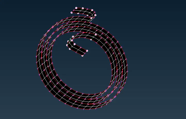
Hook Spring inner :
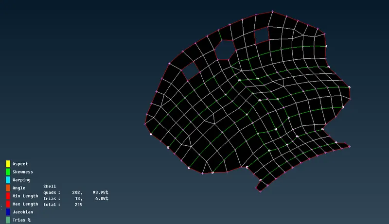
Main Frame :
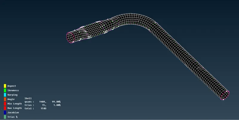
Member Frame :
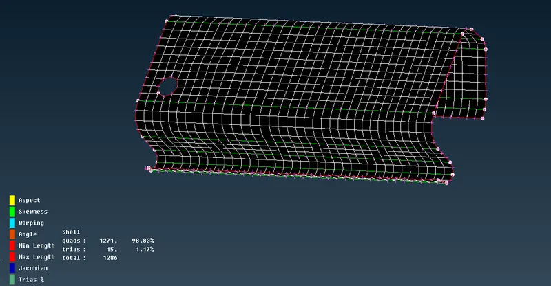
Member Frame Side :
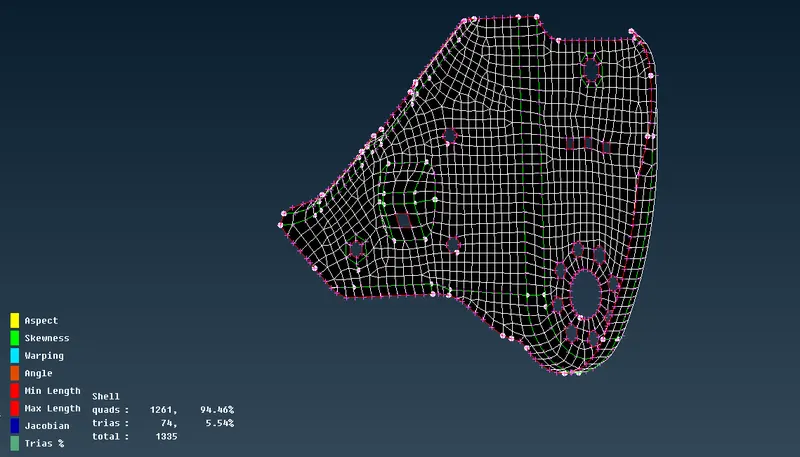
Side Bracket :
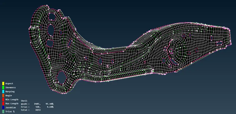
Side Frame :
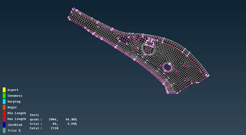
Silde Adjuster Inner :
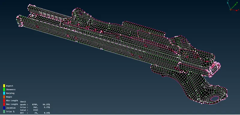
In few components, some few elements are failing for minimum element length criteria. This failure is occured due to triple cons & also macros are size very less.
If Minimum element length issue are presented in the FE model. By results, simulation time is increased.
2) Performing shell meshing on the Surface :
Inorder to perform volumetric meshing with tetrahedral elements, we have to create a shell meshing with tria type of elements.
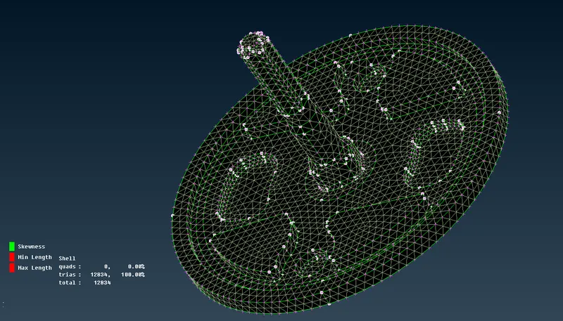
We have to meshing on the solid component surface which as shown in below.
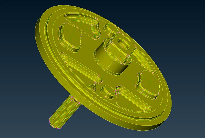
By using Best or Spot algorthims option with tria type of elements to which performing an meshing operation on a surface of the solid component.
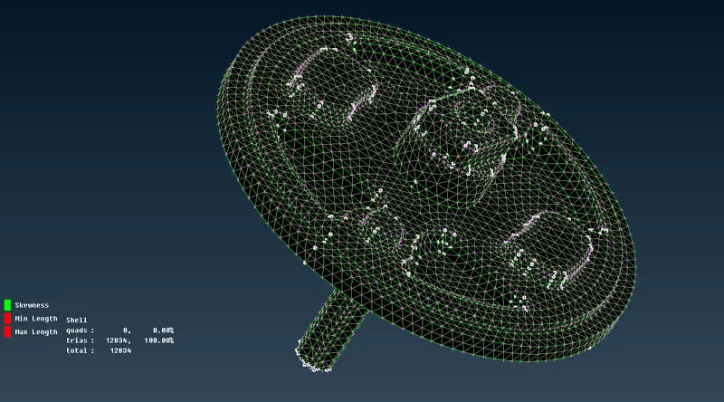
Shell elements should be creating as per mesh parameters & element quality parameters.
All created elements are passing the element quality parameters. After done the shell meshing, it's looks like as shown in below image.
V) Defining the Control Volume :
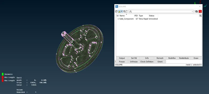
Before going to create a volume meshing, make sure we have to defining the volume region for which generating the 3d tetrahedral elements on interior of the shell elements..
Make sure, we had been done the 2d shell element properly without any opening. Then only, we have to define the volume.
After defining the volume to the solid component, it has been shown up in the list like as shown in below image.
We can choose the type of algorithm which is Tetra Rapid. It have Unique growth rate for generate the volumetric elements on interior of the volume.
VI) Performing an Volumetric Mehsing :
Inorder to generate the tetrahedral element , make sure we had to defined the volume for which generating the volumetric mesh.
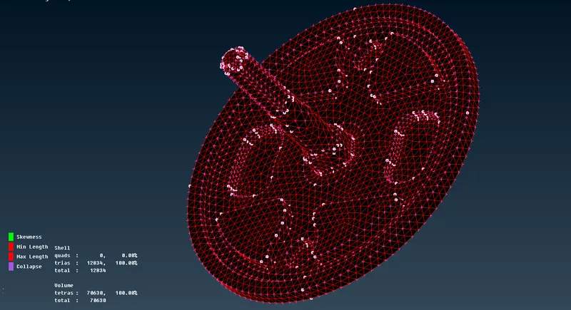
Select type of algorithm which is Tetra Rapid in this case and then Click to generating the volumetric mesh.
Once done the Volumetric meshing on the components, it will looks like as shown in below image.
Also, we have to check the Tet collapse error from the Volumetric elements. Here, there's no elements are failing due to tet collapse.
VII) 1D Element Representation :
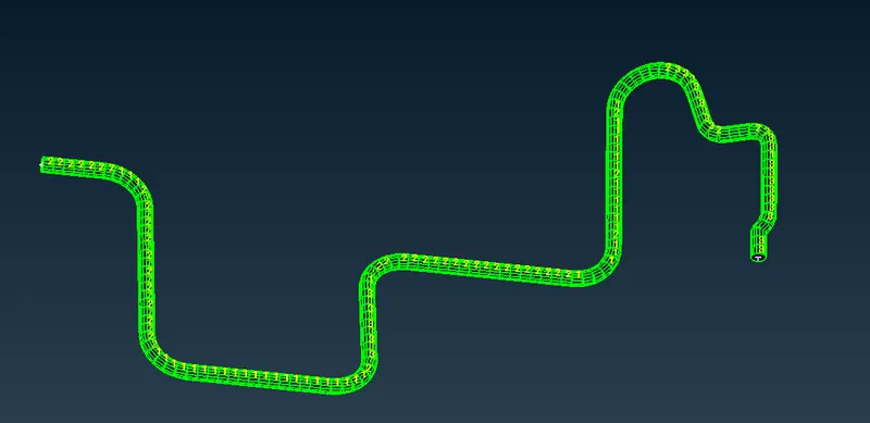
We have to represents the closed coil spring by uisng CBAR or CBEAM 1D Elements
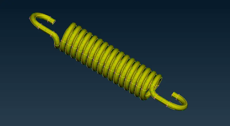
Inorder to represents the CBAR element, we have to create a middle curve for a coil spring at where neutral axis by using " Middle Curve" option under where " Curves" Sub module and "Topology" module.
After creating the middle curve, it will looks like as below image.
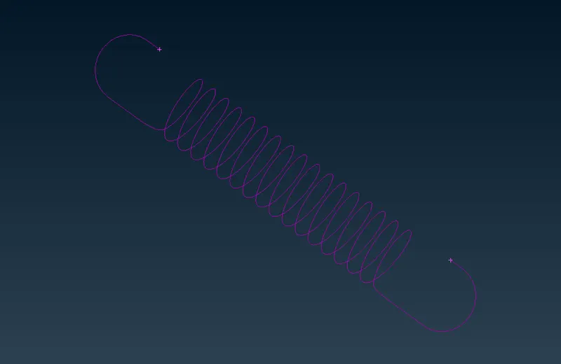
Followingly we have to creating the COG Point for that Curve by using "COG" Option under where "Points" sub module and "Topo" module.
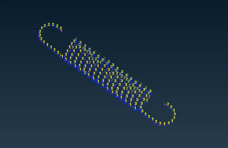
Select the "CBAR" Option, followingly check "Orientation with nodes" & keep Curves.
Subsequently, select the Curve & COG point and provide the element size which is 3 for this case. Create a New Property card and then provide the appropriate Cross sectional radius of the coil spring.
Once we provided the radius, it will automatically calculated the cross sectional area, minimum & maximum moment of inertia and also Polar moment of inertia by using diameter which we given.
Once, we created the 1D CBAR Element, it will looks like as shown in the below image.
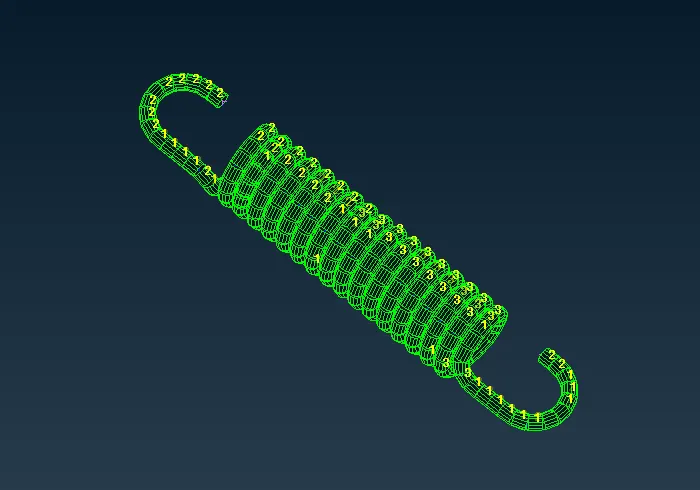
Inorder to see like a element, we have to enable "As Solids" under "Line Element Cross Section" at presentation Parameters. After done, it will looks like as shown in the below image.
This is How we represents the Closed Coil spring while we modelling foor analysis.
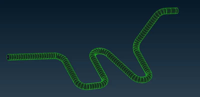
Apart from Closed Coil Spring, Whenever the Circular Cross Section of the component and its properties is constant and also symmetrical in shape, we can use CBAR Or CBEAM 1D Element as which represents on those component.
Similarly, we will represents those components by using CBAR and CBEAM 1D Elements.
Cross Frame :
Thorax Frame :
VIII) Connections :
A Seat Structure is made up of several sub systems, if we weren't made a connections between the sub systems. A Applied load hasn't been transfer from one part to another part.
So, a connections are very important while performing an simulation.
A Raw data for connection is given from design team, we have to make a appropriate connections between the sub systems according to the given raw data.
In this seat model, we have to make a two different connections which are Bolt, Seam Connections.
i) Bolt Connections :
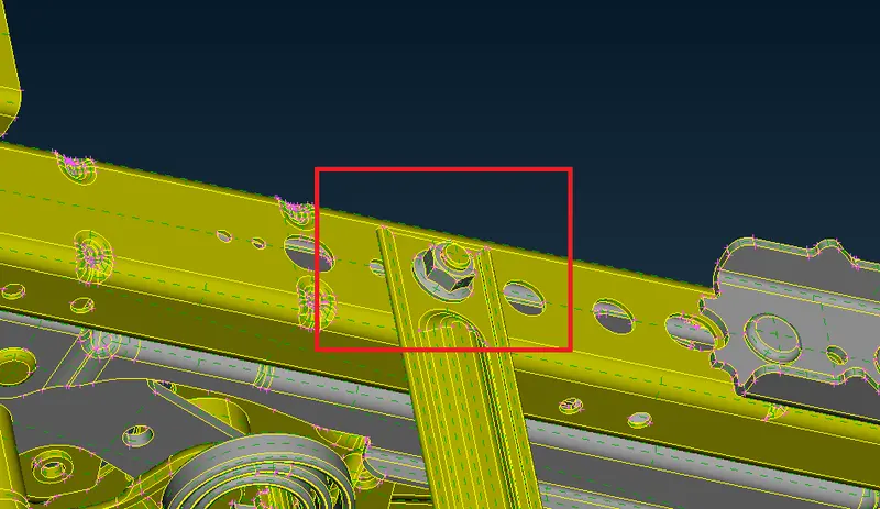
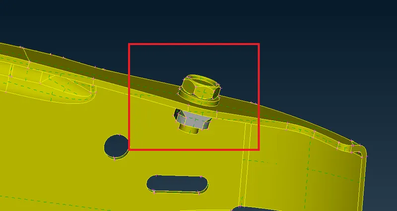
Inorder to represents the Bolts or Rivets in the seat model for NVH Analysis. Usually, a Bolts or Rivet are acts as a rigid structure while analysis a model. So, We have to use RBE2 1D Elements, because it's have more Stiffness like as rigid body.
We have a proper raw data for identifying whereever we have to deploying the RBE2 1D elements for which represents the bolt & rivet in the Finite Element Model.
A RBE 2 is stands for Rigid Body Element type 2, Inorder to create the RBE2 Elements, we have to select the RBE2 option under which "Nastran deck" module & "Elements" sub modules.
Make Sure we had been create a washer split around the hole and also quad elements only should be there.
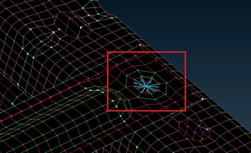
We have a two option to which represents the bolt or rivet connection. First method is cluster type representation, to select the elements which are comes inside the washer split on both sub parts and then click to proceed. Finally, we got the RBE2 Element by cluster method like as shown in below. It have only one independent node which is Master Node and it's have many number of dependent node which are Slave nodes.
Another type of representation is Many Node & Two Node RBE2, to select the elements which are comes inside the washer split and click to proceed. Followingly, we have to do similar process on another sub system which gonna connect together. By Using Two node RBE2 element to which connect between the two master nodes.
Here's below few image which has shown How we represents the Bolt or rivet joints in the Seat model.
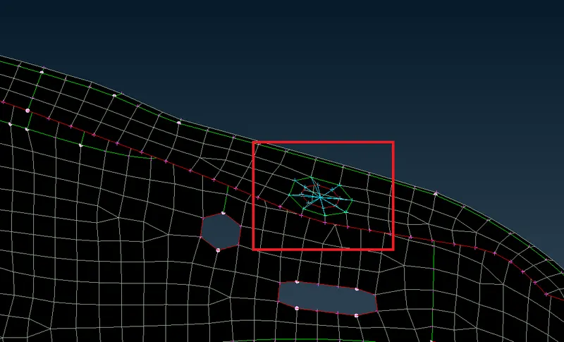
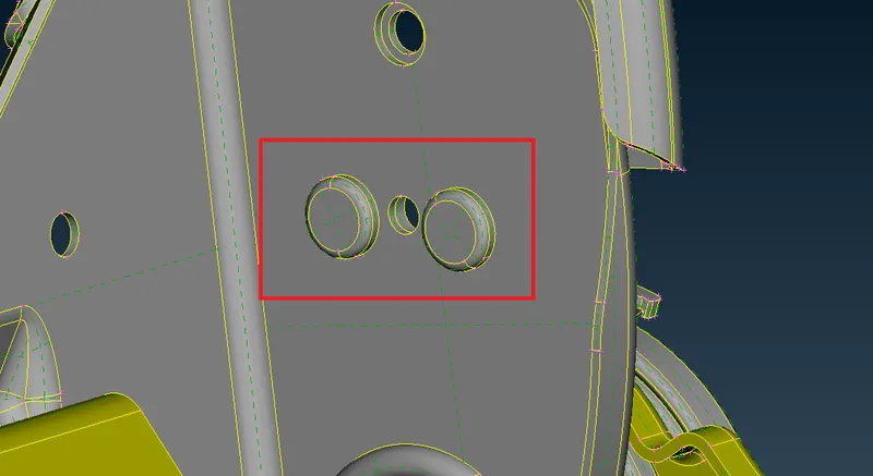
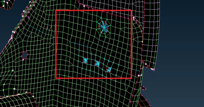
Apart from this, we have to represents the bolt & Rivet connection on whereever required in the seat structure model like how we did in previously.
Seam Connections :
In this case, we gonna a create a seam weld between the sub component with the help of Finite Elements and it's act as a rigid.
By Using Raw data which had given from design team, we will create a seam weld connection on whereever required in the seat structure frame.
First of all, measure the length from the raw material. Extract the Curve by using "Feature2Curve" option under where "Mesh" module & "Perimeter" Sub module.
Subsequently, Converting from curves to seam line by using convert gui option.
Click the connector manager, immediately one tab has been pop up which is "Connection Selection Assistant" and then followingly select the seam line which we going to perform and press middle mouse buttom to get open a new connection manager tab.
Select the parts properly and then If Our connection representation have been parallel to each other, then we going to select the "OVER LAP SHELL" option as a FE Representation. If Our Connection representation have been Perpendicular to each other, then we going to select the "Y - Joint Shell" option instead of "Over Lap Shell" like as shown in below.
Followingly, we have to provide the search distance and setting like as shown in below and click to realize.
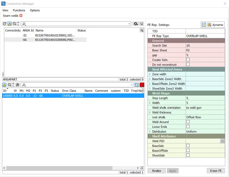
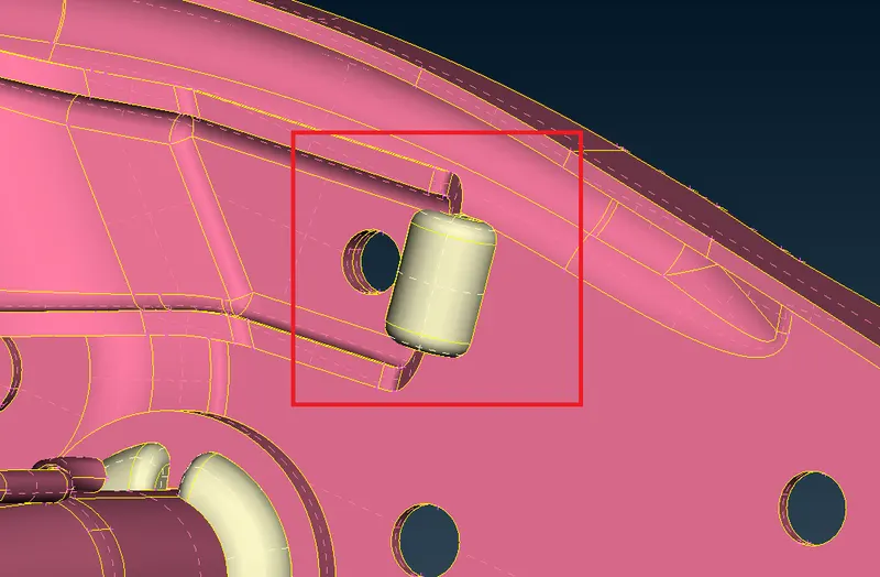
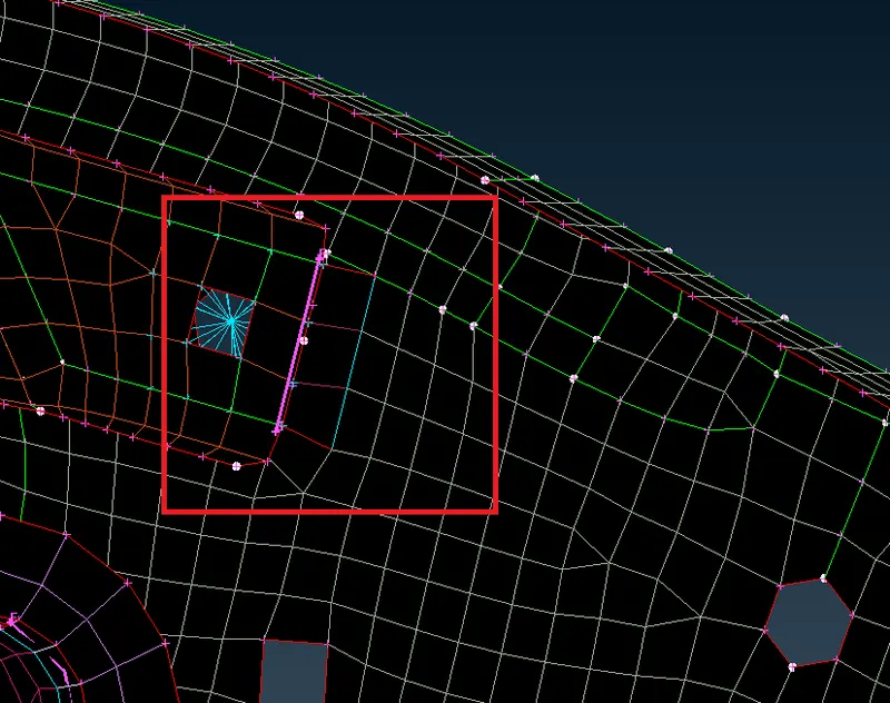
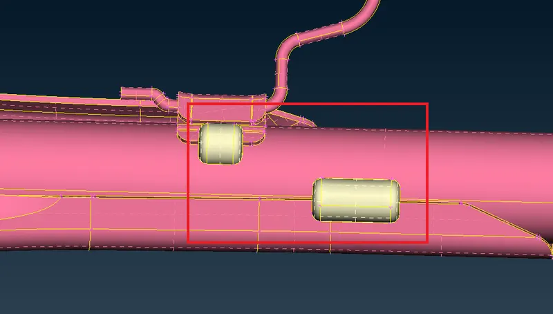
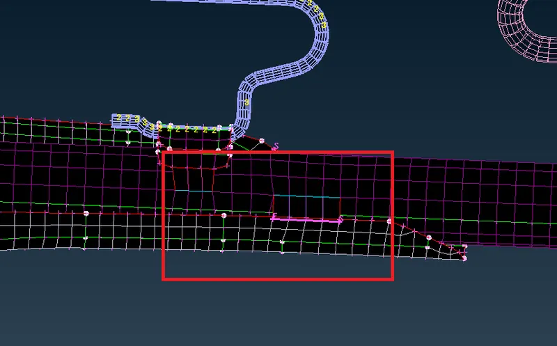
After realizing the seam connection between the sub components, it's looks like as shown in below images.
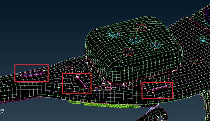
Apart from this, we have to represents the Seam connection on whereever required in the seat structure model like how we did in previously.
CONCLUSION :
Successfully done the Preprocessing on the Automotive Seat Structure frame like Geometry Cleanuping, Middle surface extraction if thickness is less than 5 mm, Meshing with Mixed type of elements on the middle surface, Meshing with tria type of elements on the solid component surface, Defining the Volume for Volumetric meshing, Meshing with tetrahedral elements and then deploying the connection according to the given raw data.
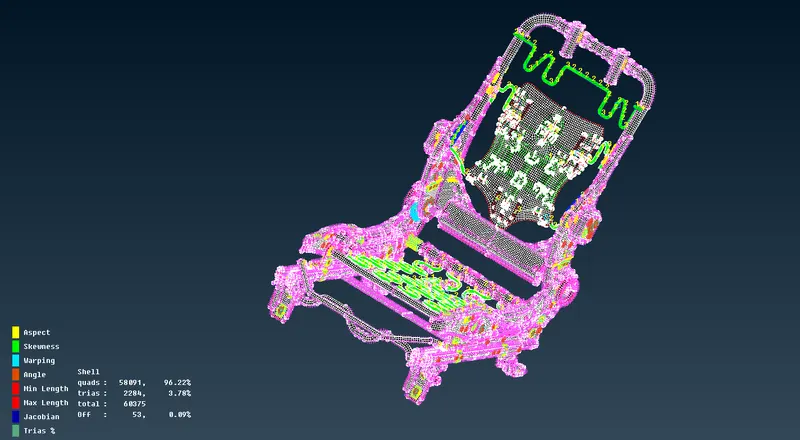
Enabling with Draw Shell as Solids :