Modelling of 25 storey building with the specified properties using ETABS
6. AIM:-MODELLING A 25 STOREY BUILDING IN ETABS.
DATA:-
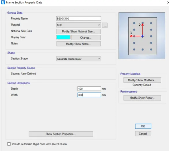
Beam Size= (300 X 400) mm.
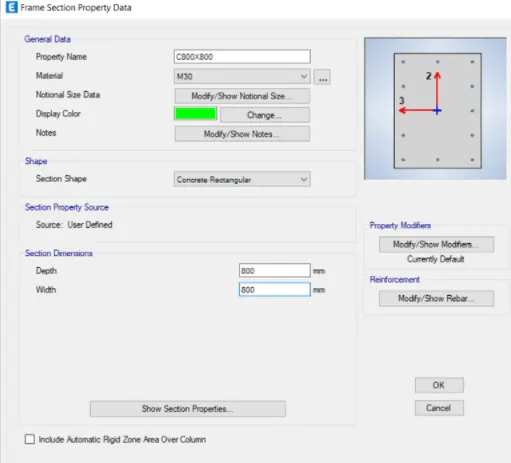
Column Size=(800 X 800) mm. .
Slab Thickness= 150 mm.
Height of storey= 3m.
Height of plinth= 1.5m.
STEPS
STEP-1
Open ETABS 2019.
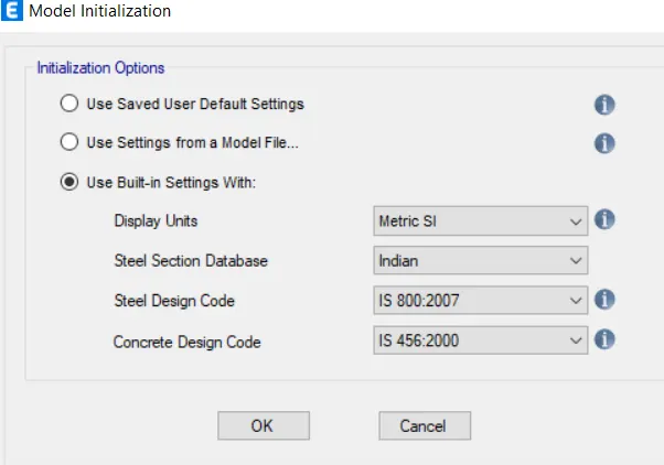
Go to file menu and select new model, a pop up window of model initialization will be opening
Select use built in settings.
Select display units as Metric SI, Steel section data base as Indian, Steel design code as IS 800 2007, concrete design code as IS 456:2000.
Select OK.
STEP-2
A new window of new model quick templates will be appearing.
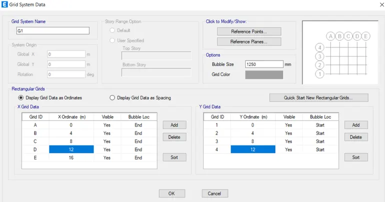
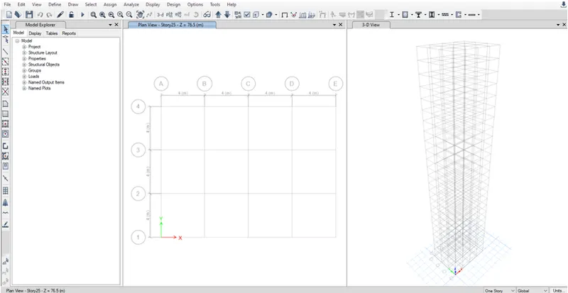
Select the grids and customise grids.
Set X grid data at spacing of 4m, and number of grids is 5.
Set Y grid data at spacing of 4m, and number of grids is 4.
Click OK.
STEP-3
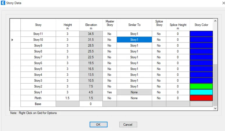
Now select the option custom story data and select edit storey data.
Select plinth height as 1.5m, and height of storey as 3m.
Add storey and make total number of story as 25.
Keep master storey 1 as yes.
Click OK.
STEP-4
Defining the properties of elements.
Go to define and select material properties.
Select grade of concrete as M30.
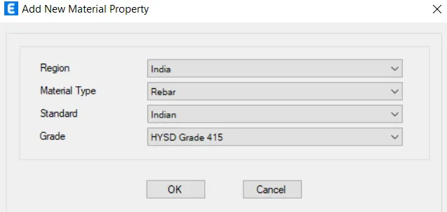
Select steel as HYSD 500and HYSD 415 steel.
PROPERTY OF CONCRETE.
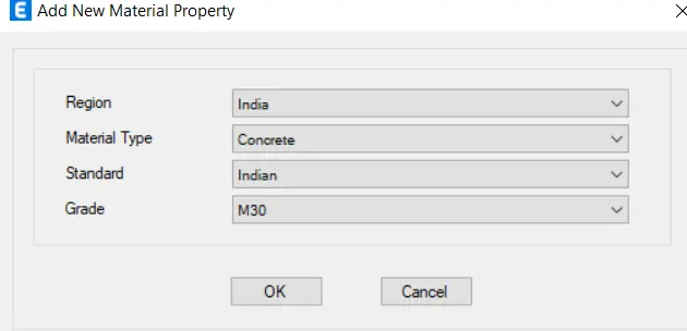
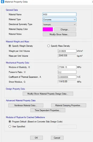
CONCRETE MATERIAL PROPERTY DATA.
PROPERTY OF STEEL.
STEP-5
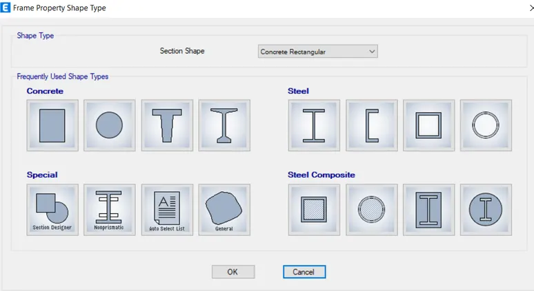
Defining beam column properties.
Go to define tab, section properties and frame sections.
FRAME PROPERTY TAB.
BEAM DETAILS.
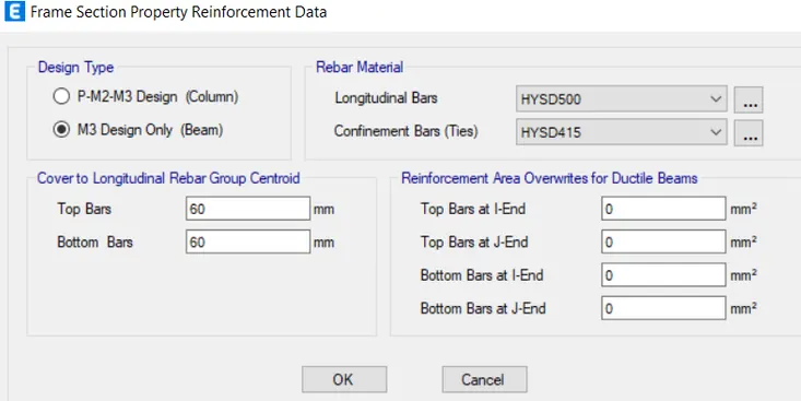
BEAM REINFORCEMENT DETAILS.
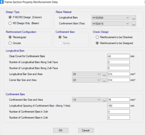
COLUMN DETAILS.
COLUMN REINFORCEMENT DETAILS.
STEP-6
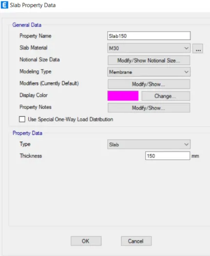
Defining slab properties.
Go to define tab, section properties and slab sections.
SLAB PROPERTY DATA.
STEP-7
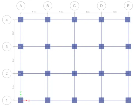
Drawing of beams and columns.
In the left side of the draw panel select the option quick draw column.
Place columns on the grids.
For drawing of beams select the option quick draw beams in the draw panel and place the beams.
DRAWING OF BEAM AND COLUMN.
STEP-8
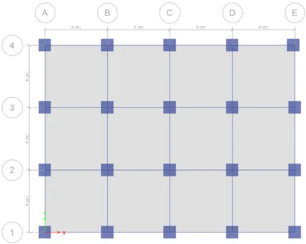
Drawing of slab.
In the left side of the draw panel select the option quick draw floor.
Place slabs between the grids.
STEP-9
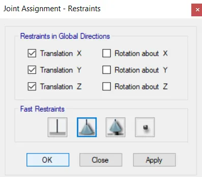
Change the base connections.
Go to the base view in the plan.
Select the base view.
Select assign tab, joints, restraints and select pinned connection.
JOIN ASSESSMENT DETAIL.
STEP-10
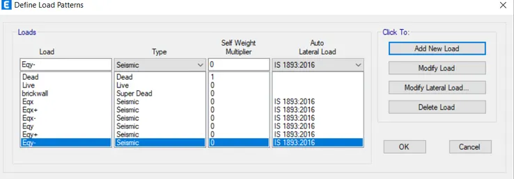
Assigning loads on the structure.
Select define, load patterns and enter the load patterns as shown in the image.
DEFINING LOAD PATTERNS.
STEP-11
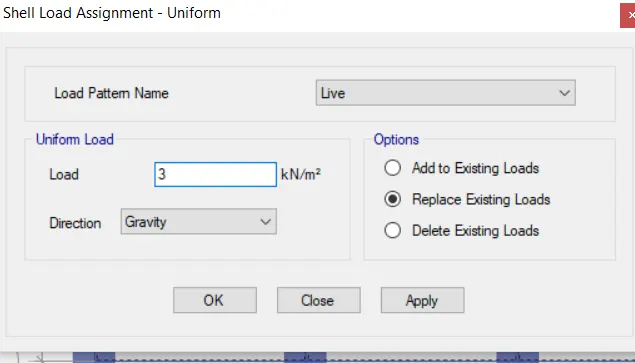
Assigning live loads.
Go to assign tab and select shell loads, uniform and assign load of 3KN/M^2.
STEP-12
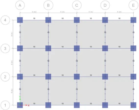
Assigning load on beam as brick wall load.
Apply load of 10KN/M.
BRICK WALL LOAD PATTERN TYPE.
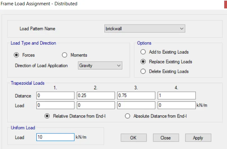
BRICK WALL LOAD APPLIED ON BEAMS.
STEP-13
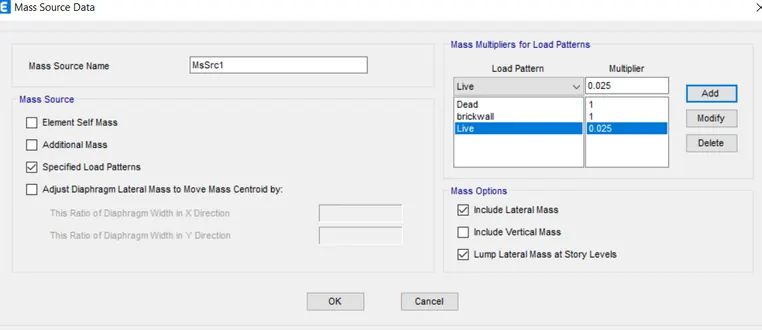
Assigning mass source to model.
Go to define tab select mass source and enter the details as shown in the image.
MASS SOURCE DATA.
STEP-14
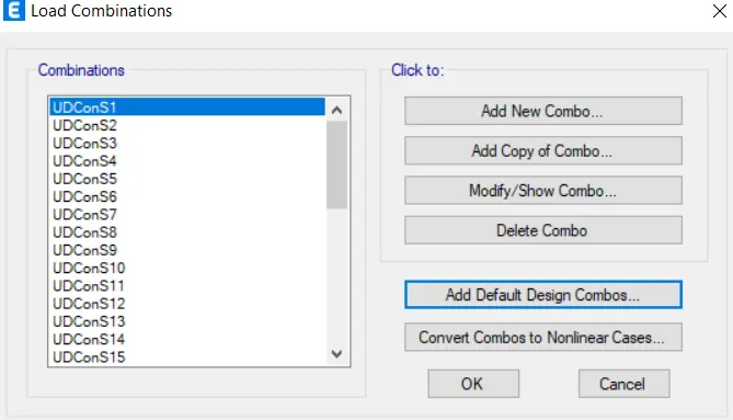
Generating load combinations.
Select define tab- load combinations- add default- concrete frame-convert to editable.
LOAD COMBINATION DATA.
STEP-15
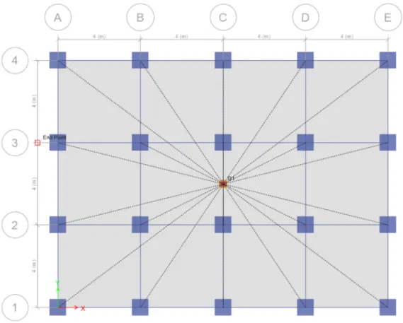
Assigning diaphragms to the model.
Go to assign tab select shell, select diaphragms and select D1.
Apply the diaphragms.
STEP-16
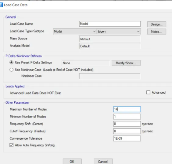
Creating modal analysis.
Go to define tab-modal cases- modify.
Enter the data as shown in the image.
STEP-17
Checking the model.
Go to the analyse tab and select option check model.

STEP-18
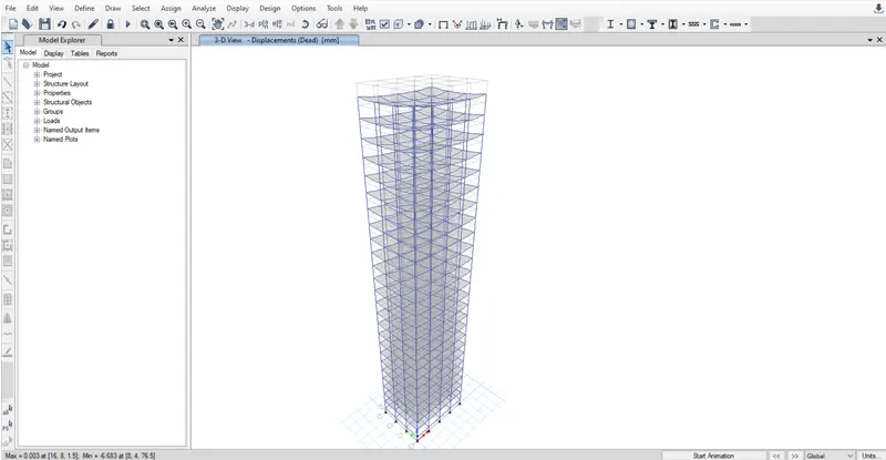
Running the analysis.
AFTER RUNNING THE ANALYSIS.
STEP-19
Modal results.
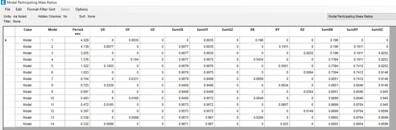
Select display-show tables- structure output - modal information-modal participation mass ratios.
A table will be appearing on the screen.