Modelling of 25 storey building with the specified properties using ETABS
ANSWER:-
Aim:- To model a 25 storey building with the given structural properties using etabs 2018.
Introduction:-
- ETABS is an engineering software product that caters to multi-story building analysis and design.
- Modeling tools and templates, code-based load prescriptions, analysis methods and solution techniques, all coordinate with the grid-like geometry unique to this class of structure.
- Basic or advanced systems under static or dynamic conditions may be evaluated using ETABS
- ETABS modeling is the generalization that multi-story buildings typically consist of identical or similar floor plans that repeat in the vertical direction.
- Modeling features that streamline analytical-model generation, and simulate advanced seismic systems.
- Once modeling is complete, ETABS automatically generates and assigns code-based loading conditions for gravity, seismic, wind, and thermal forces.
- Users may specify an unlimited number of load cases and combinations.
Procedure:-
Step:-1
- First we have to oprn the etabs software.
- Next click on the file option at the left side top corner and select the new model.
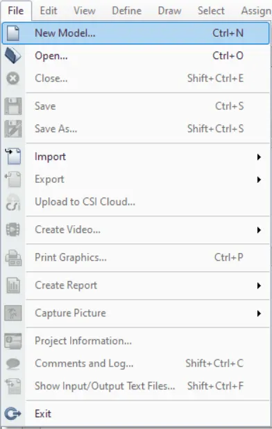
- After selecting the new model the new tab opens, in that tab we have to select 'Use Built-in Settings with' option.
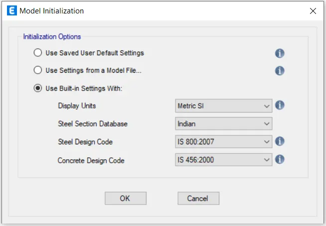
- After setting the model Initialization the templates tab will opens and, select the Grid only and press ok.
- Next we need to do the settings in Grid system data.
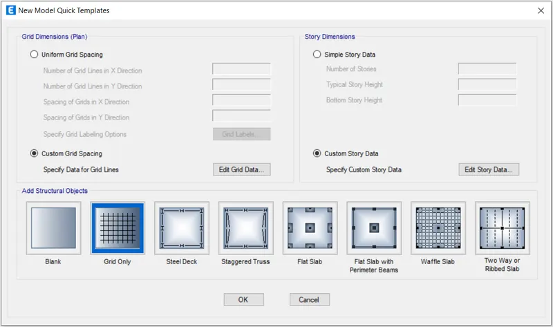
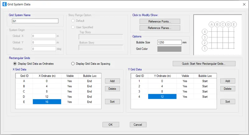
- Next we need to add the stories upto 25 story in the Story Data.
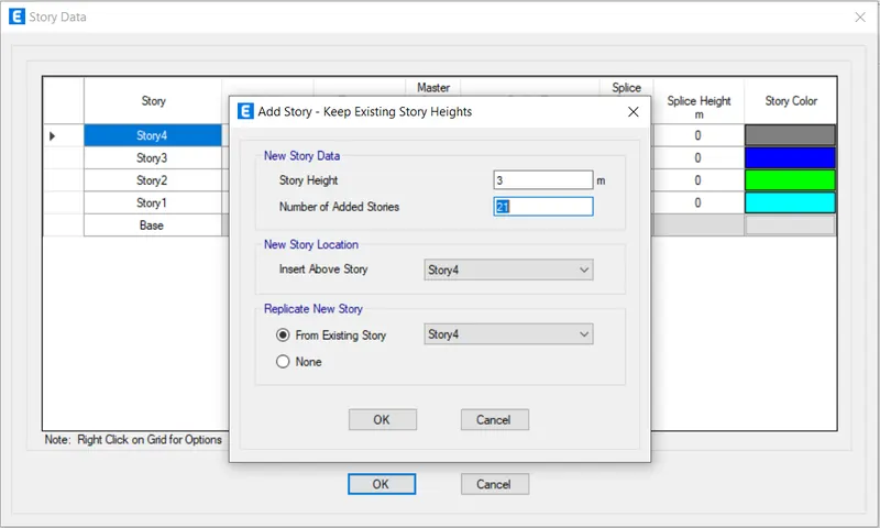
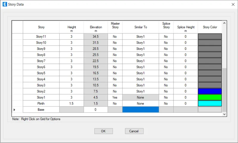
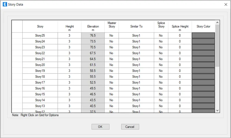
- The 25 stories are added in the Story Data.
Step:-2
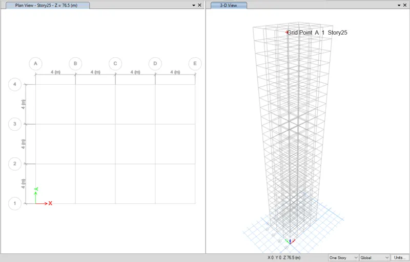
- Next the plan views are visible in the etabs screen.
- Next we need to open the 3d-view.
Step:-3
- Next we need to define option and select material properties.
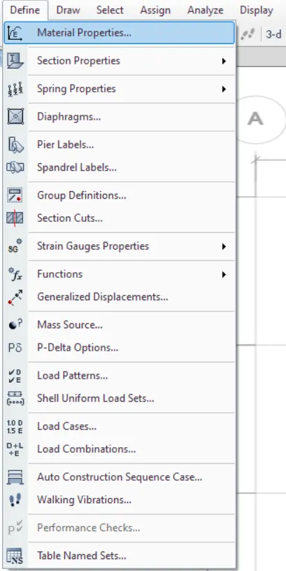
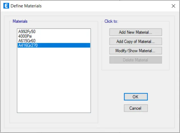
- After selecting the material properties the new tab appears, then we add new materials by selecting the Add new material option.
Step:-4
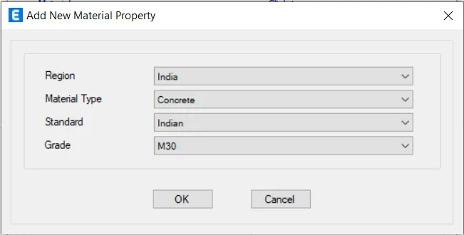
- Now we need to add material type as concrete and grade as M30.
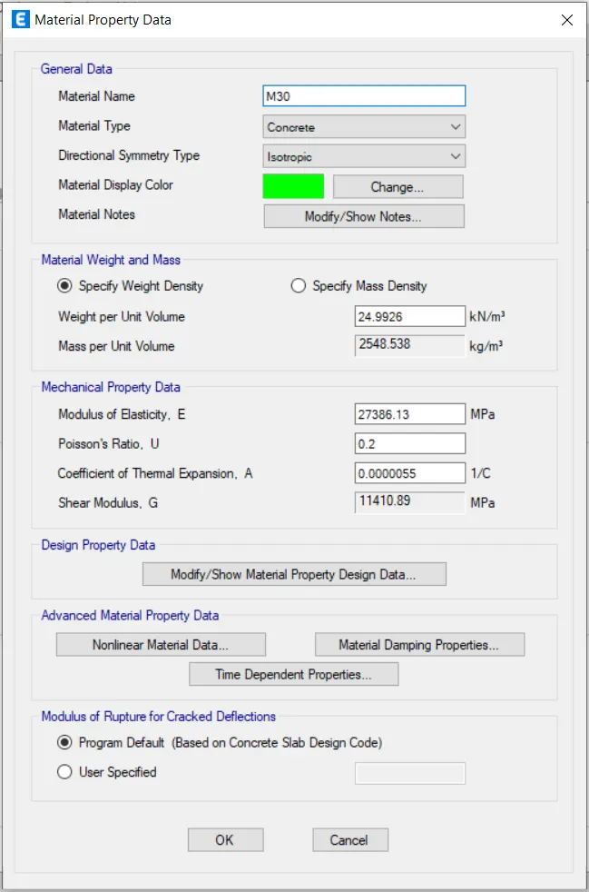
- Next we need to check the material property data, as shown below.
Step:-5
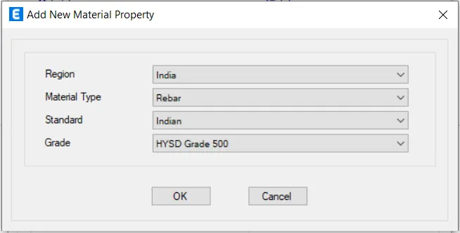
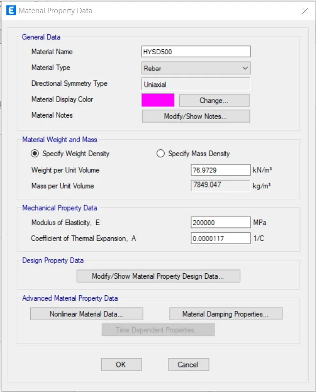
- Now we need to add material type as rebar and grade as HYSD Grade 500.
- Next we need to check the material property data.
Step:-6
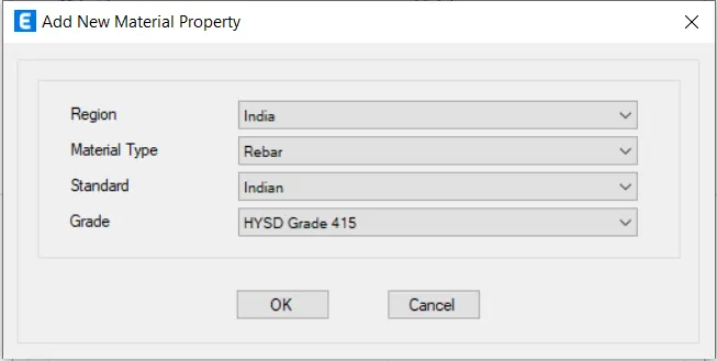
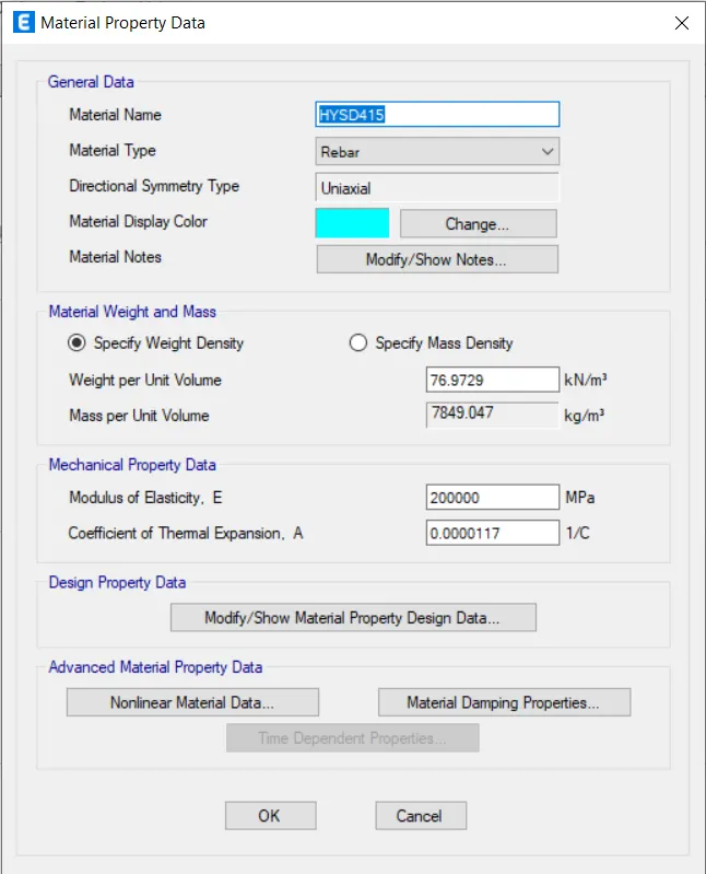
- Now we need to add material type as rebar and grade as HYSD Grade 415.
- Next we need to check the material property data.
Step:-7
- Now we need to select the section properties and click on the frame sections.
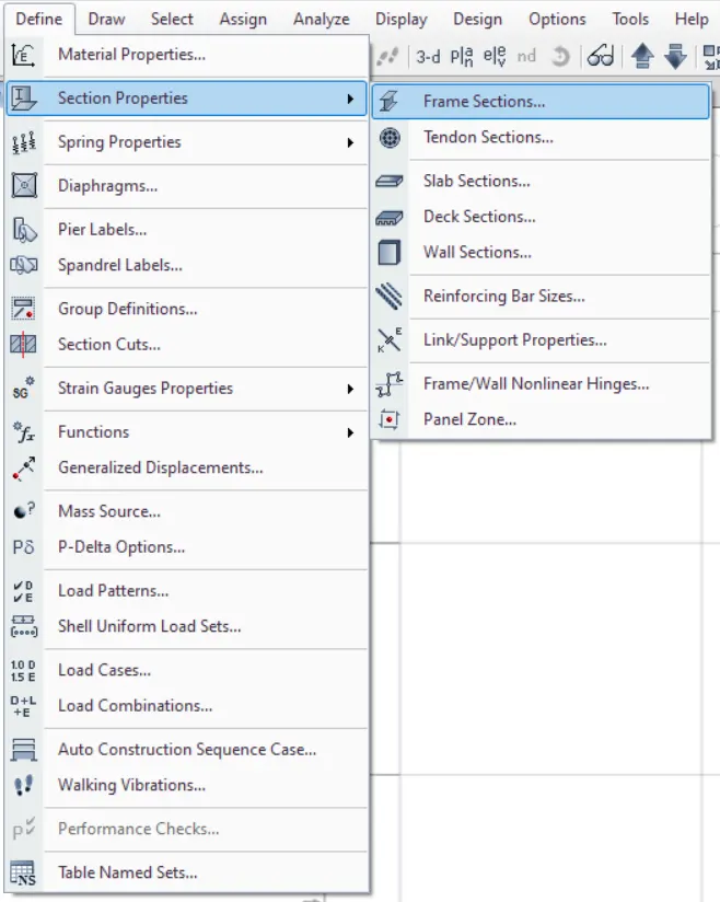
Step:-8
- After selecting the frame sections the new tab will be visible, in that we need to select the Add New Property.
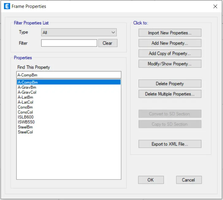
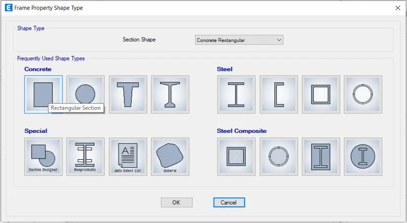
- After selecting the Add New Property, the new tab appears.
- In that new tab we select the Rectangular shape type in concrete.
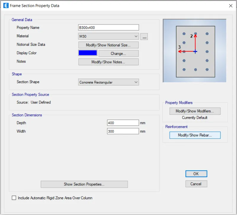
- Next the frame section property data will be visible, In that we add beam size as B300x400.
- Next we need to select the Modify/Show Rebar option.
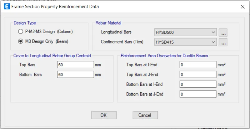
- After selecting the Modify/Show Rebar option the new tab appears, In that we select the design type as M3 Design only (Beam).
- Next we select longitudinal bars with the grade of HYSD500.
- Next we select Confinement bars with the grade of HYSD415.
- Again we have to select Rectangular shape type in concrete.
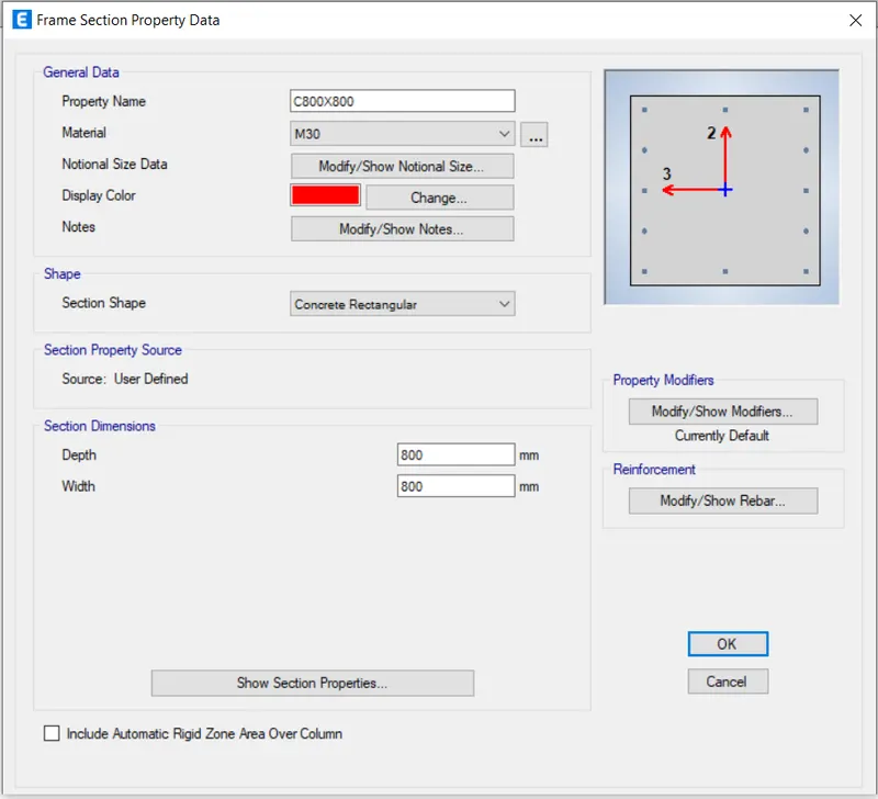
- Next the frame section property data will be visible, In that we add column size as C800x800.
- Next we need to select the Modify/Show Rebar option.
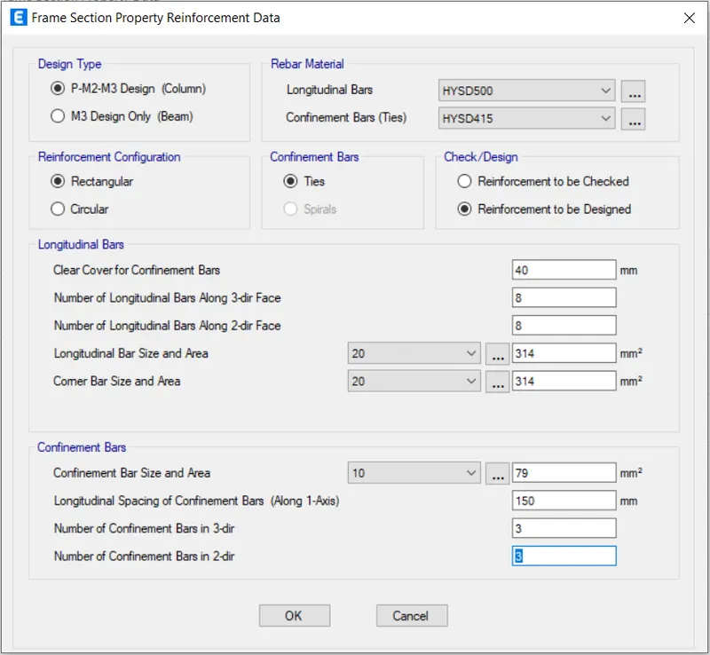
- After selecting the Modify/Show Rebar option the new tab appears, In that we select the design type as P-M2-M3 Design (Column).
- Next we select longitudinal bars with the grade of HYSD500.
- Next we select Confinement bars with the grade of HYSD415.
Step:-9
- Next we select the slab section option from the section properties.
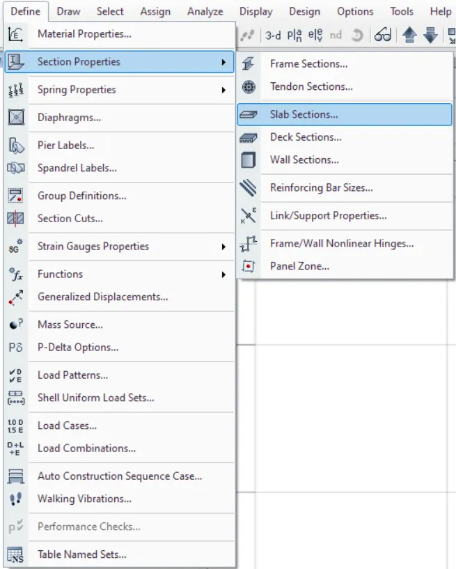
- Next the slab properties tab will be vissible, In that we select the Modify/Show Property option.
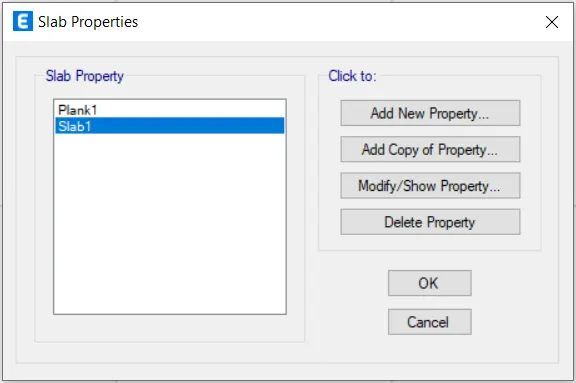
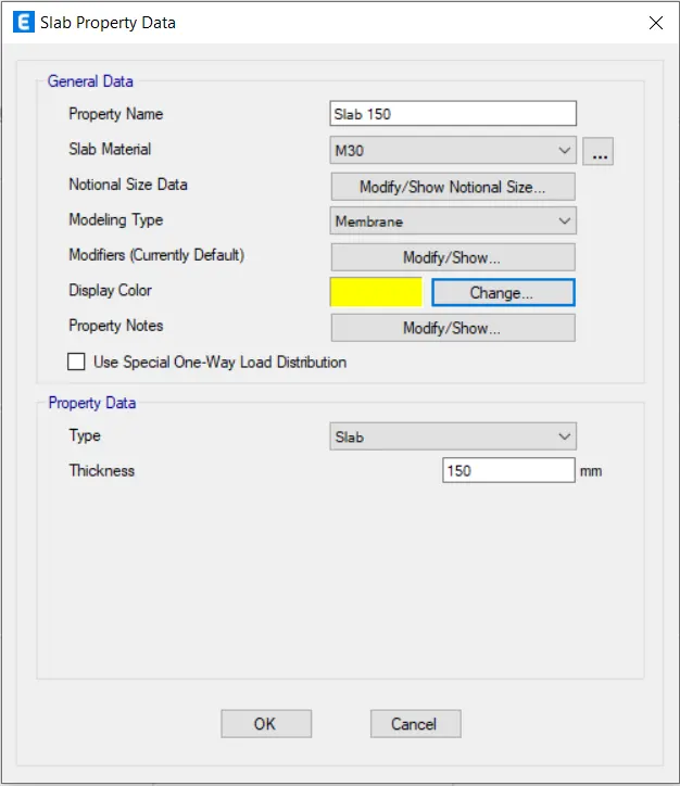
- After selecting the Modify/Show Property option, the new tab appears.
- In that we need to put the slab name as Slab 150, it means slab with the thickness of 150mm.
- And we take the concrete grade as M30.
- Next we have to click the ok option.
Step:-10
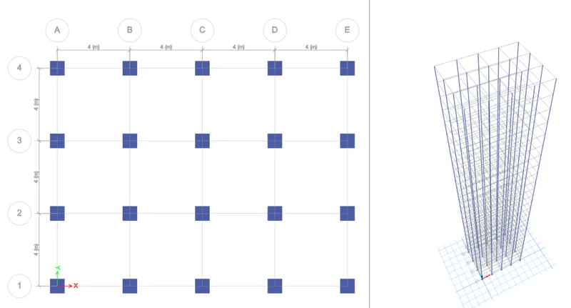
- Next we need to add the columns using the Quick draw columns option.
Step:-11
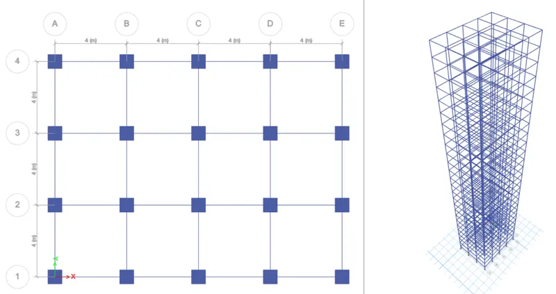
- Next we need to add the beams using the Quick draw beams option.
Step:-12
- Next we need to add the slabs using the Quick draw floor/wall option.
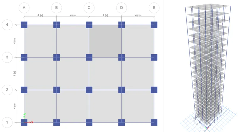
Step:-13
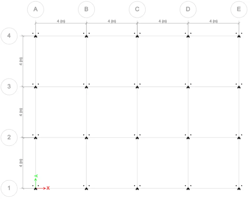
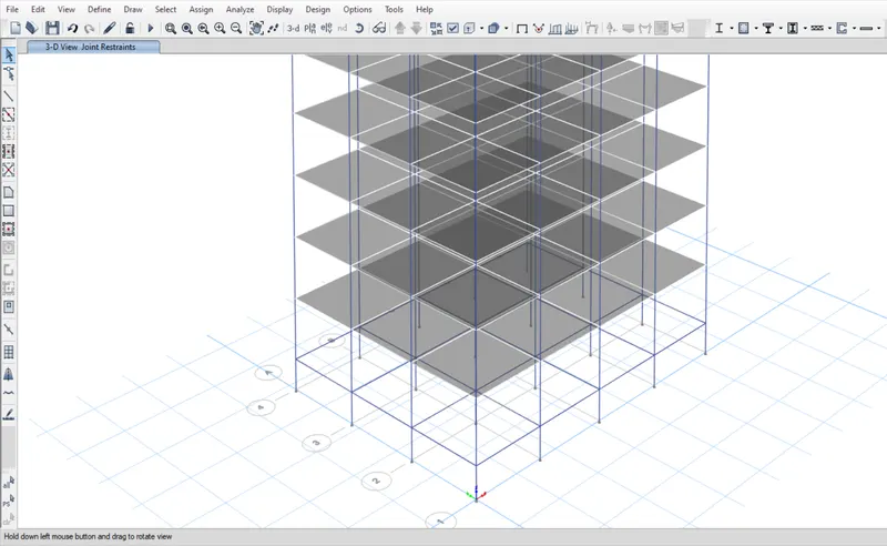
- Next we go to the base plan and select all base joints.
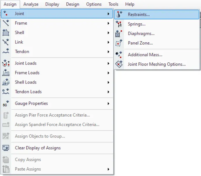
- Next we select the Restraints from joint option.
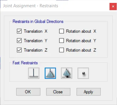
- Now we need to select the pin joint and click on apply and then click on close button.
- Thus, the pin-joints are added to the base of the structure.
Step:-14
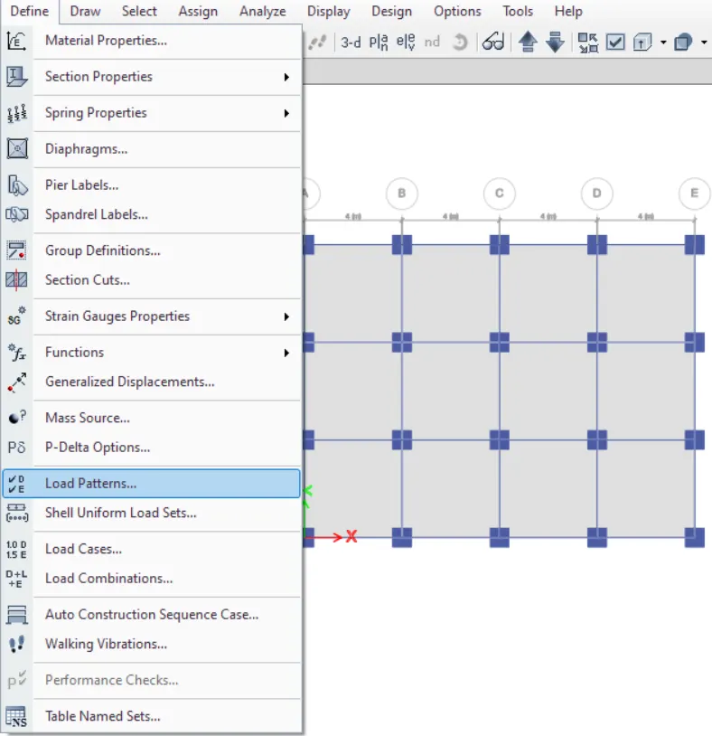
- Next we need to select the load patterns from the define option.
- Now we add Dead load, live load, Brickwall load, and earthquake load.
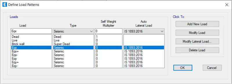
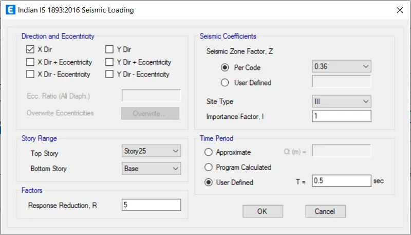
- Next we need to select eqx and click on the Modify Lateral Load, then the new tab appears.
- In this tab select X Dir and take seismic zone factor as per code is 0.36.
- And we need to select site type as lll.
- Next click on the ok button.
- Similarly, do this for all the seismic loads such as eqx+, eqx-, eqy, eqy+, eqy-
Step:-15
- Next we have to click on the assign option and then select shell loads, from the shell loads we select the Uniform option.
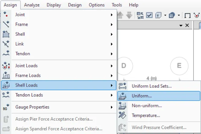
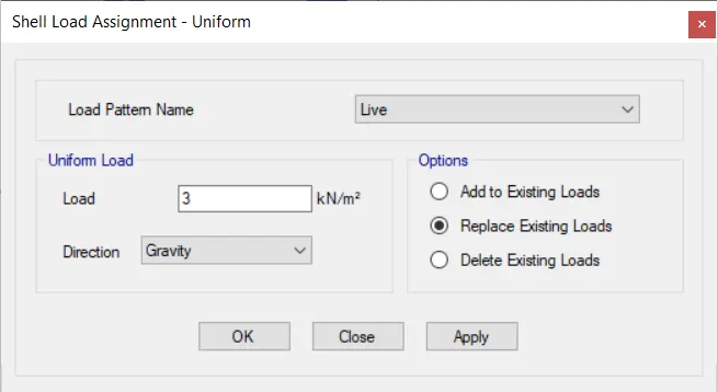
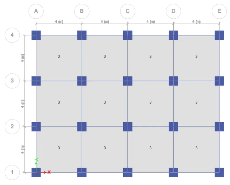
- Here we need to consider the live load upto the 24th floor with 3kN/m^2.
Step:-16
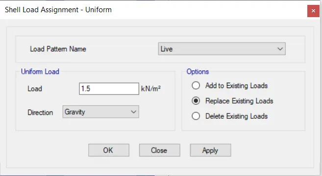
- Next we have to click on the assign option and then select shell loads, from the shell loads we select the Uniform option.
- Here we need to consider the live load for the 25th floor with 1.5kN/m^2.
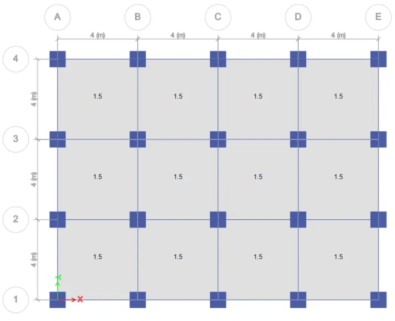
Step:-17
- Now we select the object type option.
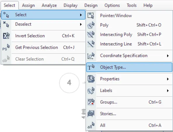
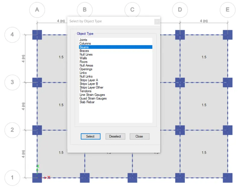
- After selecting the object type option, the new tab will be visible, In that select the beams and click on the select button and close.
- Next we select the distributed load from the frame loads.
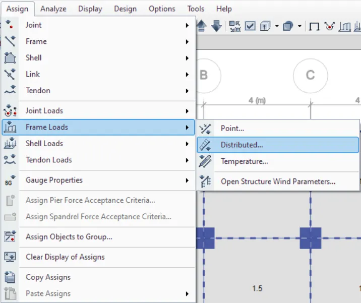
- Then after the new tab will appear, In that we select load pattern as Brickwall, and then click on the apply button and close.
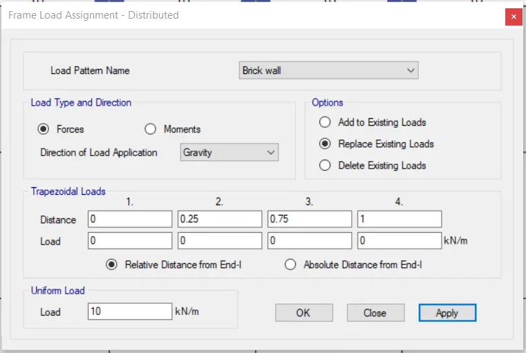
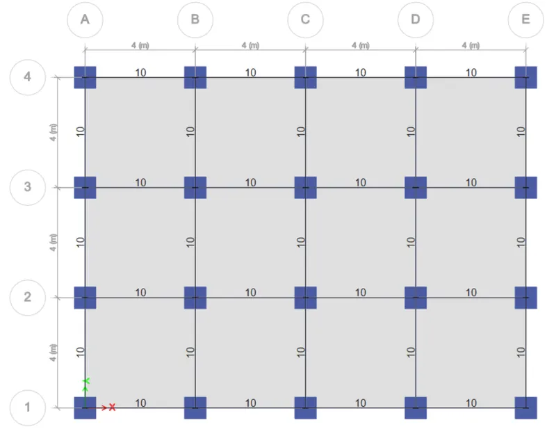
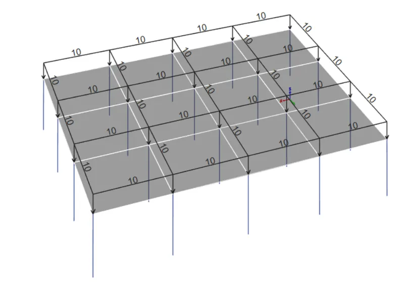
- Now we click on the toogle option to view the loads acting on the story.
Step:-18
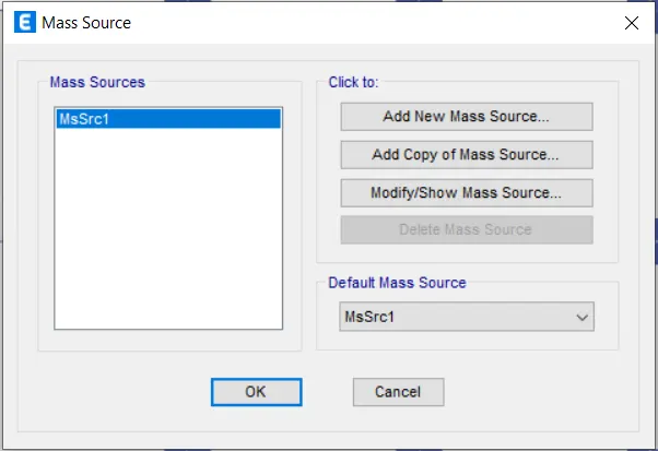
- Next, from the define option we select the mass source.
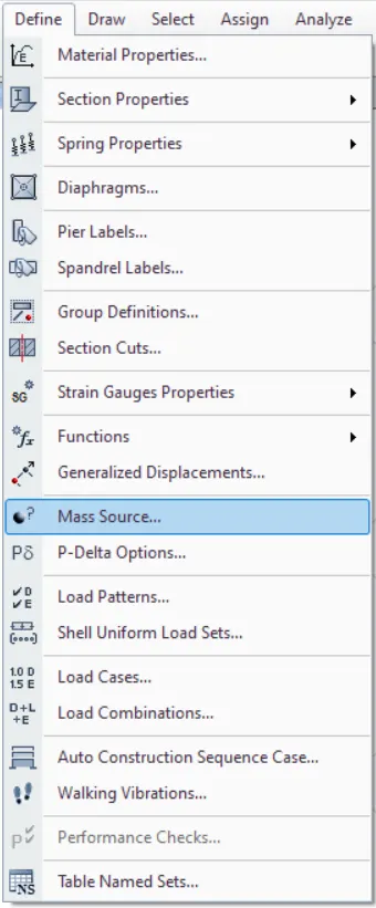
- In the mass source tab, we select Modify/Show Mass Source option.
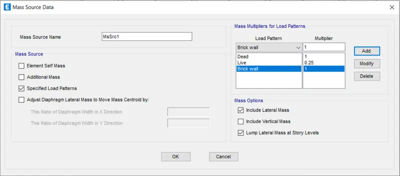
- Next we add the load patterns in the Mass Source Data.
Step:-19
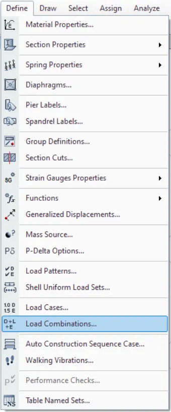
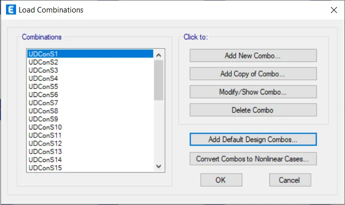
- Next, from the define option we select the load combinations.
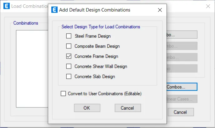
- After selecting the load combinations the new tab is visible, In that we select 'Add Default Design Combos' option.
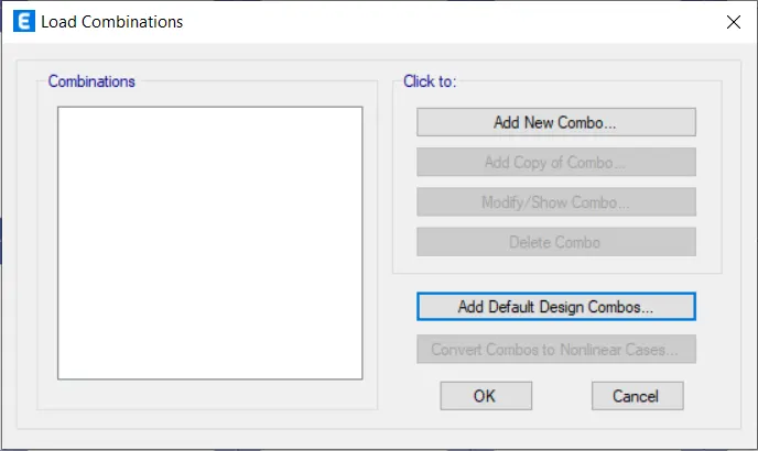
- Next we select concrete frame design in the Add Default Design Combinations.
- Now we can see here that the load combinations are visible.
Step:-20
- In the select option we select object type option.
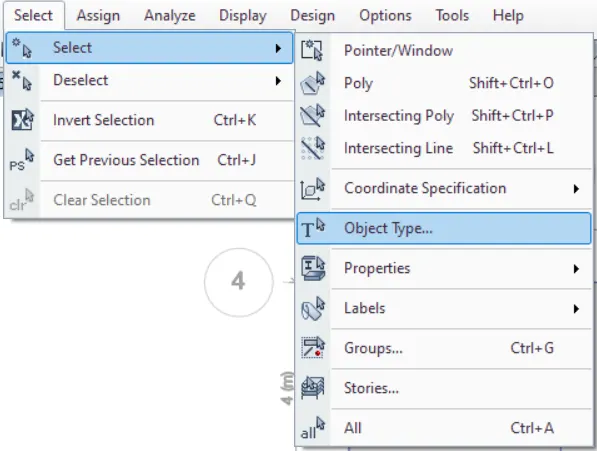
- After selecting the object type option, the new tab will be visible, In that select the floors and click on the select button and close.
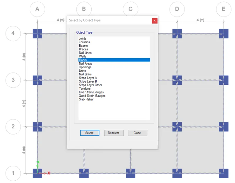
- Next we have to select the Diaphragms from the shell option.
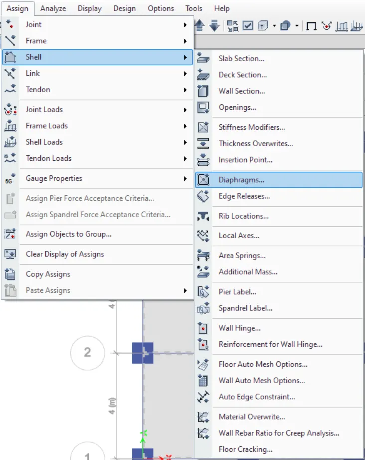
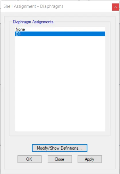
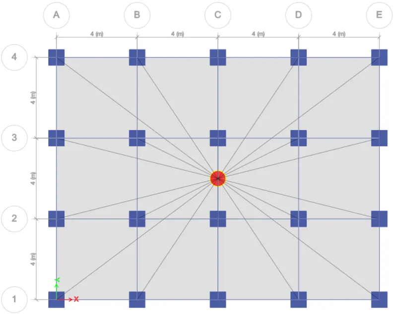
- After selecting the diaphragms the new tab will appear, in that select D1 and click on the apply button and close.
Step:-21
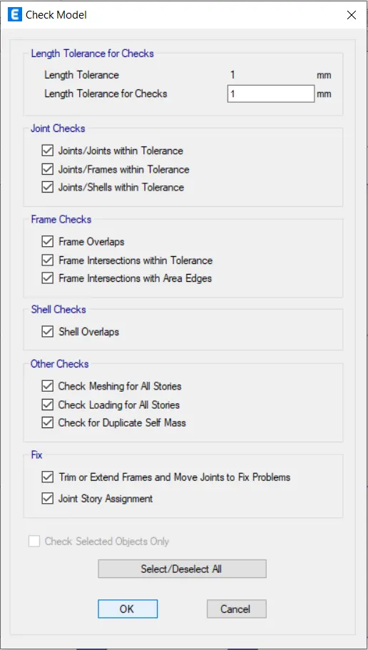
- Next we have to check the model by clicking the check model option.
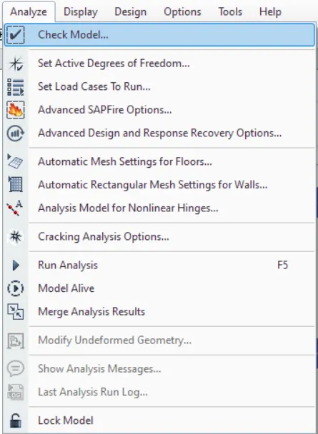
- Next the check model tab will appears, in that we select the all options and click on the ok button.
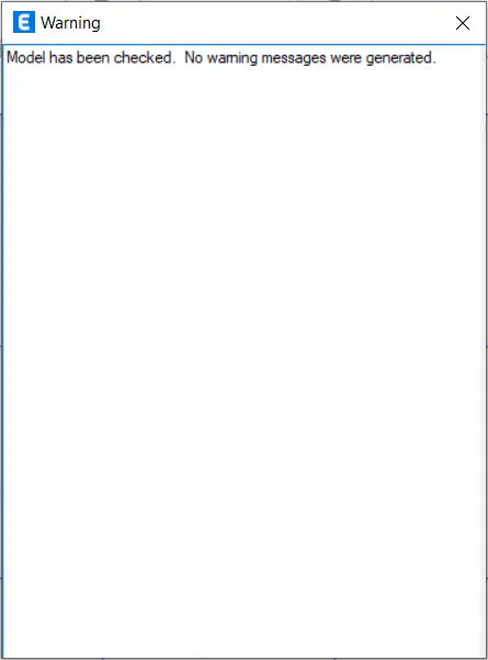
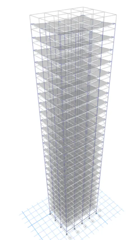
- After the model is checked, then the warning tab will be visible and it tells that there is no warning messages.
Step:-22
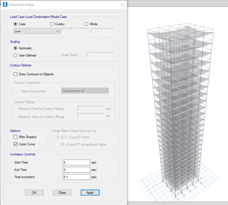
- Next we select the 'show deformed shape' option, then the new tab appears.
- In the deformed shape tab, we select live load in the load case
- Next we see the deformed shape of the structure with the live loads.
- Next we see the deformed shape of the structure with the Dead loads.
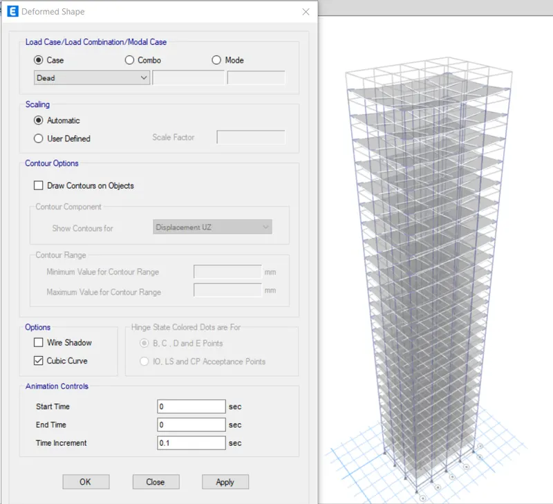
- Next we see the deformed shape of the structure with the Brickwall loads.
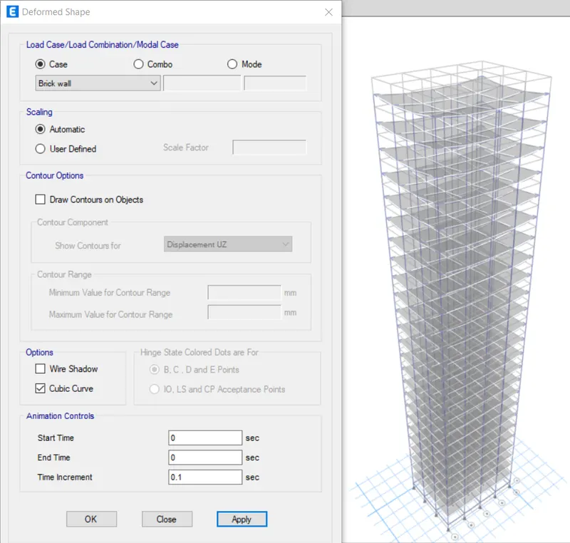
- Next we see the deformed shape of the structure with the earthquake loads.
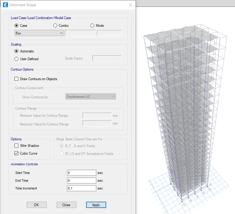
Step:-23
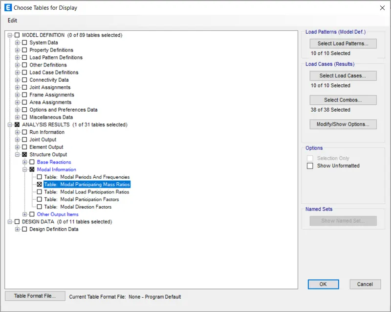
- Next, from the display option we select the show tables option.
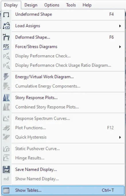
- After selecting the show tables option the new tab will be visible.
- Now we select the Modal Participating Mass Ratios and click on the ok button.
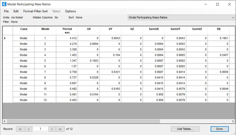
- Next the Modal Participating Mass Ratios table will be visible.
RESULT:-
- The 25 storey building has been modelled successfully in the ETABS 2018.