Modelling of 25 storey building with the specified properties using ETABS
Ans1. Aim- Model a 25 storey building on ETABS with structural properties as specified below. Ground floor or plinth floor level can be taken at a height of 1.5 metres from the base. Each of the successive 25 storeys has a storey height of 3 metres.
1. Frist open your ETABS software and open new file 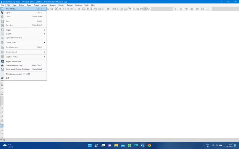
2. Then you have a option called model initialization and select use Built - in setting with:
metric SI, india, Indian and IS 800:2007, IS 456:2000 then click ok 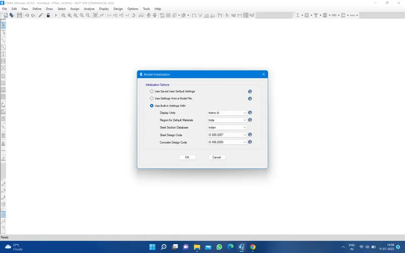
3. Then click on custom Grid spacing and custom story Data 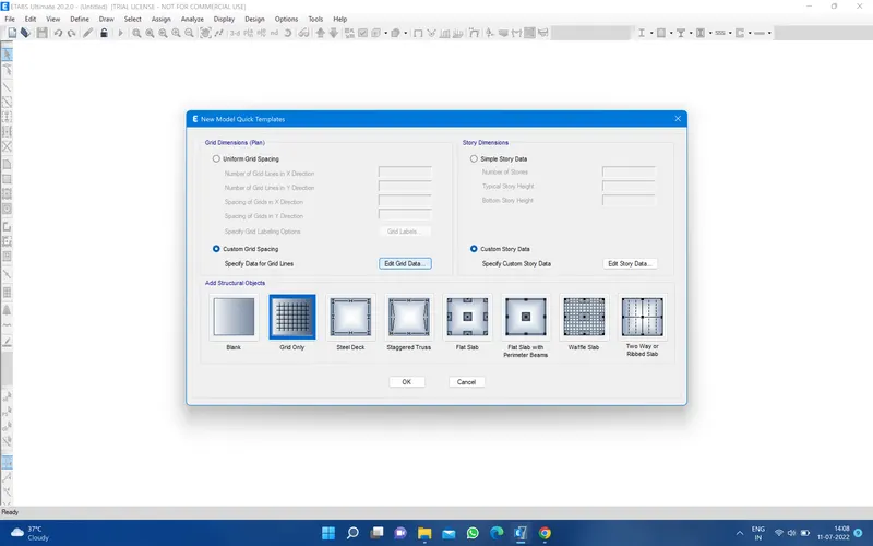
4.Then click edit grid data then edit the grid data duration 4m X grid data and Y grid Data then click on ok 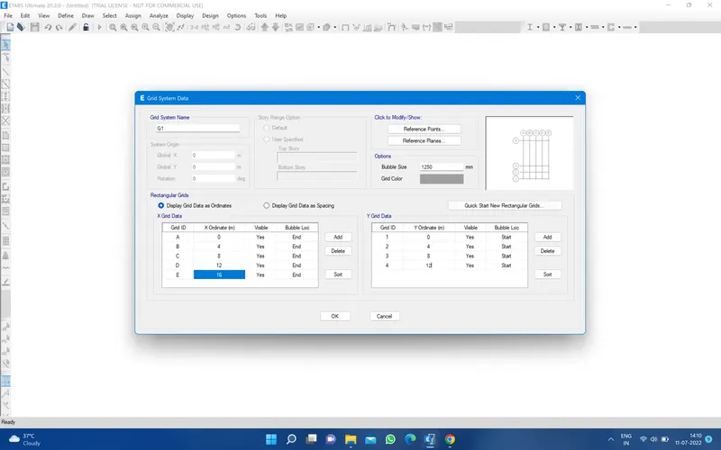
5. Then click on the edit story and add more 22 story for that left click in right arrow and drop down add story and lick on keep Existing story heights and number of add story 22 and click ok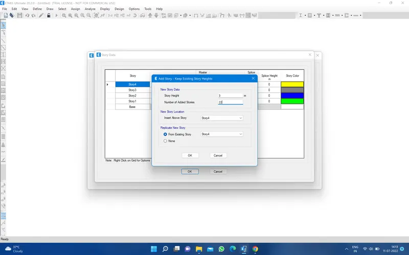
6. Then edit the all story as plinth 1st story and 2nd story ________and n story and last one roof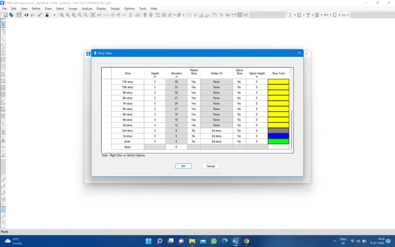
7. then edit the plinth height 1.5m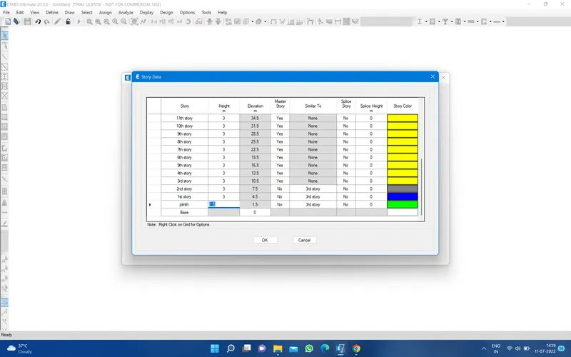
8. Then go to master story and select frist story yes and other one is NO
and go to similar to and select 2nd story to 23 th story select 1st story then click on ok and ok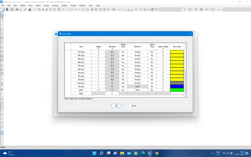
9. Go to Define and materials property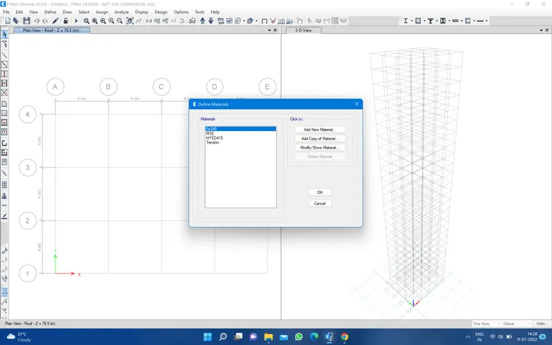
10. Then Go to add material and select the material and click ok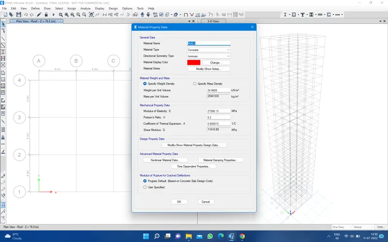
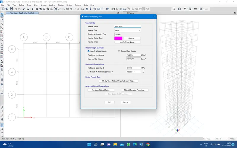
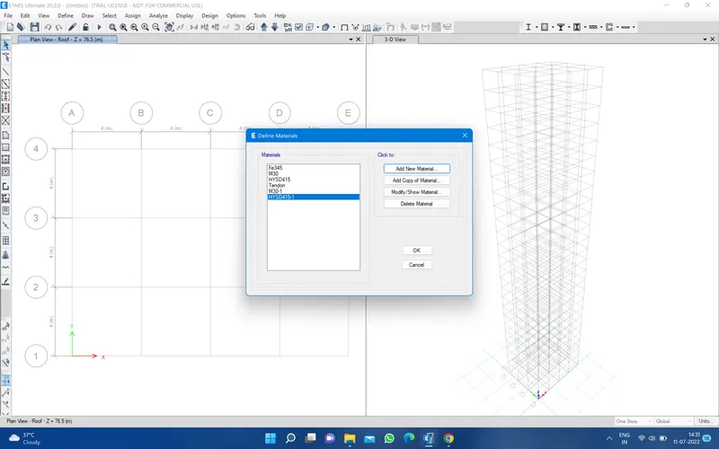
11. Again go define and select framsection 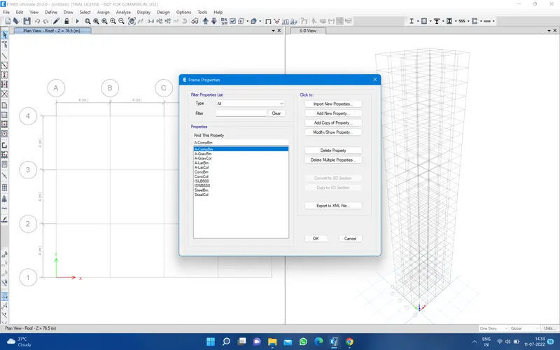
12. Then click on Add new property and select concrete and edit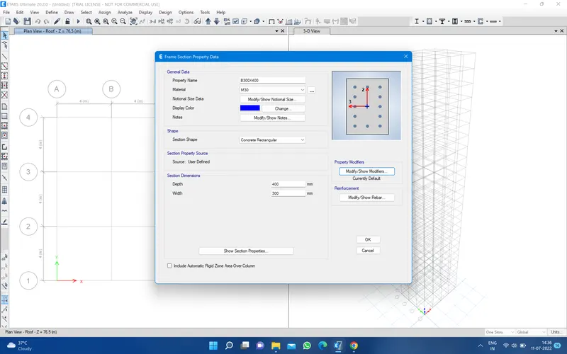
property modifiy no changes 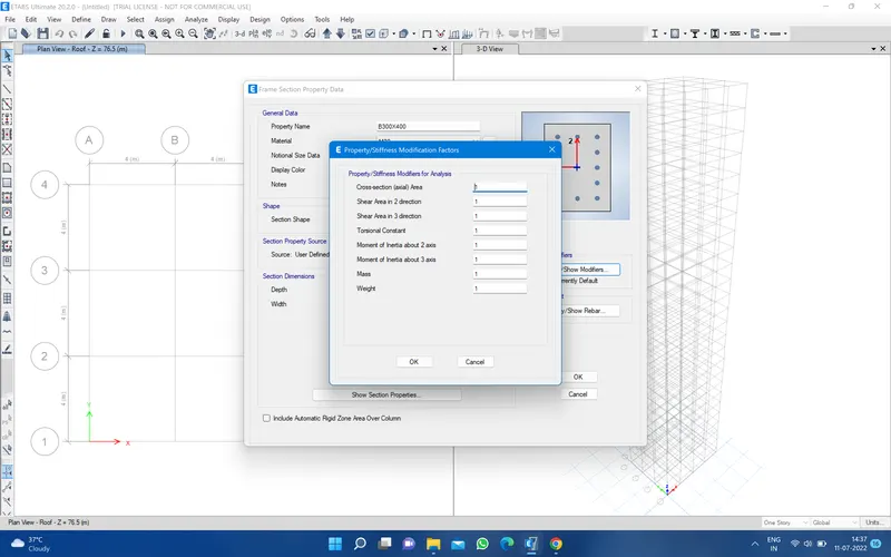
Then go to Reinforcement select Design Type M3 (beam) and Rebar material HYSD 415 and click OK 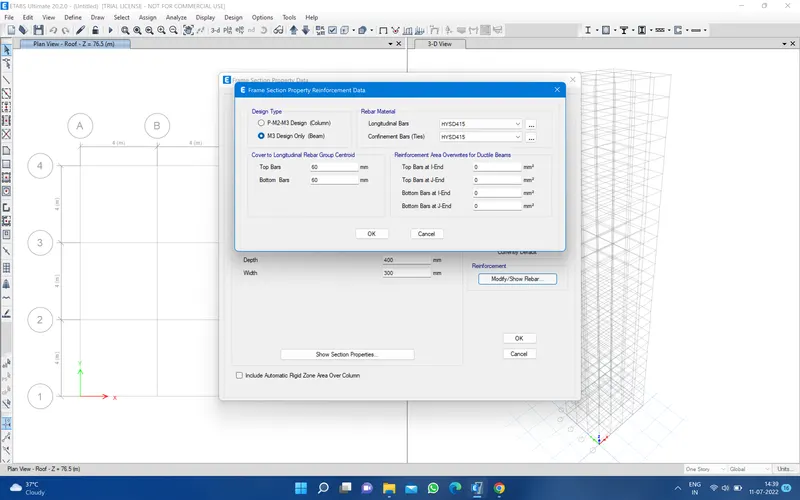
13. Now go for column and edit it 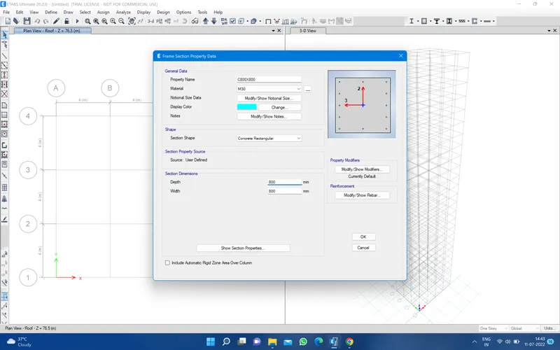
14 then property modifiers are not change 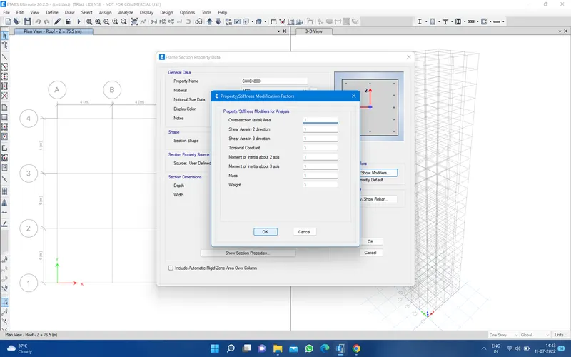
15 then go to Reinforcement select P-M2 (Column) and rebar material are also HYSD 415 and click ok, ok and ok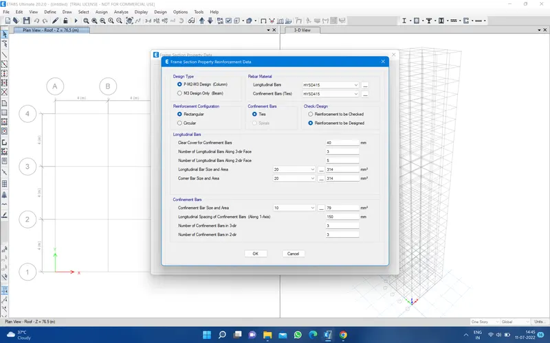
16. Go for define and section property and slab section 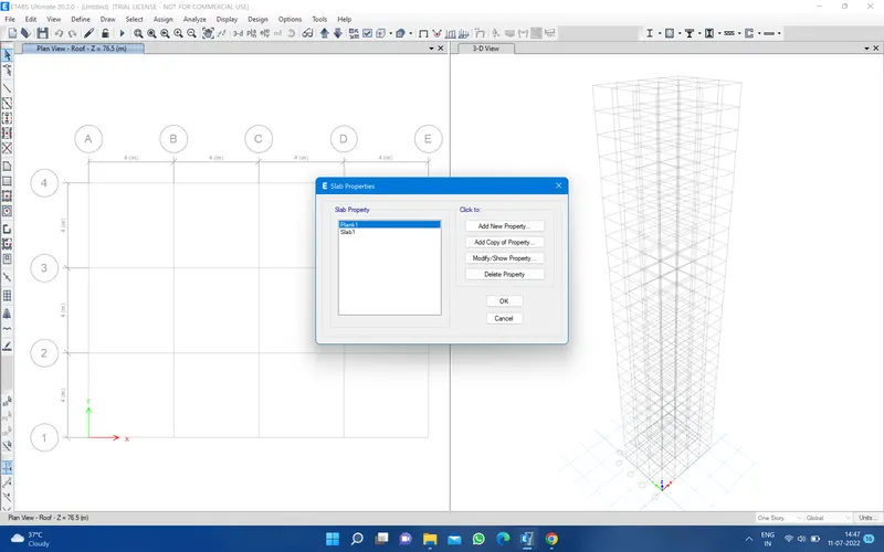
17. then go to add new property and edit the general data like S 150mm , M30, membrane and thikness 150mm and ok 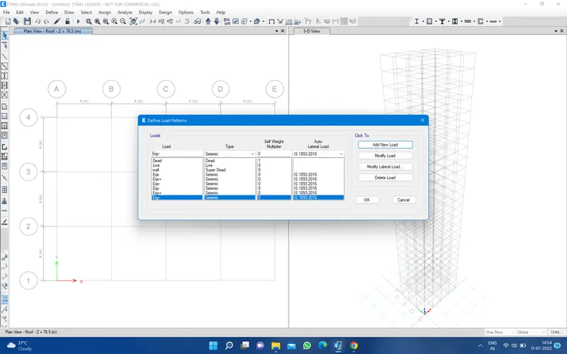
18. then go to definr and load pattern and add the new loads 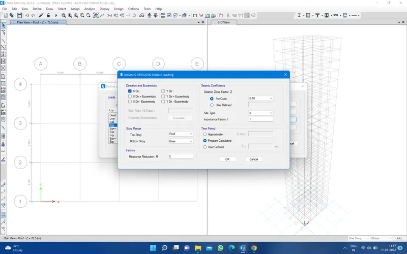
19. then go to modifiy lateral load and modifiying all the load 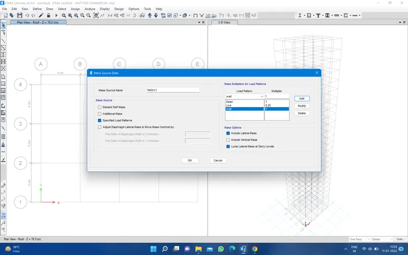
all modifying similar and click ok
20. then again go to definr and go to mass sourse and click on shown mass sourse and check on only specified load and click ok again on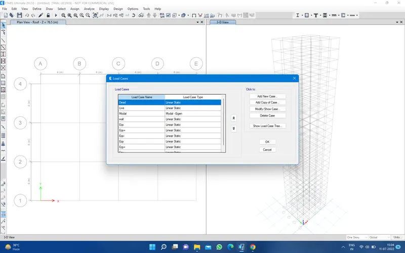
21. Again go to define and load case and click ok 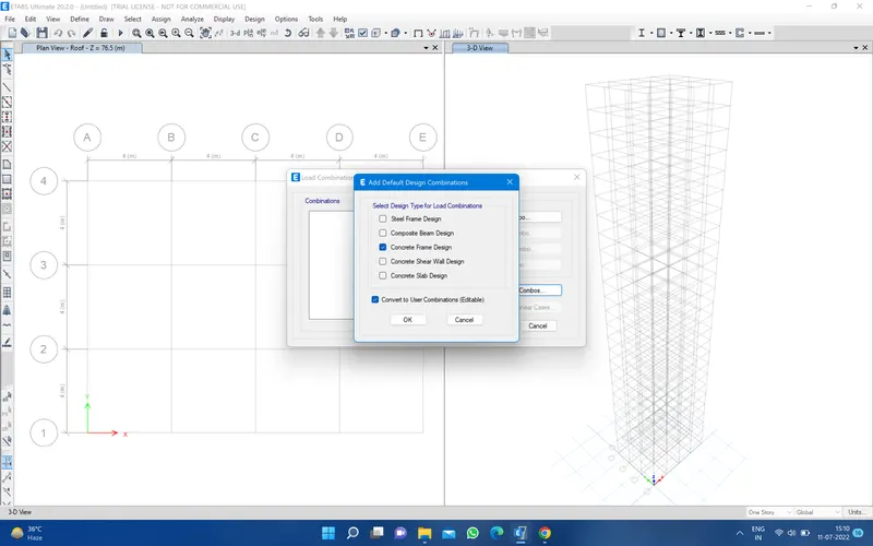
22. Now go to define and creat load combination and click on add define designe combos then check on concrete frame design check on concrete frame designe and convert to user and click ok 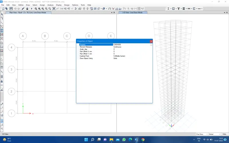
23. Go to right edge and click on quick draw column and select thr column size from the property 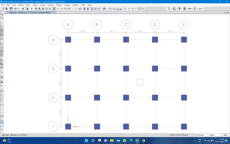
and select on the left lower corner 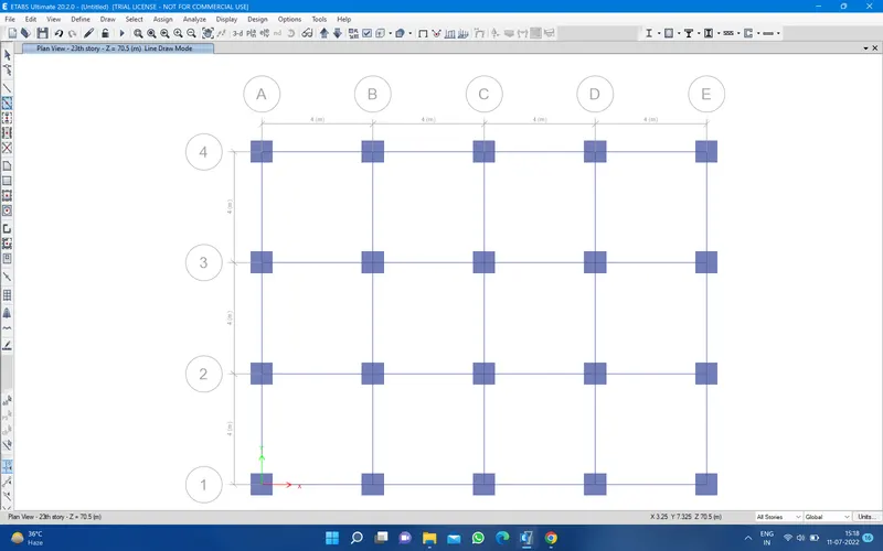
all the stories and assign the all column
24. Now go for quck draw beam and assign 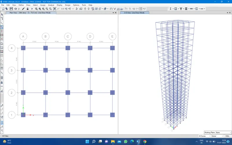
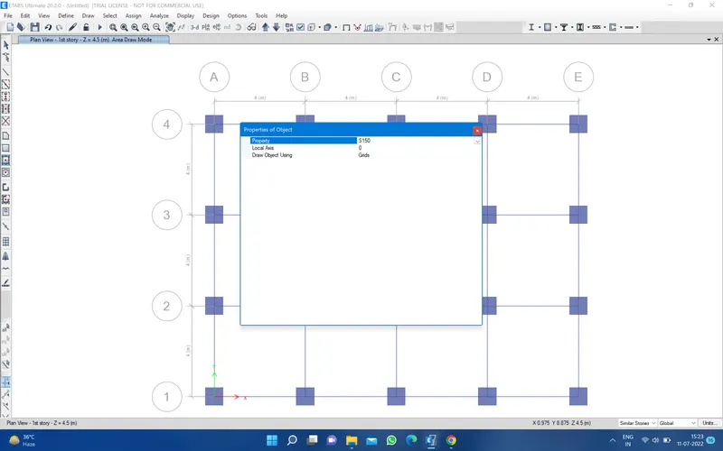
25. Now go to plan and select the level 1st story and change type to similar story
26. Then go to the slab then click on quck draw floor and select the property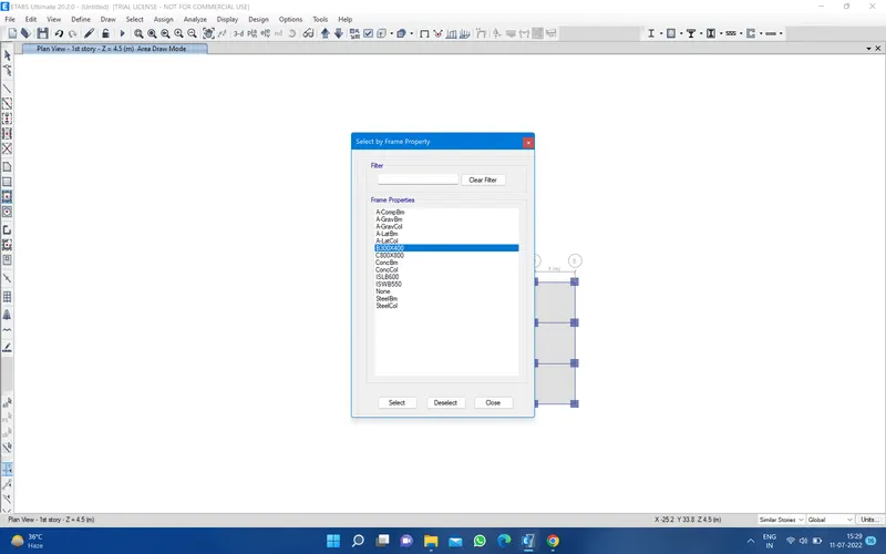
27.then assign the every floor 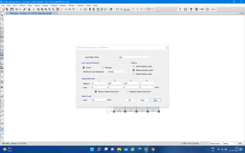
28. Then go to select and go to property and select all the beams and click on select 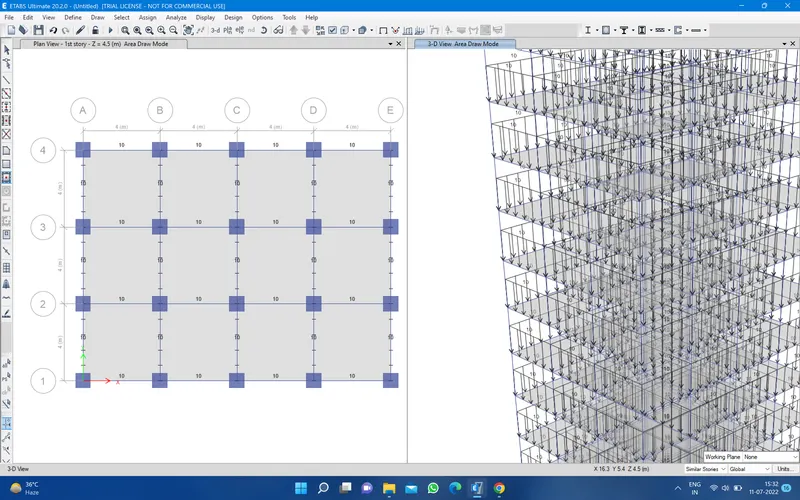
29. Then assign the load then go to from load and distrbution and select wall and load 10 kn/m then click apply ok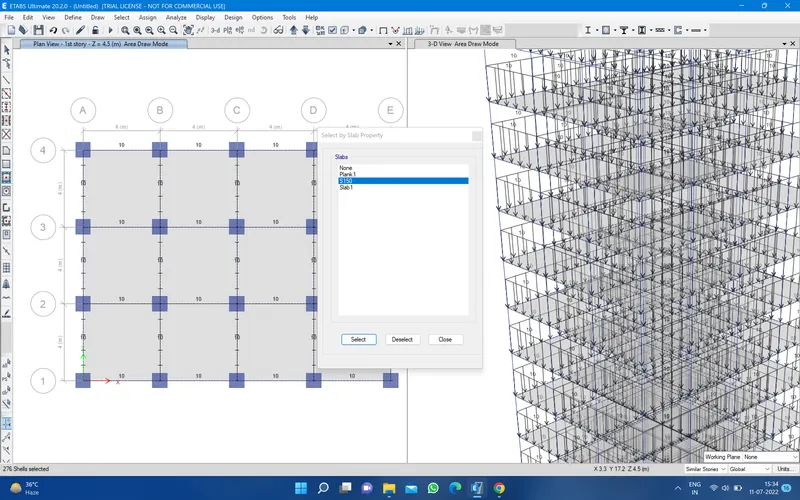
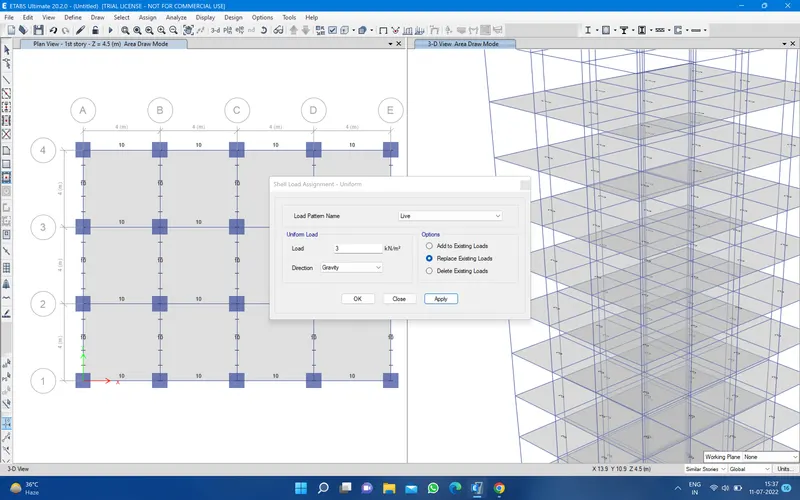
30. Go to select go to property and slab section and select slab S 150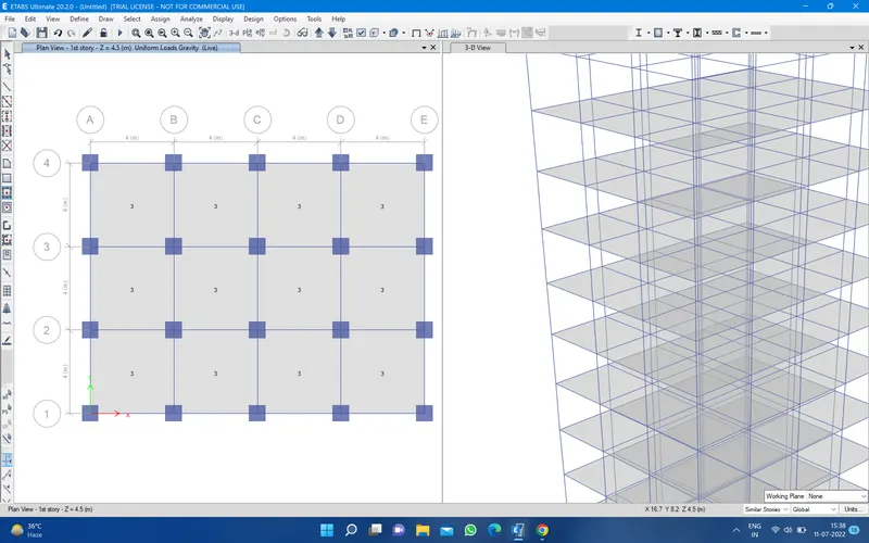
31. Go to assign and shell loads and uniform and select live and load 3 kn/m^2 apply and close 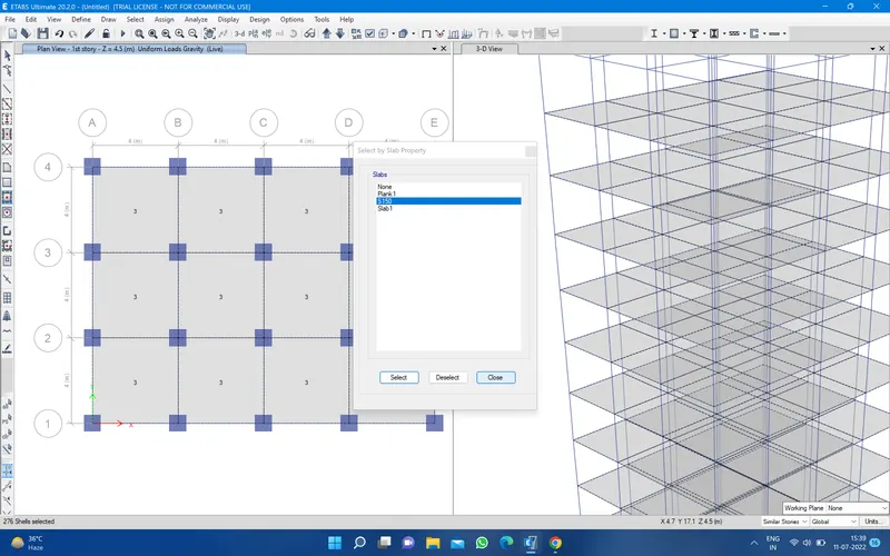
32. Go to select and property and slab section and select to S 150 select and closed 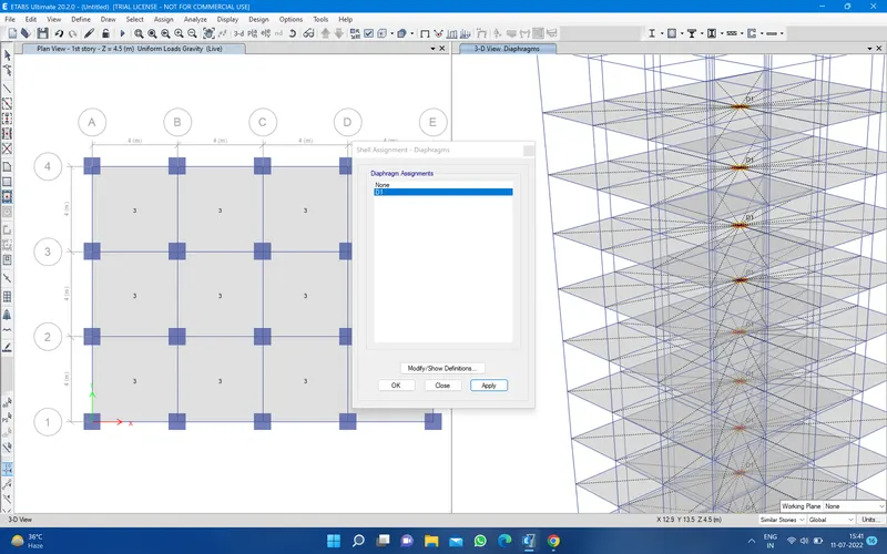
33. Go to assign go to shell and diaphragms and select D1 apply and ok 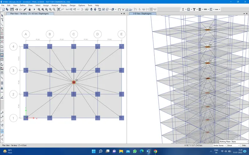
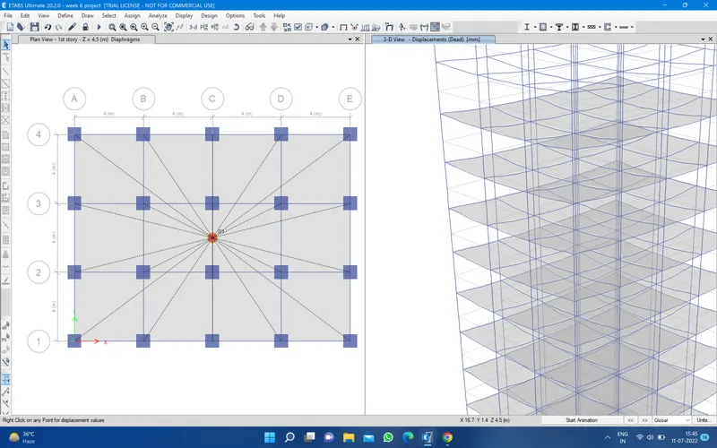
34. then go to analize and save the model in any floor anf naming it 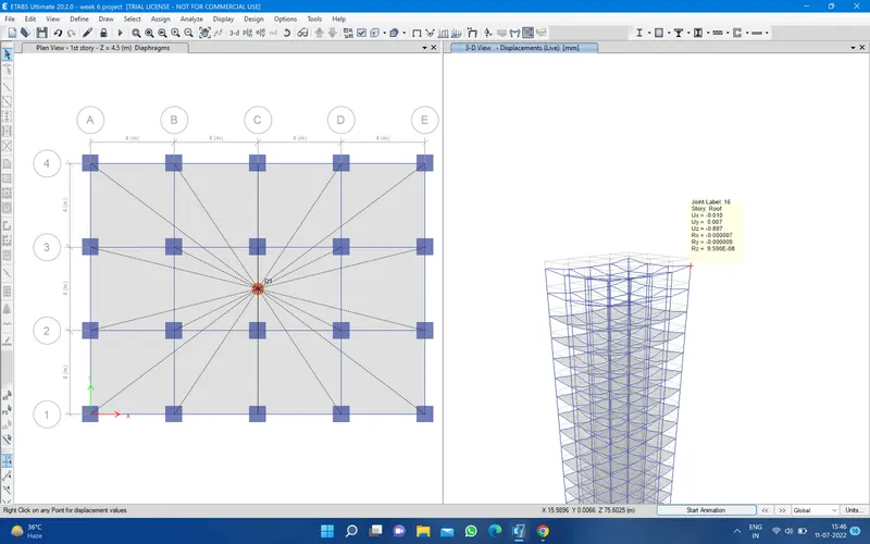
35. just go into table and go to analysis result and go to model intormation and model priods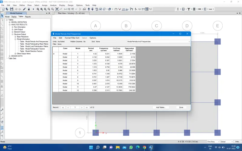
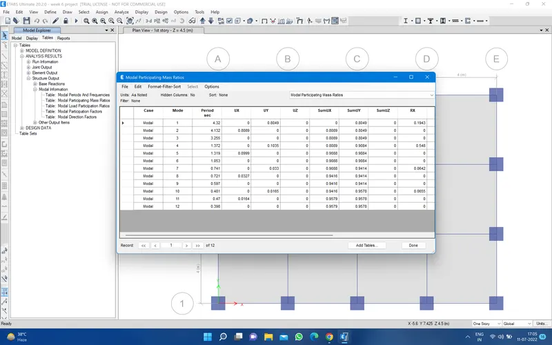
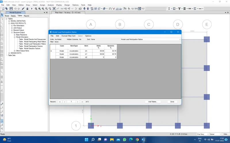
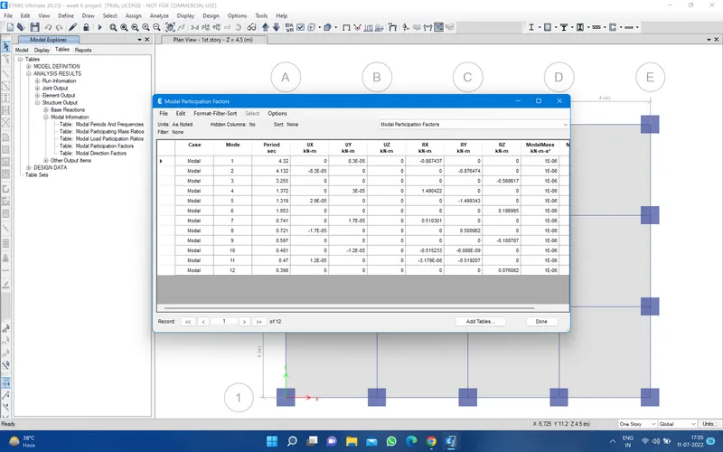
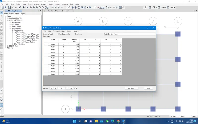
all the table show in the screen short