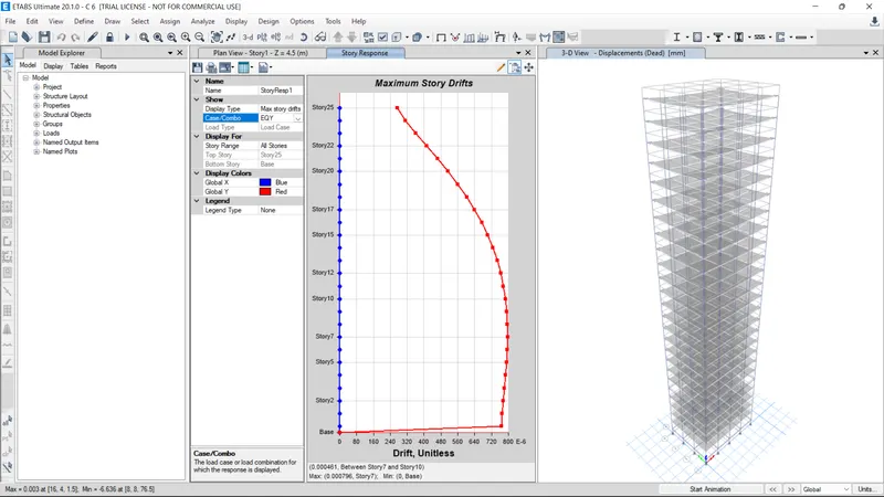
Modelling of 25 storey building with the specified properties using ETABS
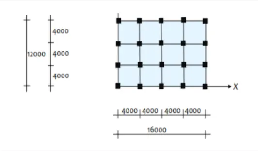
Structural Element Sizes
- Beams : 300 × 400 mm
- Columns : 800 × 800 mm
- Slab : 150 mm thick
Material Properties
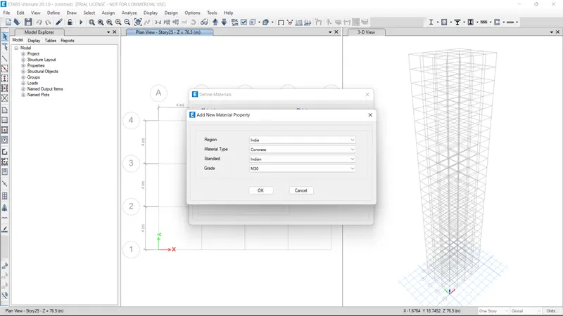
- Grade of Concrete : M30
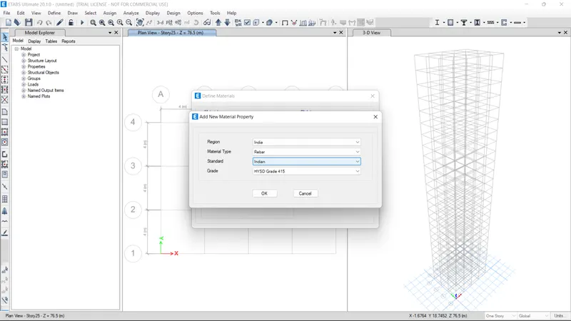
- Grade of Steel Reinforcement Bars : Fe 415
Loading
- Dead Load on beams from infill wall : 10 kN/m (Let us assume the same for roof floor in view of parapet)
- Live load on floor : 3 kN/m2 (Let us assume the same for roof floor)
a) Buildings are assumed to be pinned at the base
b) All columns in all storey are of the same size
c) All beams in all storeys are of the same size
d) Building is located on Soil type-II and in Zone-III.
Structural Analysis was done in ETABS 20
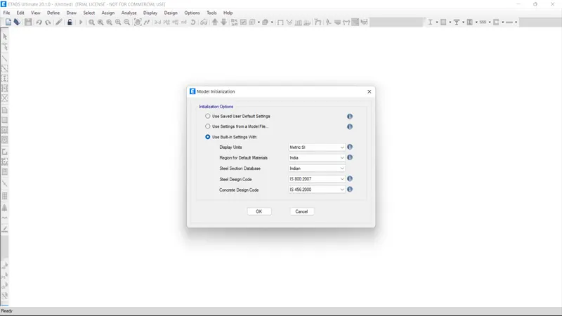
Open the software and input the model initiloisation data
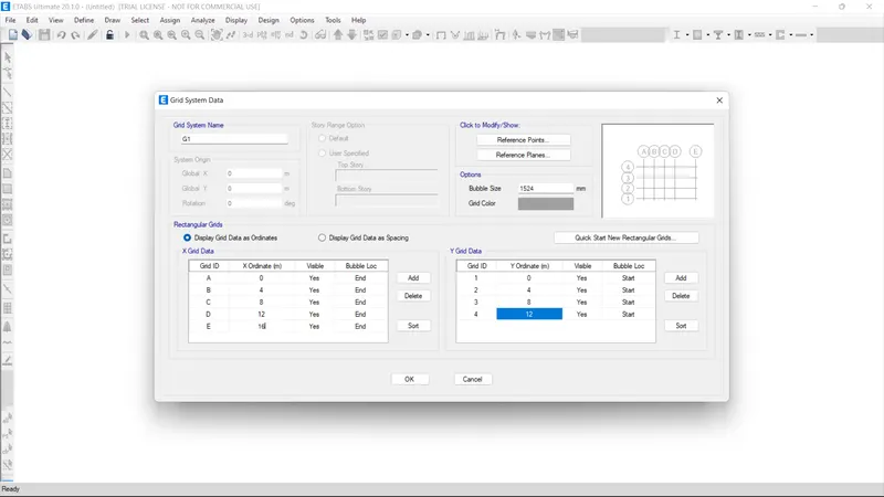
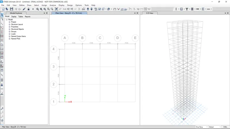
Set the grid system in Grid System data and input the grid as ordinate as provided in the floor plan of the building in X and Y direction
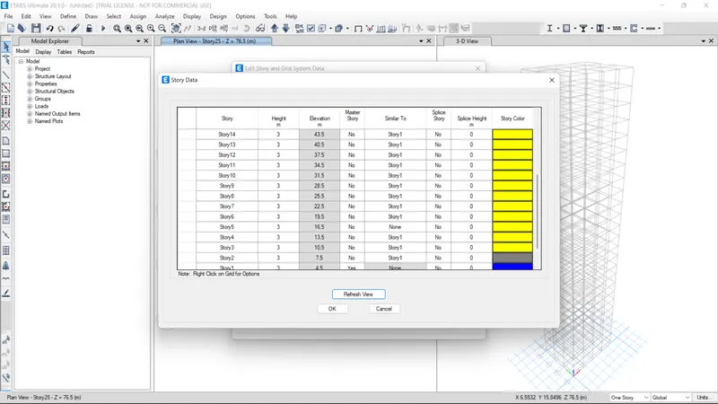
Set the story data by cosidering plinth beam level and all 25 floors in story data window. Height of each floor is 3m . Height of Plinth beam level is 1.5m above the foundation level.

Since the given plan is typical story data , consider the Storey1 as master storey and all other floor is similar to Storey1 all the way up to storey25
Now define the material data for the structure M30 grade concrete and Fe415 grade steel in define materials data
Now defining Frame sections for Columns Beams and Slab sections.
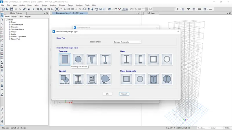
Column sections 800 x800 mm
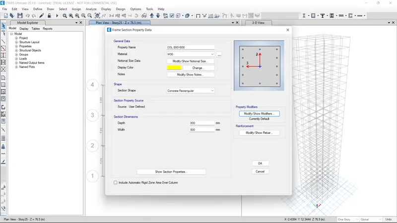
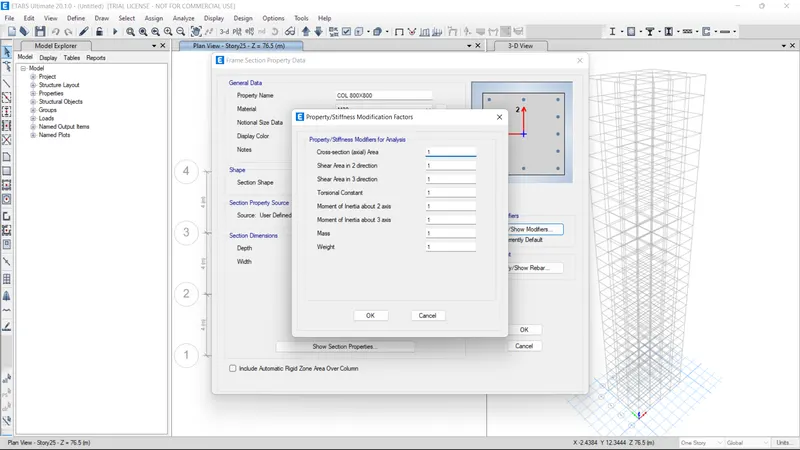
Since we are not designing the Frame section just provide the property modifiers as it is (1 for all). If we going for Frame design we have to provide Gross moment of inertia value for beams as 25% and for columns 70%.
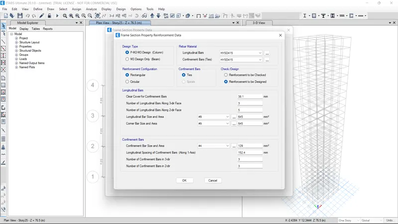
column longitudinal bar and lateral ties data
Beam sections 300x 400
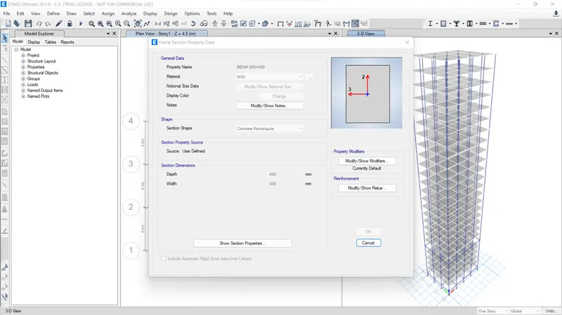
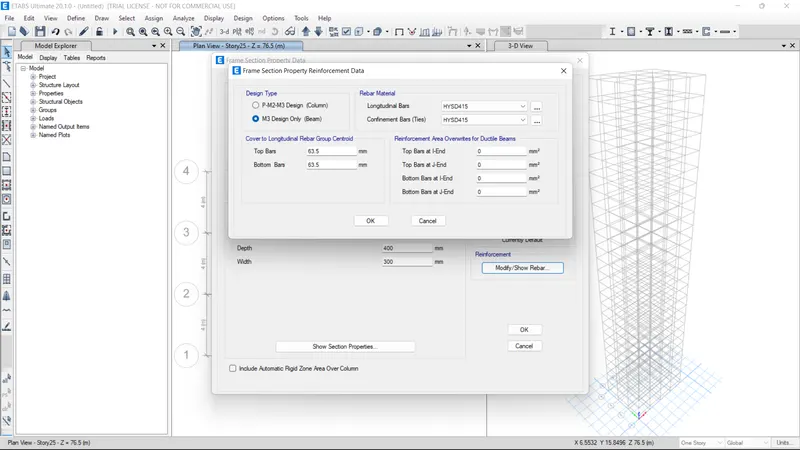
Main bar and Stirrups data
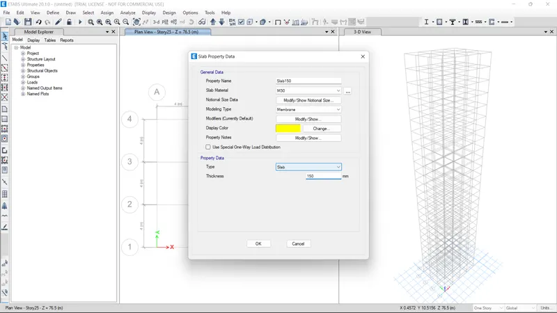
Slab sections t= 150 mm. since we are not considering the flange effects in analysis choose "membrane" as slab modelling type
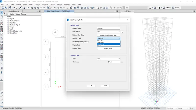
Geometric and material properties of RCC slab
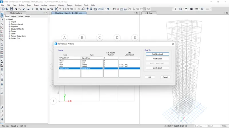
Now applying load patterns in analysis. Here we are considerin Selt weight ad dead load, Live loads, Wall loads as Super dead loads, Earthquake loads without eccentricity effects( for this analysis only) only EQX and EQY. Only self weight has the self weight multiplier 1 and others defined as 0. Earthquakre loads are defined as per is 1893:2002.
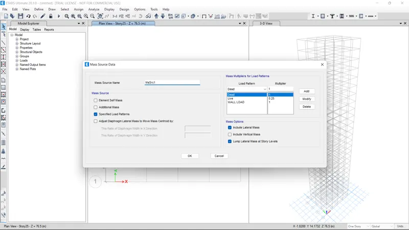
Now define the mass source (amount of mass of the structure contributing the lateral action of the building under seismic action). Full mass of dead load considered (Multiplier =1) . 25% of live load (Multiplier =0.25) and super dead load (Multiplier =1) applied.
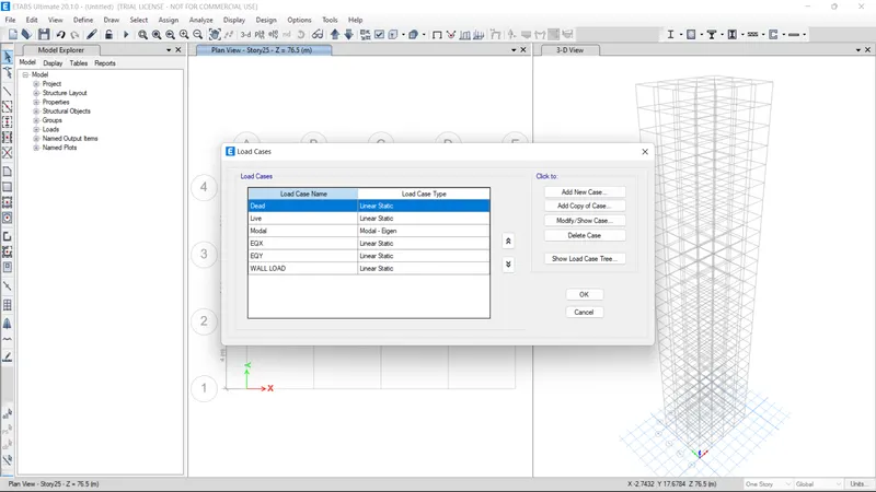
Load cases provided for the analysis are
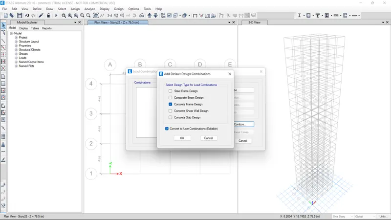
Load combinations provided for the analysis . Now we providing default combinations by the software as per is 1893
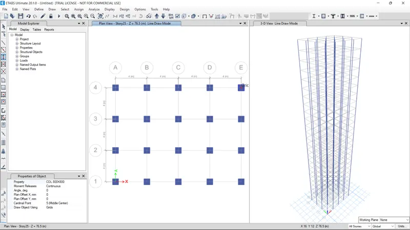
structural members are drawn on the grid system
Columns
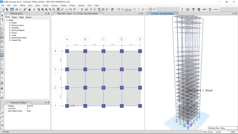
Beams and Slabs
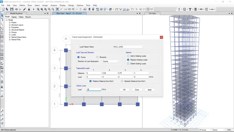
Applying loads on frame elements
On beams uniform load of 10kN/m as distributed super dead. select all beams and apply uniform load 10 kN/m
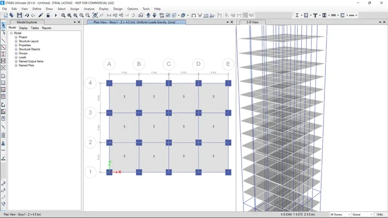
Apply slab loads as live load and apply the given quantity of 3kn/m2
Now define and assigh diaphrams to find out centre of rigidity and centre of mass distribution. since it is a regukar struture both may coincide.
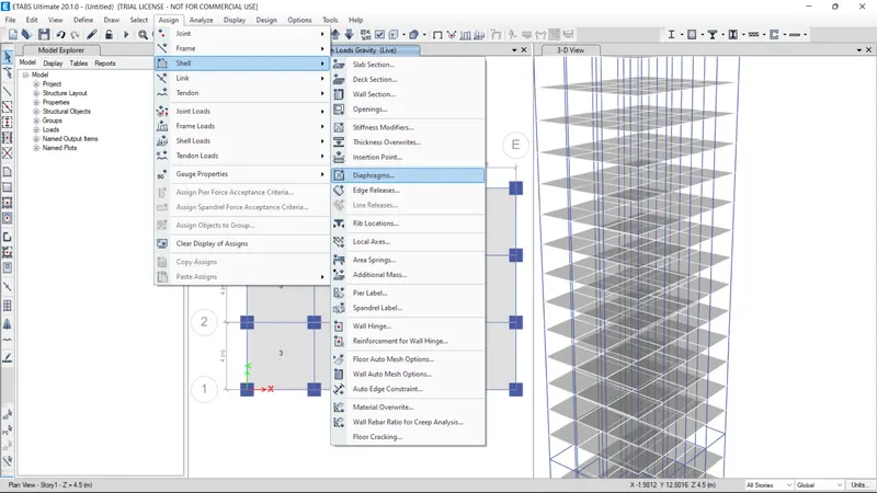
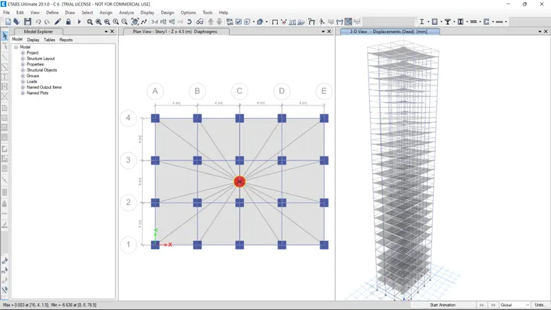
Ran the analysis and checking the result and comparing with is codal provisions.
a) Translational fundamental natural period of vibration in both the x and y direction is approximately Tx1= 4.4 second and Ty1= 4.2 second
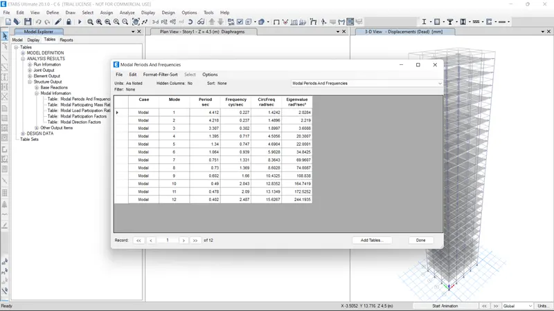
Result- period of vibration of mode 1 (fundamental mode in x direction)= 4.412 sec almost equal to 4.4 sec and mode 2 4.218 sec (fundamental mode in y direction) almost equal to 4.2 sec provided in problem. So results are matching.This check will help confirm if modelling is done correctly. Some deviations from the above values is possible (± 2%). But any major deviation will suggest an error in modelling.
b) Torsional irregularity check
The natural period corresponding to the torsional mode of oscillation must be less than the two fundamental translational modes of oscillation along each principal plan directions as per Table 6 is 1892:2016
Torsional mode (mode 3) , T= 3.307 which is less than 4.412sec (mode 1) and 4.218 (mode 2) [fundamental modes of vibration in pricipal plan directions]. Hence the results satisfied.
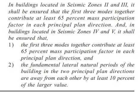
c) Case1 - Vertical irregularity check as per clause 7 in Table 6 (shown below) of IS 1893 (part 1)
Checking the data of modal mass participation ratio from ETABS.
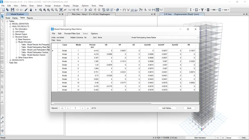
First three modes alone provide 65% of mass participation in each principal plan direction. Here mode 1 alone contributing more than 80% of mass participation. Hence satisfied the condition.
Case 2 -The fundamental natural period of the building in the two principal plan directions area away each other by 10% of the larger value.
T of mode 1 = 4.412 and of mode 2 is 4.216 . maximum allowable time period of mode 2 is 90% of mode 1 which is 3.97. Obtained is 4.216 which is higher . Hence the condition not satisfied.
d) inter-storey drift limitations in clause 7.11.1.1
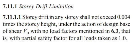
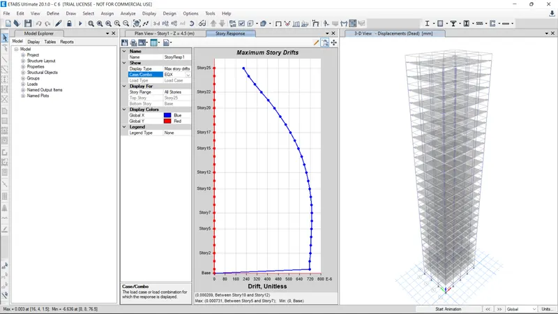
Base shear with no load factores means EQX and EQY only
Maximum storey drift in EQX = 0.00072.
storey drift shall not exceed 0.004*76.5 = 0.306 , Hence the condition satisfied.
Maximum storey drift in EQY = 0.0008.
storey drift shall not exceed 0.004*76.5 = 0.306 , Hence the condition satisfied.