MODELLING AND SIMULATION OF FLOW THROUGH A FLOW BENCH
AIM: To create a 3D model of a flow bench, run flow analysis and obtain a plot of lift vs mass flow rate.
AIR FLOW BENCH: It is a device used for testing the internal aerodynamic qualities of an engine component and is related to the more familiar wind tunnel. It is used primarily for testing the intake and exhaust ports of cylinder heads of I.C. engines. It is also used to test the flow capabilities of any component such as air filters, carburetors, manifolds or any other part that is required to flow gas. A flow bench is one of the primary tools of high performance engine builders, porting cylinder heads would be uncertain without it. The mass flow rate can be calculated using the known pressure and temperature data to calculate air densities, and multiplying by the volume flow rate.
FLOW BENCH DATA: The air flow bench can give a wealth of data about the characteristics of a cylinder head or whatever part is tested. The result of main interest is bulk flow. It is the volume of air that flows through the port in a given time. Expressed in cubic feet/min or cubic meters per second/min.
Valve lift can be expressed as an actual dimension in decimal inches or mm. It can also be specified as a ratio between a characteristic diameter and the lift L/D. Most often used is the valve head diameter. Normally engines have an L/D ratio from 0 up to a maximum of 0.35. For example, a 1” diameter valve would be lifted a maximum of 0.35”.
VALVE SEAT INSERTS: Valve seat inserts are representing a very important component of the valve train in I.C. engines, as they are the interface between the valve and the cylinder head. Valve and valve seat inserts together serve to seal off the combustion chamber regulating the inlet and exhaust gases. The valve seat insert avoid direct contact of the valve with cylinder head and absorbs part of the combustion heat which is transferred to the valve by passing it on to the cylinder head.
PROCEDURE:-
- Make cylinder with both diameter and length equal to 0.1 m.
- Sketch a path and profile for the inlet port. Using sweep command create an inlet port of diameter 0.02 m.
- Using shell command give thickness of 0.001 m to inlet port and cylinder.
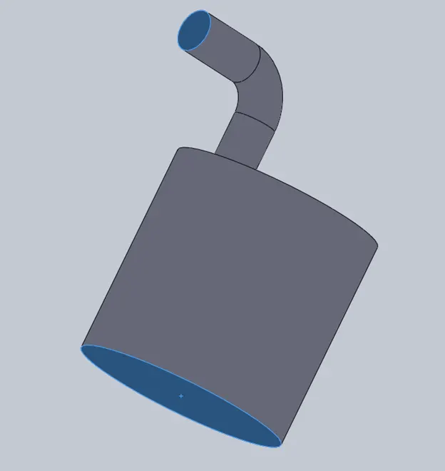
SHELL FACES
- Using reference geometry draw a plane to construct a valve seat insert in the port to seal the inlet port from the cylinder. Create a valve to match the valve seat insert.
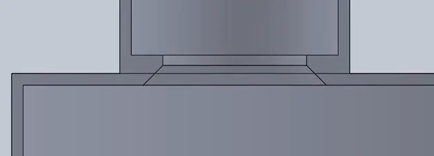
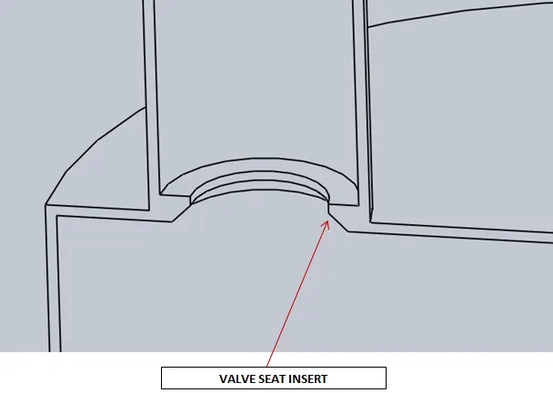
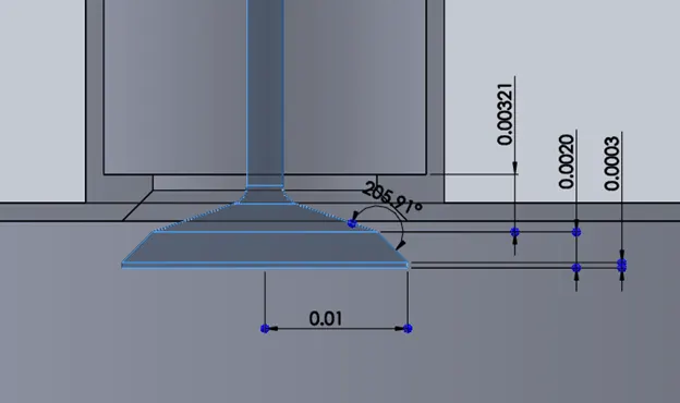
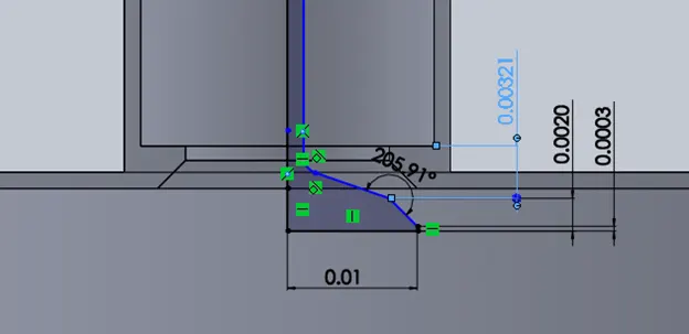
- Constrain the valve movement by dimensioning the valve entities so that the valve is able to move in only vertical direction during valve lift. Set a particular valve lift value (0.00321 m).
- Create lids on inlet port and cylinder.
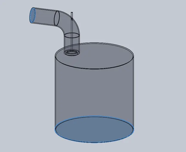
FLOWBENCH WITH LIDS
- Set up a wizard for steady state simulation for internal flow, selecting air as default fluid.
- Select inlet face of port for static pressure of 150 KPa and face of cylinder at lid for total pressure of 101.325 KPa for boundary conditions.
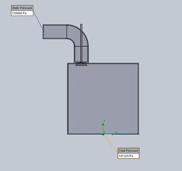
- Select mass flow rate for global goals and surface goals for the project. Select inlet face of port for surface goals.
- For global mesh select the level of automatic mesh and check advanced channel refinement for refining the cells at small surfaces.
- For local mesh select the faces and surfaces of valve and valve seat inserts and set the level of refining cells.
- Run the simulation. Create cut plots of pressure and velocity by selecting front plane when the solver is finished.
- After running the simulation change the level of global mesh at a particular valve lift to check mesh dependency of results such as pressure and velocity, mass flow rate.
- Select the best mesh and run a parametric study to show the effect of valve lift on mass flow rate.
COMPARISON OF GLOBAL MESH LEVELS AT VALVE LIFT OF 0.00321 m
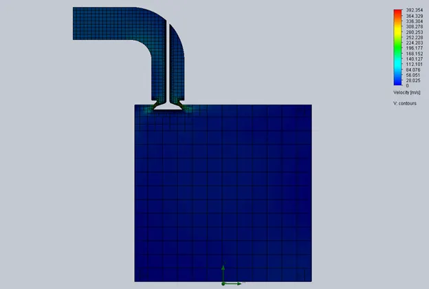
VELOCITY CUT PLOT AT GLOBAL MESH LEVEL 4
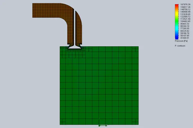
PRESSURE CUT PLOT AT GLOBAL MESH LEVEL 4
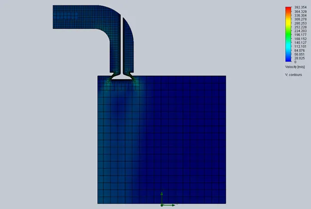
VELOCITY CUT PLOT AT GLOBAL MESH LEVEL 5
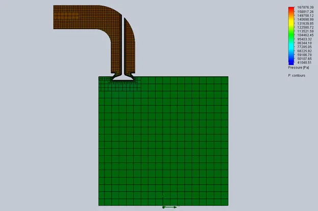
PRESSURE CUT PLOT AT GLOBAL MESH LEVEL 5
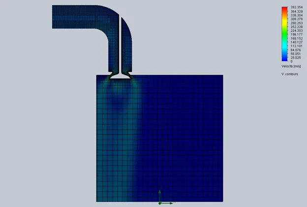
VELOCITY CUT PLOT AT GLOBAL MESH LEVEL 6
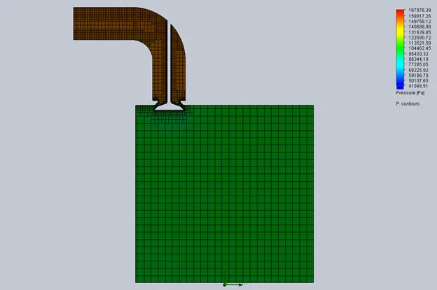
PRESSURE CUT PLOT AT GLOBAL MESH LEVEL 6
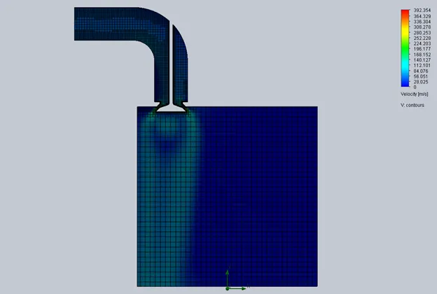
VELOCITY CUT PLOT AT GLOBAL MESH LEVEL 7
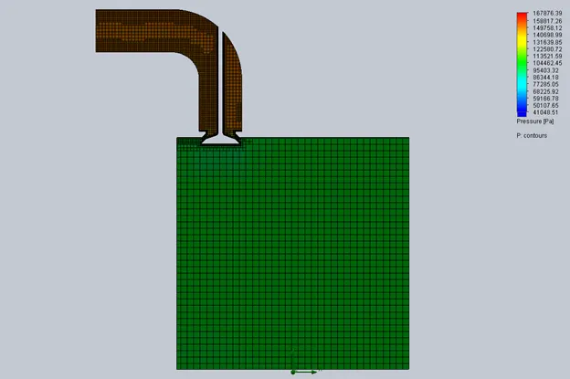
PRESSURE CUT PLOT AT GLOBAL MESH LEVEL 7
The above plots show that as we change the level of global mesh from coarse to fine we are getting different results. We can get a converged (constant) solution from a coarse mesh and a completely different converged solution for the same study using a fine mesh .With any simulation study we are looking to find a value where refining mesh does not give more accurate results. So, as the highest global mesh setting is 7, it is selected as the best mesh.
PARAMETRIC STUDY
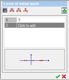
To run a parametric study, first of all select a dimension which changes the valve lift. In this case the dimension with value of 0.00321 m lifts the valve. Click edit sketch in which valve lift dimension is given, select the dimension and then go to add dimension parameter to add the dimension for valve lift. Exit the sketch.In variation type option select range with number to enter minimum and maximum values and number of values required to study valve lift. Now add other input variable i.e. global mesh at level 7 by clicking discrete values option. In output parameters add goals like SG mass flow rate etc. and cut plots of pressure and velocity. After adding all parameters and variables run the simulation.
RESULTS OF PARAMETRIC STUDY
CUT PLOTS
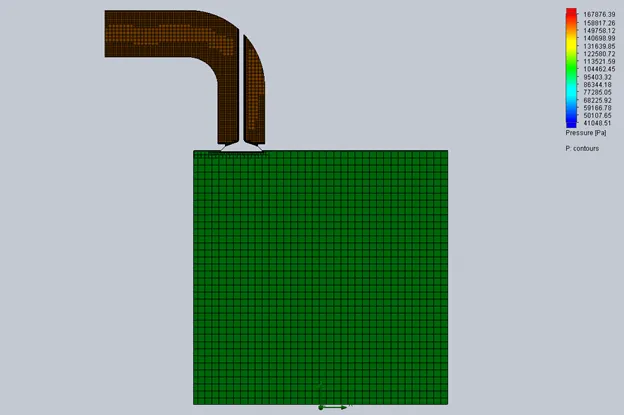
PRESSURE CUT PLOT AT VALVE LIFT EQUAL TO 0.00088 m
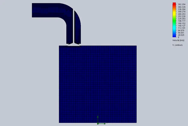
VELOCITY CUT PLOT AT VALVE LIFT EQUAL TO 0.00088 m
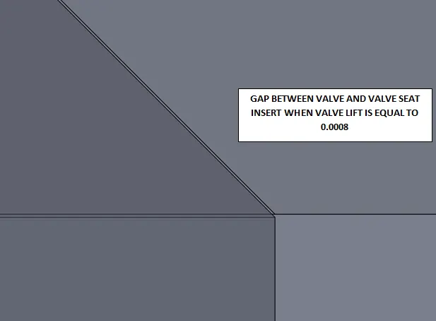
OBSERVATIONS: From the cut plots it is clear that since the valve is closed there is no change in pressure and velocity in the cylinder.
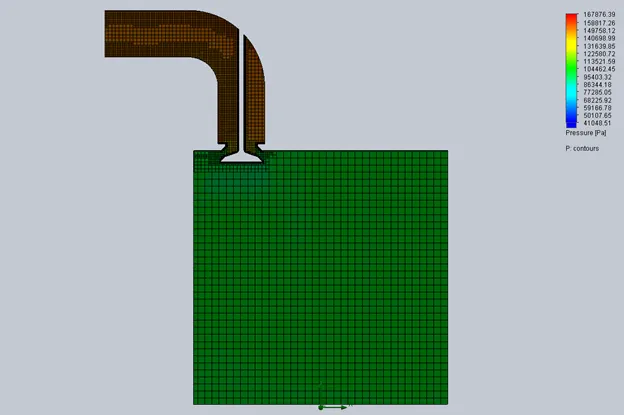
PRESSURE CUT PLOT AT VALVE LIFT EQUAL TO 0.0049 m
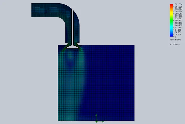
VELOCITY CUT PLOT AT VALVE LIFT EQUAL TO 0.0049 m
OBSERVATIONS: As the valve lifts to a value of 0.0049 m there is a drop in pressure near the valve inserts. The velocity in the cylinder starts increasing due to valve lift as air starts entering the cylinder.
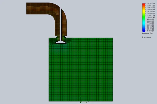
PRESSURE CUT PLOT AT VALVE LIFT EQUAL TO 0.009 m
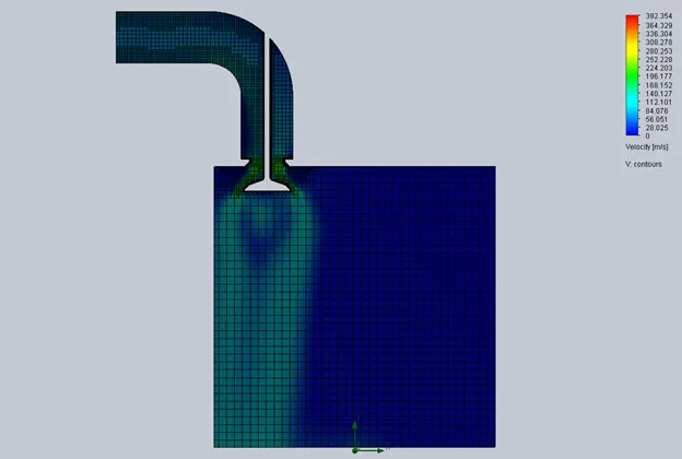
VELOCITY CUT PLOT AT VALVE LIFT EQUAL TO 0.009 m
OBSERVATIONS: Due to valve lift of 0.009 m there is more pressure drop near valve inserts and increase in velocity around the valve and valve inserts.
CONCLUSION: As the valve lift increases, the mass flow rate of air inside the cylinder also increases. We can take more values for valve lift in our study to see the plot variation.
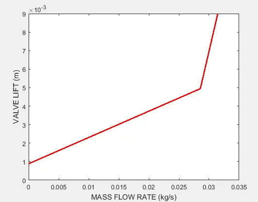
|
VALVE LIFT (m) |
MASS FLOW RATE (kg/s) |
|
0.000886 |
6.00248E-09 |
|
0.004943 |
0.028556421 |
|
0.009 |
0.031457295 |
REFERENCES:-
- WIKIPEDIA
- FEDERAL MOGUL
- SOLID SOLUTIONS UK