Mobile Drop Test Simulation using LS-DYNA
Objective: Perform Mobile Drop Test Simulation using LS-DYNA and write a detailed report explaining the results obtained.
Question:
In this assignment, we provide you with a file having just nodes and elements of two parts, a simplified cellphone and a plate mimicking ground.
You need to create a complete simulation file from this to perform a drop test. *INITIAL_VELOCITY card is to be used to give velocity specifications for the cellphone.
We are not interested in how the phone travels from your hand to the plate, but only the period when the impact happens and a few milliseconds after that. Therefore, we will keep the two parts very close and provide an appropriate magnitude of velocity.
The orientation of the cellphone is also important and there are specific guidelines on how to orient the products but for this assignment, we will ignore that.
Based on what you have learned till now, use your judgment, manuals, and the previous simulations that are shown to create a complete input file for a drop test.
The objective of this assignment is not to get a correct simulation but to get a feel of creating an input deck from scratch.
Case Setup and Execution:
Open the given keyword file in LS PrePost.
Geometry:
The input file consists of three different parts
1. Mobile of solid elements
2. Bottom Plate of solid elements
3. Bottom Plate of Shell elements
So either bottom plate of solid or shell elements can be considered for simulation.
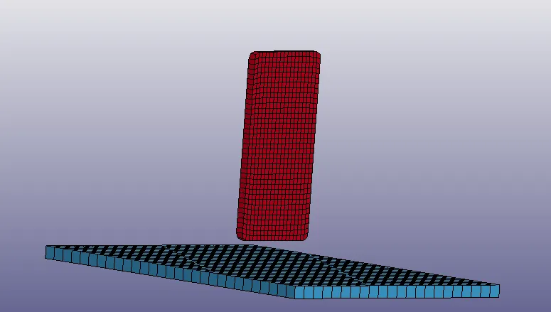
So for this simulation, mobile and bottom part of solid elements are considered and the bottom plate with shell elements is deleted.
Material:
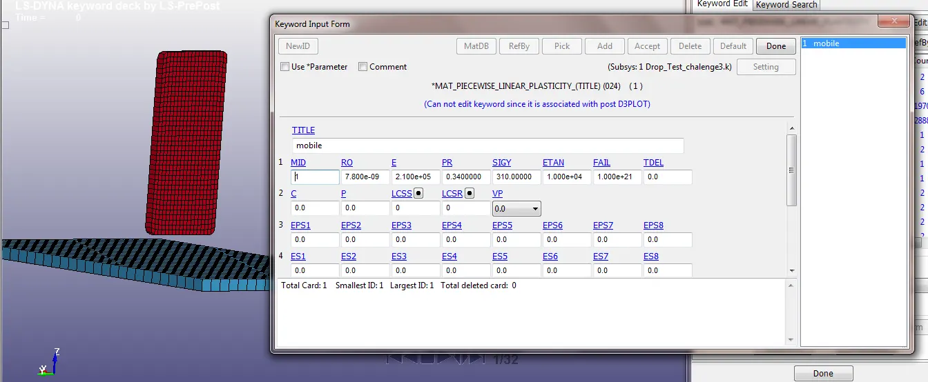
For Mobile 'MAT-24-Piecewise_Linear_Plasticity' material card is defined with material id 1.
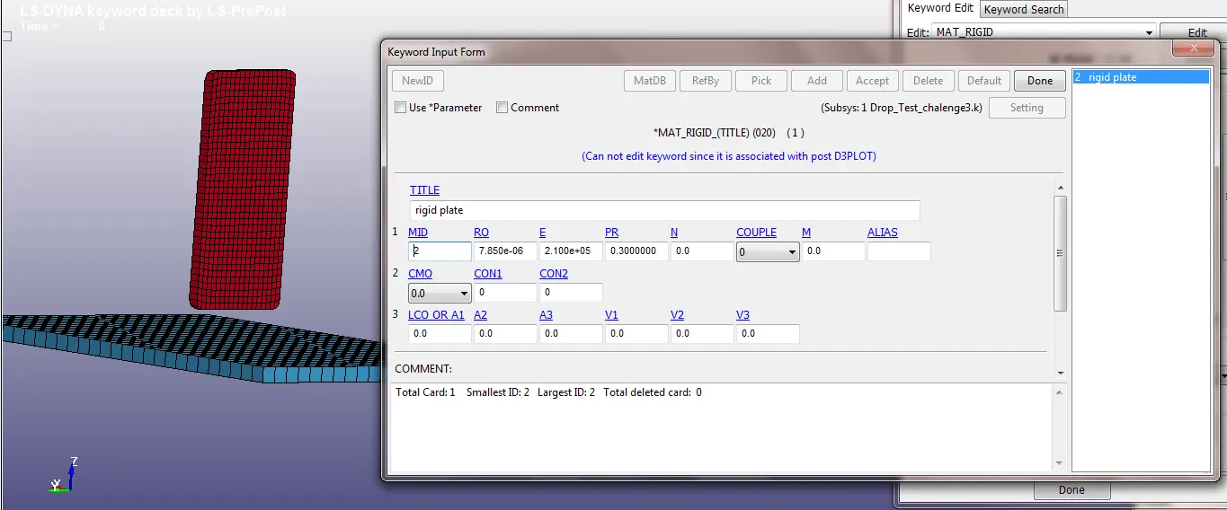
For Bottom Plate 'MAT-20-Rigid' material card is defined with material id 2.
Section:
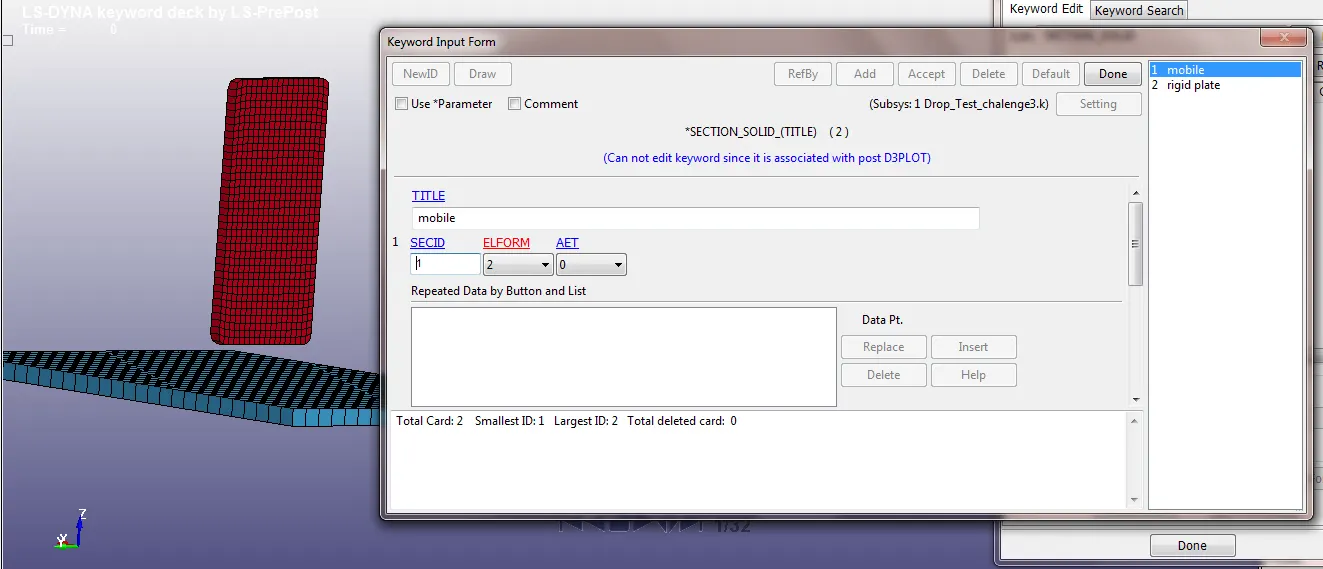
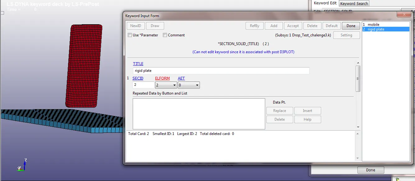
'Section_Solid' card has been created for both mobile and bottom plate.
Part Keyword assignment:
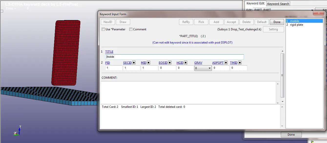
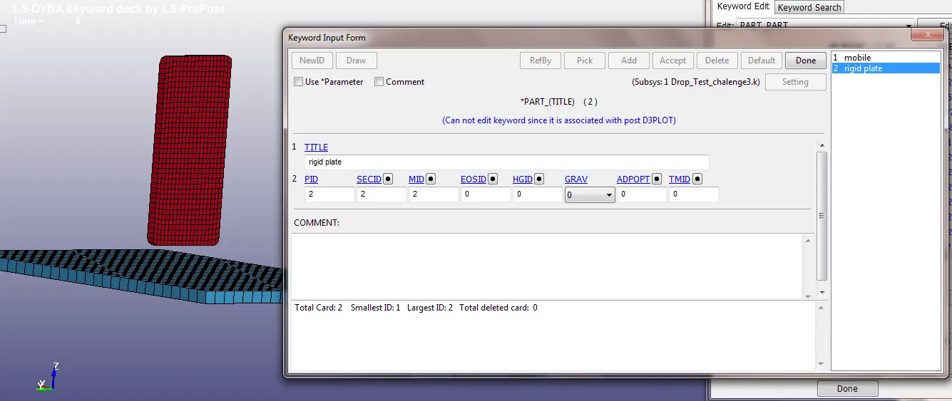
Now assign the created material and section keywords to their respective parts.
Boundary Conditions:
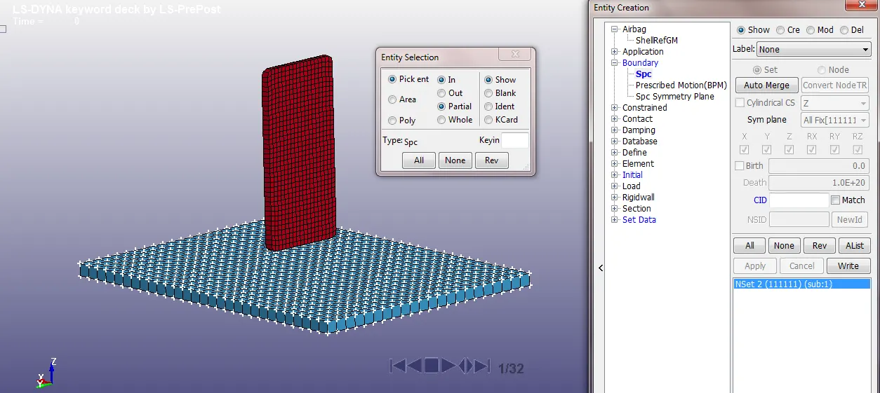
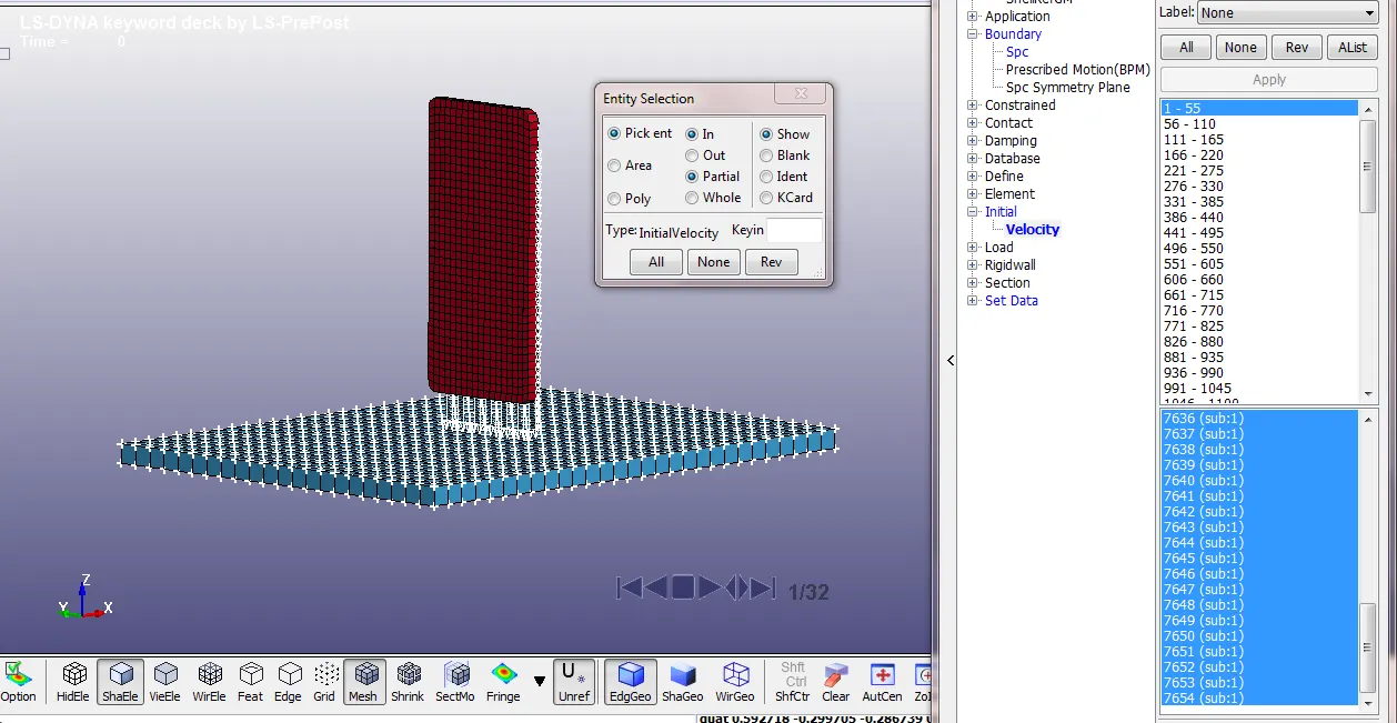
The bottom rigid plate is fixed by constraining the boundary elements of the plate in all degrees of freedom using the keyword 'Boundary_Spc' (Single Point Constraint).
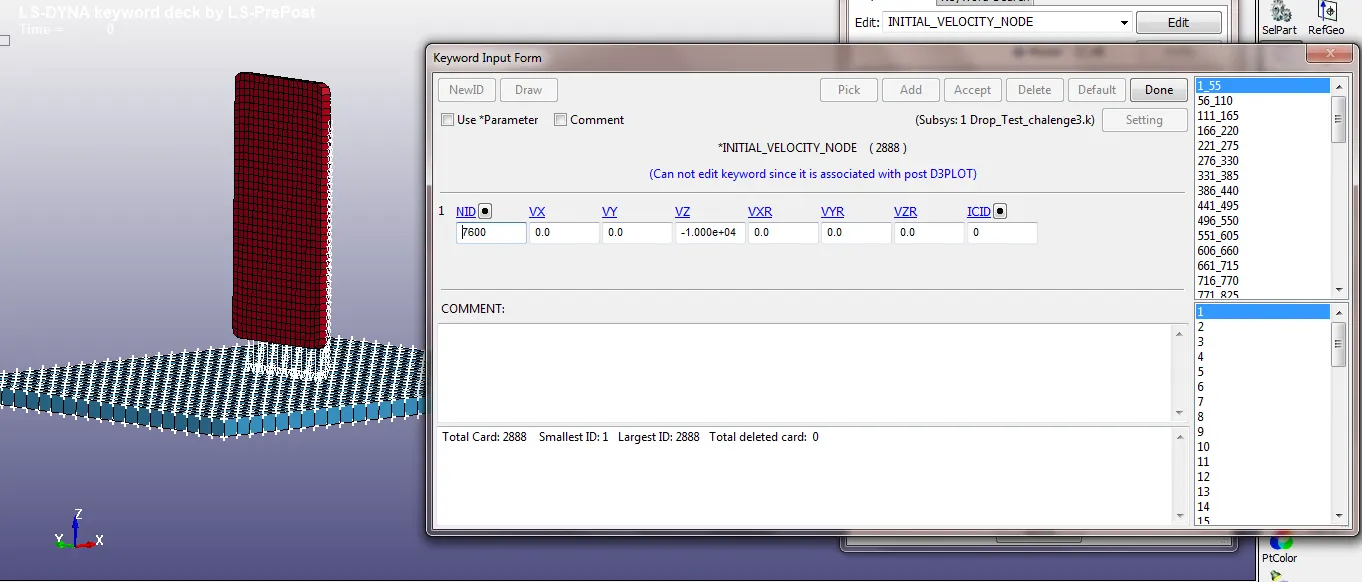
Initial Velocity of 10000mm/s is applied in -ve z direction to mobile using 'INITIAL_VELOCITY_NODE' keyword
Contact:
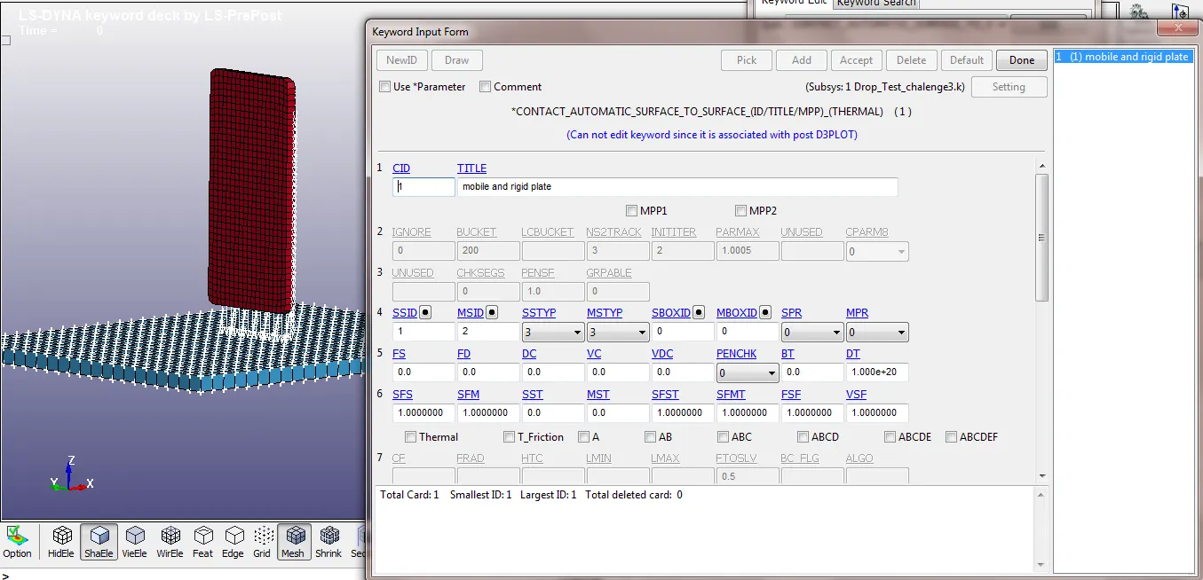
Contact between mobile and rigid plate is created using 'CONTACT_AUTOMATIC_SURFACE_TO_SURFACE' keyword and is defined using part ID with mobile being the slave and rigid plate as master.
Controls:
Energy:
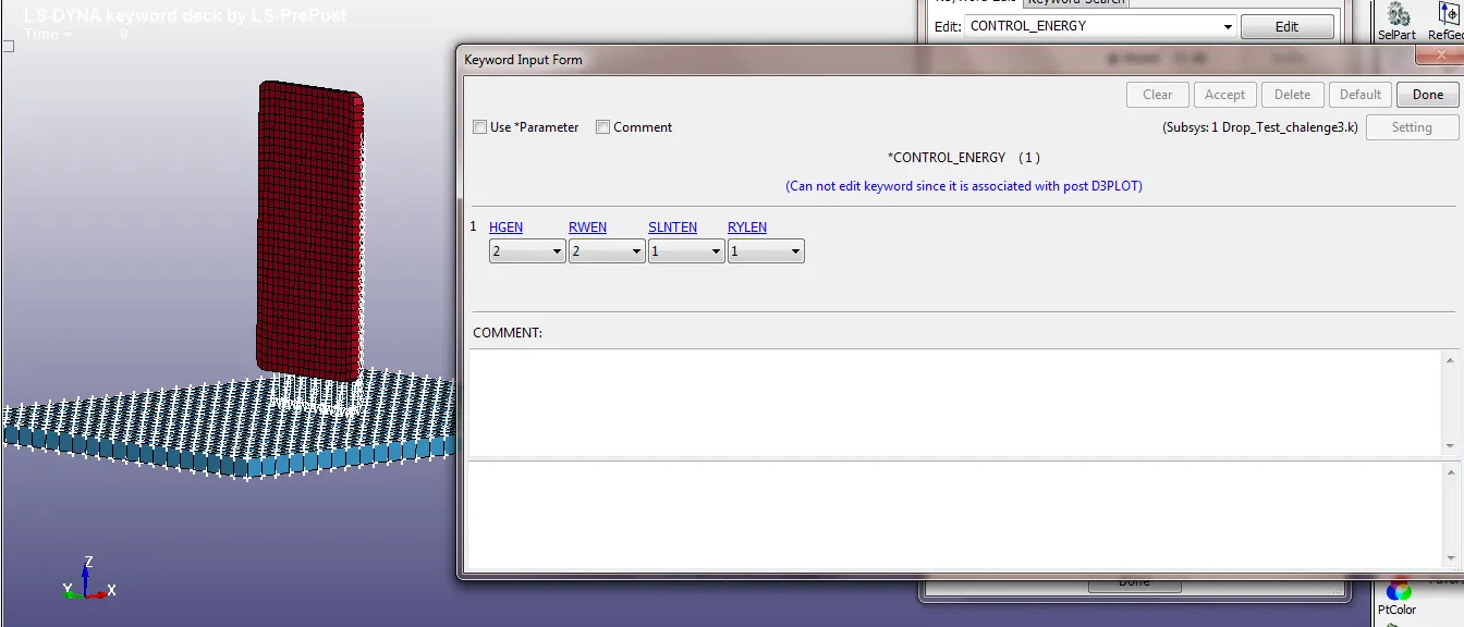
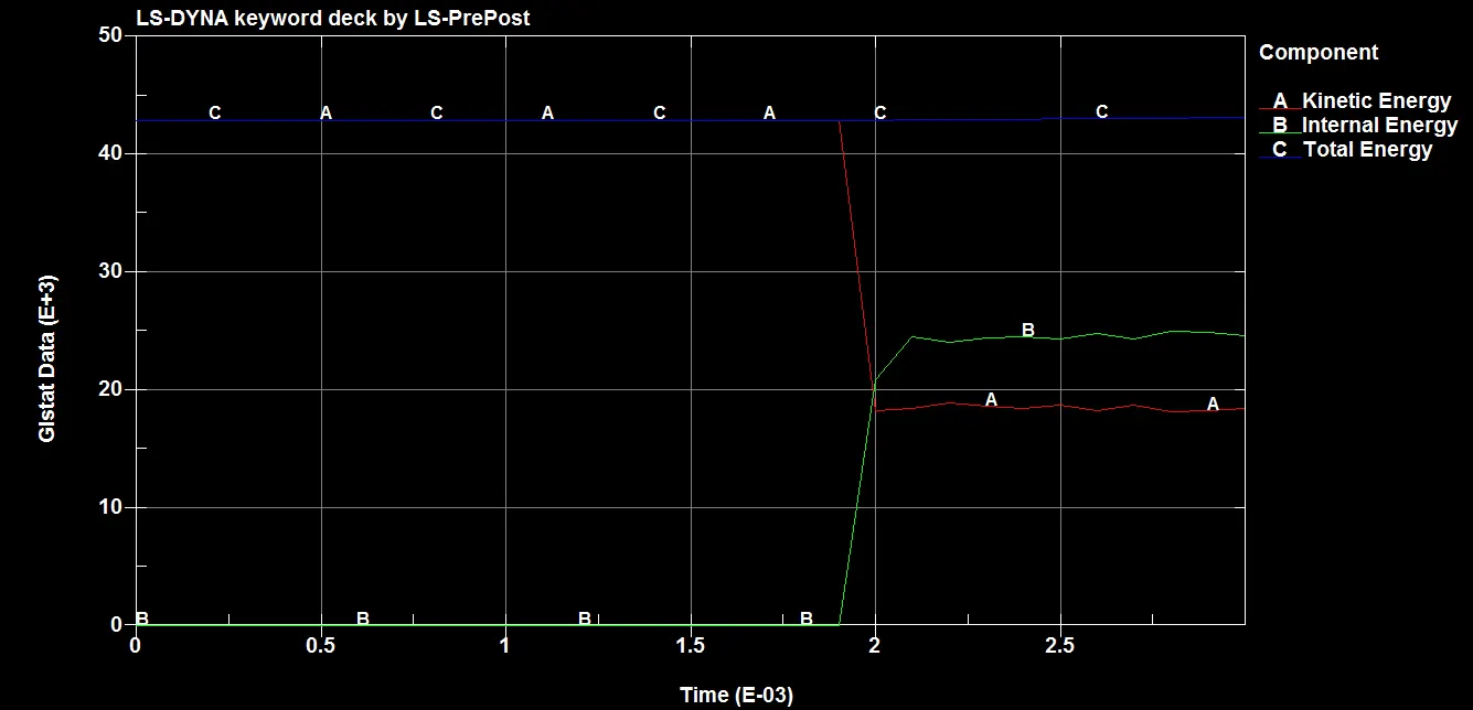
'CONTROL_ENERGY' keyword has been created to get outputs like hourglass energy, sliding interface energy etc.
Termination:
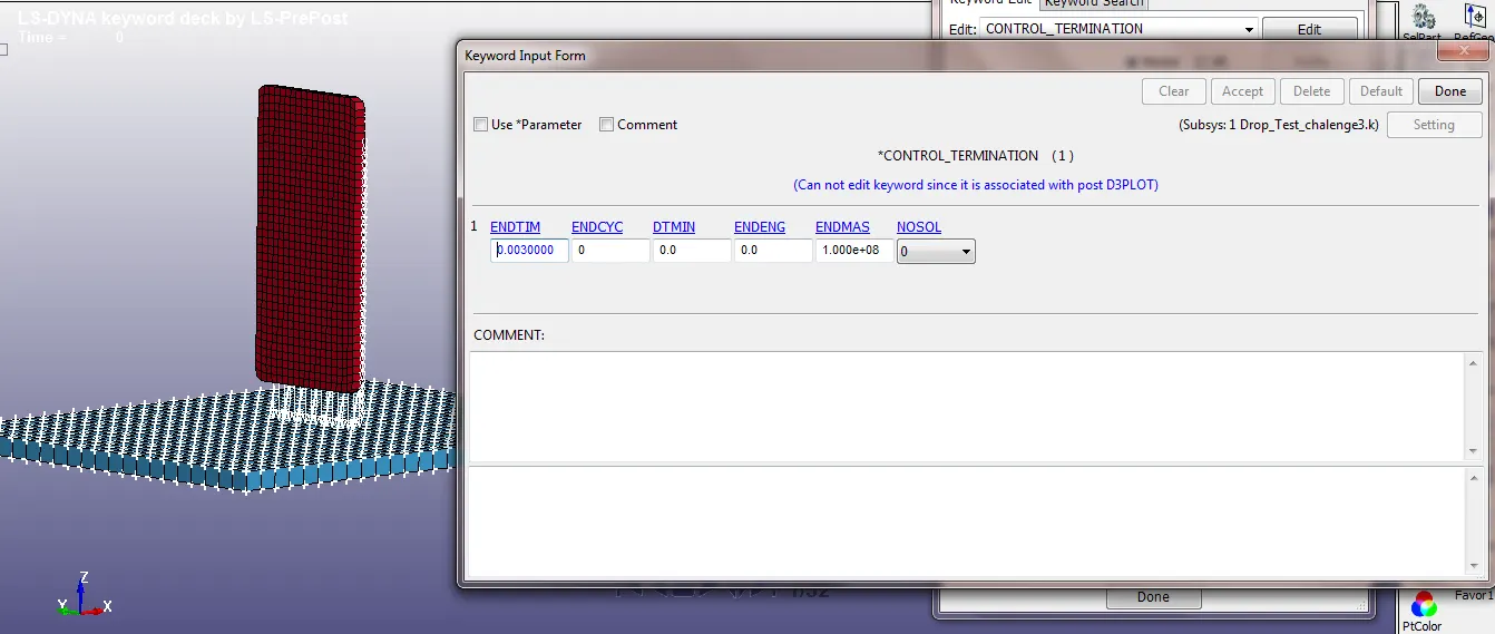
The termination time for the problem is defined using 'CONTROL_TERMINATION' keyword. The distance between the mobile and bottom plate is calculated and approximate time is taken (0.003s), so that the impact and some additional time after the impact can be simulated.
Database:
'DATABASE_BINARY_D3PLOT' keyword is defined which gives animation and other post-processing data after simulation.
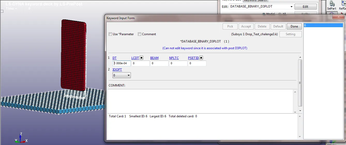
'ASCII_OPTION' keyword is created with same time interval.
1. ELOUT- Element Data
2. GLSTAT- Global Data
3. MATSUM- Material Energies
4. RCFORC- Contact Interface forces
5. SLEOUT- Sliding interface energies
Model-Check:
Check the model using model checker and make sure the model is error free.
Solving:
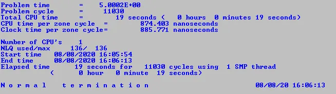
Save the keyword, run the file in LS-DYNA Program manager and if the solver ends as normal termination then the model is correct.
Post-Processing (Results):
VonMises Stress:
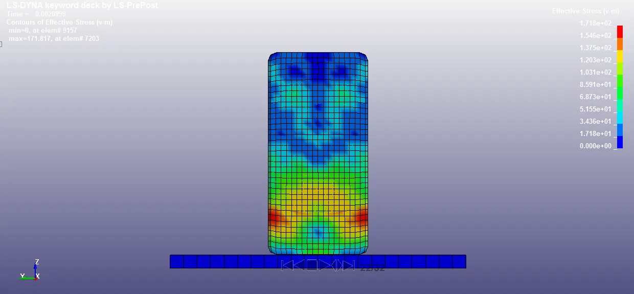
Following contours show effective stress after the impact.
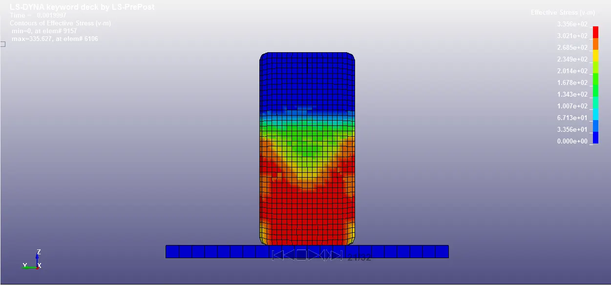
In the above figure, we can observe that high stress value in the lower part of the mobile just after the impact.
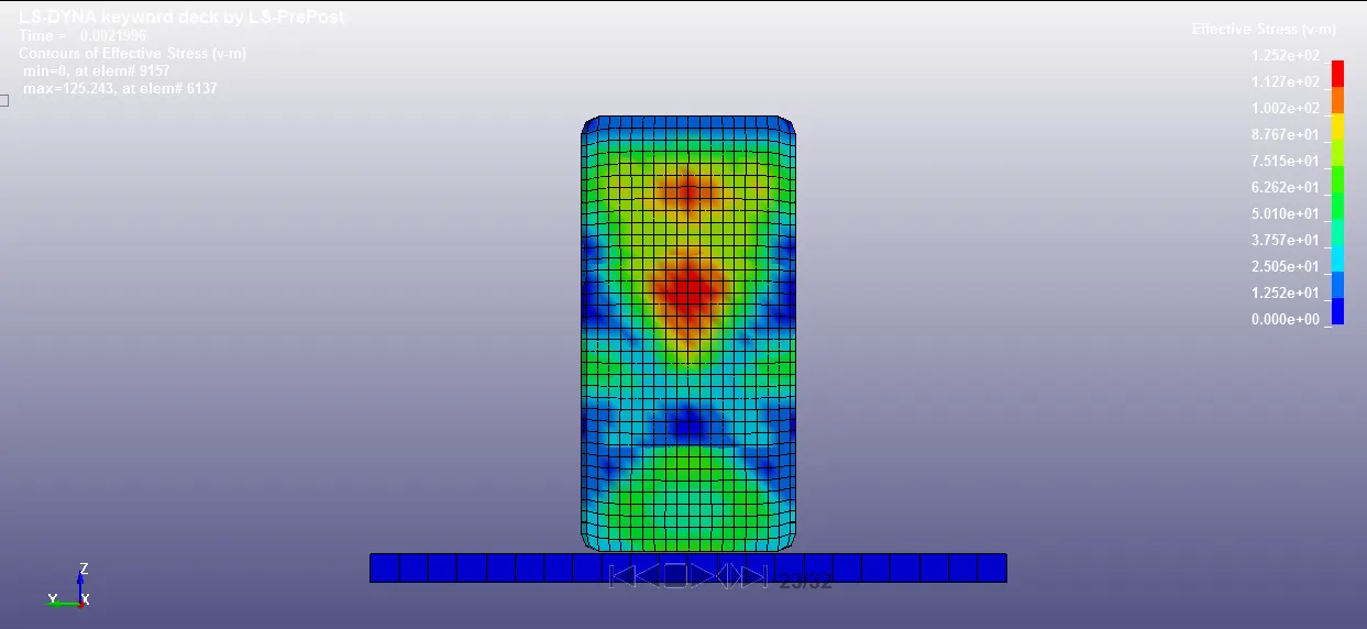
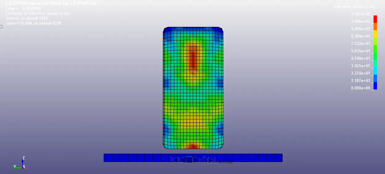
In the below figures, we cam observe the stress propagation throught the mobile body due to impact at different time intervals.
Energy Plots:
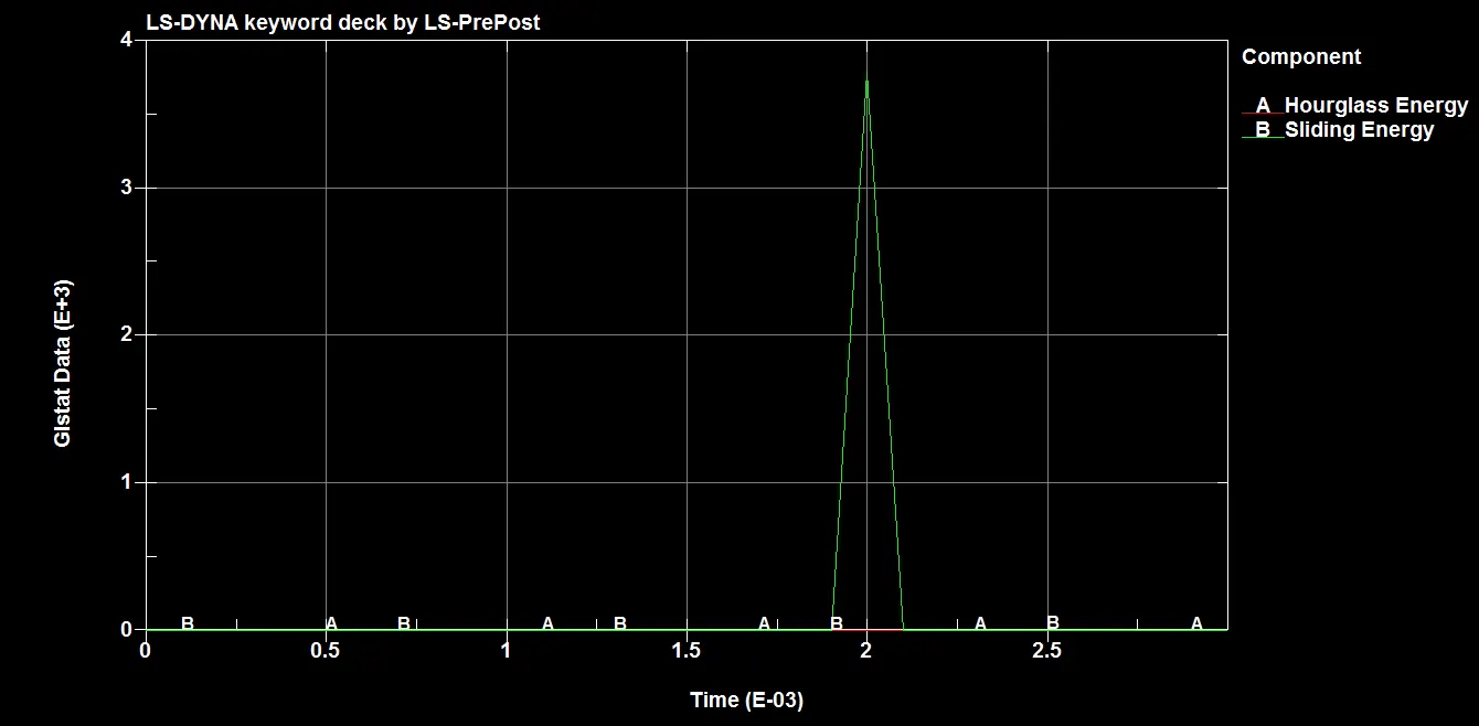
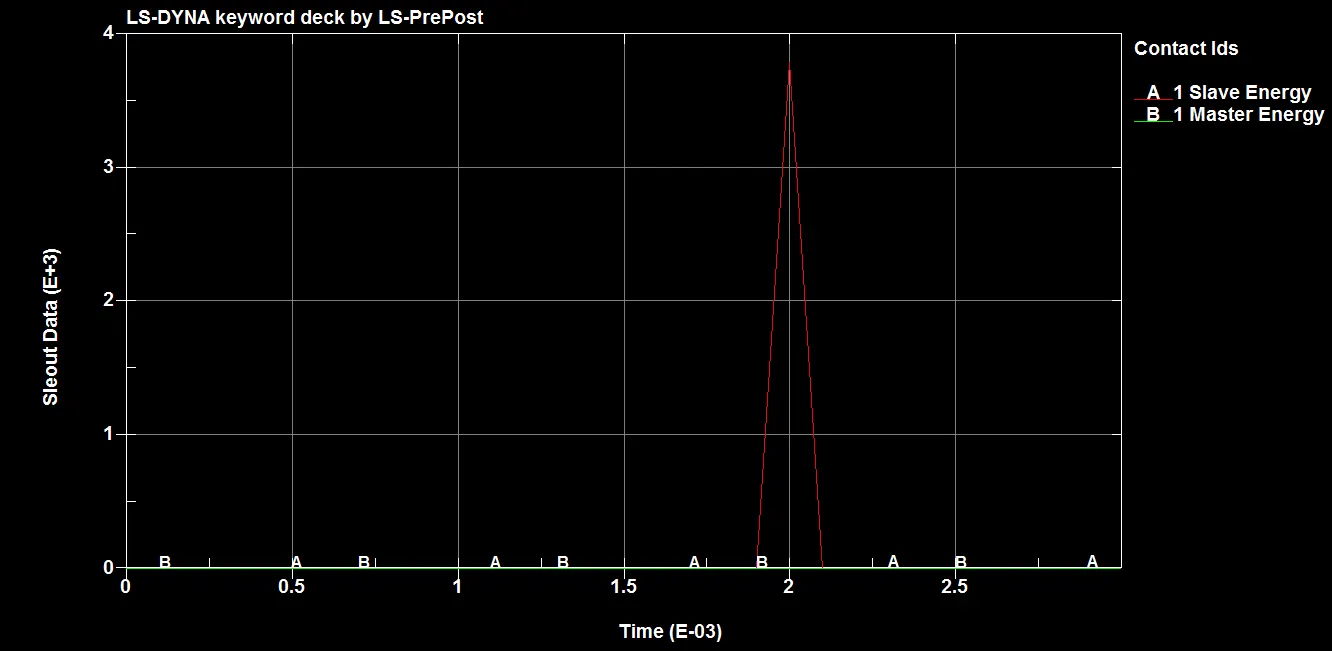
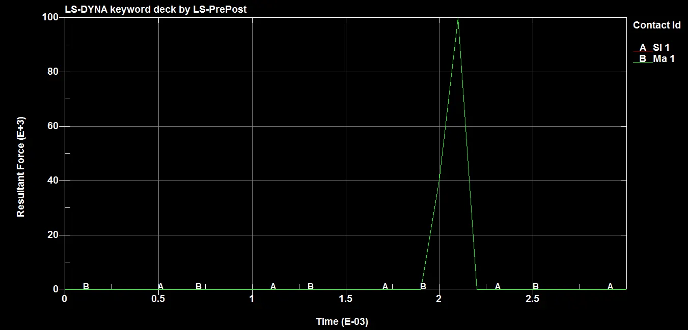
Conclusion:
- The drop test simulation of mobile is successfully completed in LS-DYNA and results like energy plots, stress contours etc are extracted.