MBD Simulation on IC Engine Valve Train
IC ENGINE VALVE TRAIN MOTION ANALYSIS (MBD)
AIM
To create MBD Simulation on IC Engine Valve Train and analyse the result.
INTRODUCTION
Valve trains are an important part of a 4 stroke IC engine as it determines when the air/fuel charge should enter the combustion chamber as well as when the burnt gas goes out.
Valve trains can be classified as
- OHV (Over Head Valve; eg. old Royal Enfield engine)
- SOHC/DOHC (single/Double Over Head Cam; eg. Bajaj Dominar 400)
- Camless (use Electromechanical actuators; eg. Koenigsegg Gamera freevalve engine)
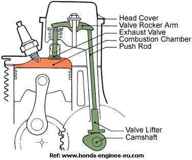
In this project, we’ll be designing OHV. here, the camshaft will be inside the engine block and pushrod transfers the motion to rocker arm which actuates the respective valve.
credits:https://medium.com/@thecwetz/overhead-valve-v8s-bfce9175620
It contains mainly
- Camshaft with cam - This shaft, driven by crankshaft either by gears or chain drive will rotate at a speed lesser than crankshaft (usually half the speed of crankshaft) contains cams. These cams have a peculiar shape that contacts the pushrod, enabling the system to push the push rod for specific time period alone in one rotation of the camshaft.
- Pushrod - The rod that’s in contact with cam and rocker arm one end. When cam pushes the push rod, the pushrod pushes the rocker arm.
- Rocker arm - This part is like a centrally hinged part(like see saw). When the pushrod pushes its one end upside, this pushes the valve downside on the other end.
- Valve - This part makes the chamber sealed during combustion. Also lets in and out gases. The size of its face determines volumetric efficiency of an engine cylinder (inlet valve). When the rocker arm pushes the valve, the valve goes into the chamber, creating space for gases to let in/out of the cylinder.
- Valve guide - This is mounted on the cylinder head. Above this spring will be provided. This guide valve in and out without lateral movement.
Working: The principle is cam's design which, when rotating, nose part of it comes to contact with pushrod it starts to push it, which in turn push rocker arm's one end (which hinged at center). Eventually, from other side rocker arm pushes the valve into chamber allowing gases to go inside or come outside of chamber. Due to spring force from valve spring between valve and valve guide valve comes to original position when nose part isn't contact with pushrod.
The valve movement i.e, how much it goes inside is determined by cam design. This property also determines volumetric efficiency of an engine cylinder (inlet valve).
This analysis will be usful for selecting materials based on maximum force we use, to reduce weight if unwanted material is more on nocontact place. Also used to reduce friction by finding correct oil for lubrication based on friction force from analysis. Space requirements can be found with this analysis.
FORMULA
Cam design
Our cam has 2 circles with dimension D1 = 35mm and D2 = 20 mm
For 3.5mm lift
L = lift - R2 + R1 = 3.5 - 10 +17.5 = 11mm
For 6mm lift
L = lift - R2 + R1 = 6 - 10 +17.5 = 13.5mm
3D MODEL
Cam for 3.5 mm lift
Cam for 6 mm lift
Pushrod
Rocker arm
Valve
Valve guide
Assembly
MATES:
- Each part's front plane coincided with assembly front plane.
- Axis of rocker arm mated with assembly top plane and right plane.
- Distance mate between cam axis and assembly top plane (130 mm).
- Distance mate between cam axis and assembly right plane (20 mm).
- Distance mate between pushrod axis and assembly right plane (20 mm).
- Distance mate between valve guide axis and assembly top plane (60 mm).
- Distance mate between valve guide axis and assembly right plane (50 mm).
- Coincide mate for valve axis and valve guide axis.
Apply cast carbon steel as material for whole parts.
LINK for files: https://drive.google.com/drive/folders/1NfLxF98YSLsPZio-xJjBKBw7GtwEtTPj?usp=sharing (in case, part missing error arises, use zip file content)
MOTION ANALYSIS
- Enter solidworks motion.
- Select motion analysis.
- Select rotary type motor with constant speed 1500RPM for cam axis.
- Choose contacts with steel(dry) between: i) Cam and pushrod; ii) Pushrod and rocker arm; iii) Rocker arm and valve;
- Provide linear spring between valve guide face and valve with 20N/mm spring constant and 35mm distance.
- In motion property, select (1500*6 = 9000fps) and precise contact.
LINK for animation: https://drive.google.com/drive/folders/1NfLxF98YSLsPZio-xJjBKBw7GtwEtTPj?usp=sharing (download and watch as it is mp4(compressed))
RESULT
For 3.5mm lift
Valve lift
Contact forces
1. Cam and pushrod
2. Pushrod and rocker arm
3. Rocker Arm and valve (magnitude)
4. Rocker Arm and valve in x-direction
For 6mm lift
Valve lift
Contact forces
1. Cam and pushrod
2. Pushrod and rocker arm
3. Rocker Arm and valve (magnitude)
4. Rocker Arm and valve in x-direction
CONCLUSION
- From valve lift graph, it is clear that during dweel period the displacement is very less (fluctuating for ~0.05mm) and once nose partcomen to contact linear displacement reaches its peak based on lift designed for cam (53-50mm) and then comes to initial postion once heal part of cam started and hence dwell period started according to cam design.
- Contact force between pushrod and rocker arm and cam and pushrod increases as lift increases. It is worth to mention that the spring constant value is 20N/mm, so more force required to push per mm compared to10N/mm or 15N/mm. Also if you see contact force is maximum for these when valve is at its lowest position.
- Contact force between rocker arm and valve is nearly same for both the cases due to prescence of 20Nm stiffness spring. Here too, the contact force is peak once valve reaches its bottom most point.
- Why the contact force between the Rocker arm and valve varies while measuring with respect to the X direction and measuring with respect to magnitude? If we compare x-direction value and magnitude value of contact force between valve and rocker arm, there is difference beacause magnitude is net resultant force of all direction of forces (friction, push from cam rotation etc) but the x direction force only indicates friction force between 2 components here. Also later shows negative forces as first rocker arm comes towards the origin(pressing down) and later it goes away from valve origin(going up).