MBD SIMULATION ON IC ENGINE VALVE TRAIN
AIM: MBD Simulation on IC Engine Valve Train with cam lift 3.5 mm and 6 mm at 1500 rpm.
VALVE TRAIN: A valve train is a mechanical system that controls operation of the intake and exhaust valves in an internal combustion engine.
CAM: A cam is a rotating or sliding piece in mechanical linkage used especially in transforming rotary motion into linear motion. It is often a part of a rotating wheel or shaft that strikes a lever at one or more points on its circular path.
PUSHRODS: Pushrods are long, slender metal rods that are used in overhead valve engines to transfer motion from camshaft to the valves.
ROCKER ARM: A rocker arm is an oscillating lever that conveys radial movement from the cam lobe into linear movement at the poppet valve (valve typically used to control the timing and quantity of gas or vapor flow into an engine) to open it.
VALVE: A valve is a device that regulates, directs or controls the flow of fluid by opening, closing, or partially obstructing various passageways.
FREE LENGTH OF SPRING: The actual length of a compression spring without any sort of load or force being placed on it.
SLENDERNESS RATIO: If a compression spring’s free length is too long in proportion to its diameter, it is going to bend/buckle. This is referred to as the Slenderness Ratio.
PROCEDURE:-
- Make 3D models of cam, pushrod, rocker arm, valve and valve mount from the given drawings. Create sketch of cam so that the cam lift is equal to 3.5 mm.
CAM LIFT FORMULA = (L-R1) +R2
L = Distance between centers of two circles
R1 = Radius of lower circle of cam
R2 = Radius of upper circle of cam
- Open assembly to assemble the parts.
- Make the axis of rocker arm and right plane of assembly coincident.
- Make the axis of rocker arm and top plane of assembly coincident.
- Make front plane of rocker arm and front plane of assembly coincident.
- Make front plane of cam and front plane of assembly coincident.
- Make the axis of pushrod and front plane of assembly coincident.
- Make the axis of valve and front plane of assembly coincident.
- Make the axis of valve mount and front plane of assembly coincident.
- Apply distance constraint between axis of pushrod and right plane of assembly. Enter a distance of 20 mm.
- Similarly, enter a distance of 20 mm between the central axis of cam and right plane of assembly.
- Enter a distance of 50 mm between axis of valve mount and right plane of assembly.
- Enter a distance of 60 mm between top face of valve mount and top plane of assembly.
- Make the axis of valve and valve mount coincident.
- Apply distance constraint between the central axis of cam and top plane. Enter a value of 125 mm.
- Go to move component and check physical dynamics option. Drag a part until all parts are touching each other. Click OK.
- Go to motion analysis. Select central axis of cam for motor.
- Select all the components which are in contact with each other as a pair in contact option. Select steel (dry) in material option.
- Go to spring and select the edge of valve and top edge of valve mount between which the spring will be placed. Enter 25 N/ mm spring constant and 45 mm free length.
- Edit the material of cam, pushrod, rocker arm, valve and valve mount to plain carbon steel.
- Go to settings and enter frames per second to a value of 9000. Check use precise contact option.
- Set the motion analysis time to 1 s by dragging end time.
- Click on calculate motion study to run the analysis.
- Go to results and plots to insert graphs. Select bottom face of valve to create linear displacement graph of valve.
- Select circular face of cam and bottom face of pushrod to create graph of reaction force between cam and pushrod.
- Similarly, select contact faces of parts to create plots of other parts. Select X component instead of magnitude in result component to create plot of reaction force between rocker arm and valve.
- Repeat the above steps to do the simulation of cam with cam lift equal to 6 mm.
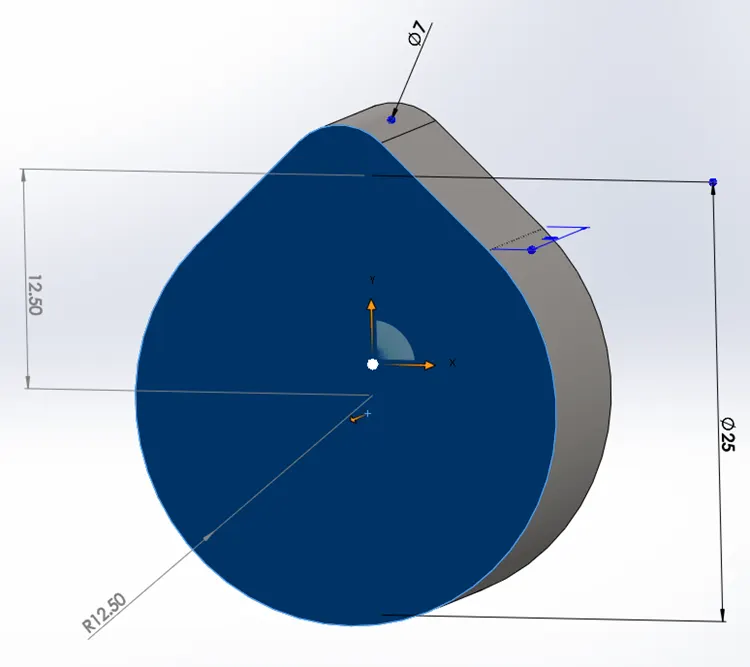
CAM WITH CAM LIFT 3.5 mm
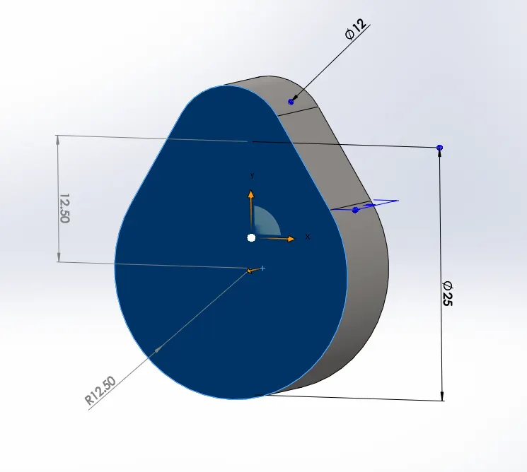
CAM WITH CAM LIFT 6 mm
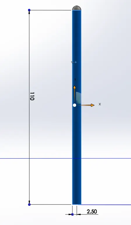
PUSHROD
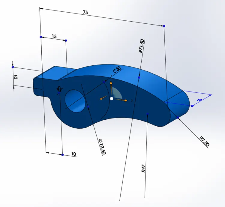
ROCKER ARM
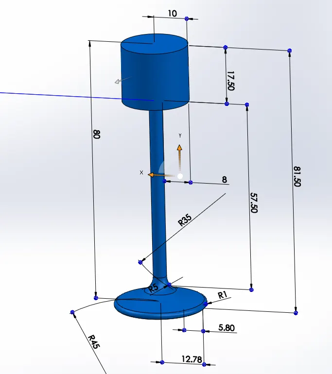
VALVE
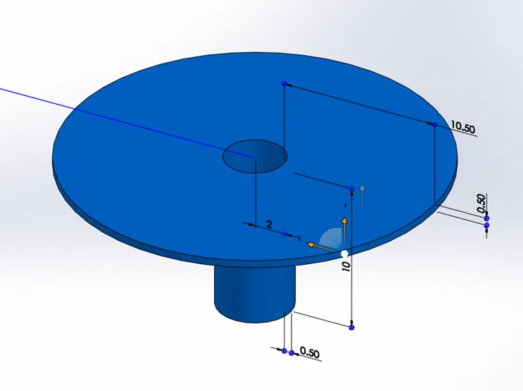
VALVE MOUNT
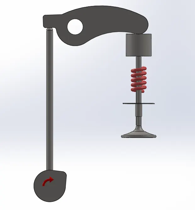
IC ENGINE VALVE TRAIN ASSEMBLY WITH CAM LIFT EQUAL TO 3.5 mm
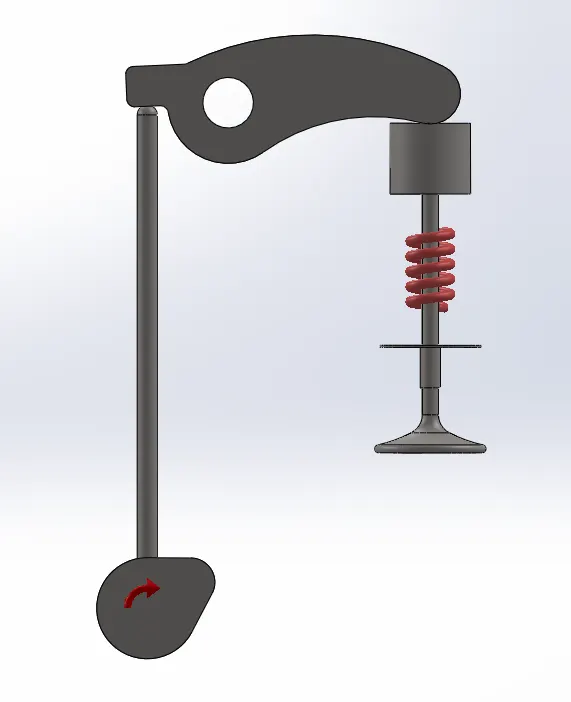
IC ENGINE VALVE TRAIN ASSEMBLY WITH CAM LIFT EQUAL TO 6 mm
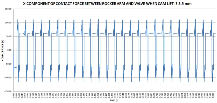
SIMULATION OF IC ENGINE VALVE TRAIN ASSEMBLY WHEN CAM LIFT IS 3.5 mm
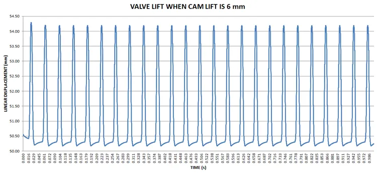
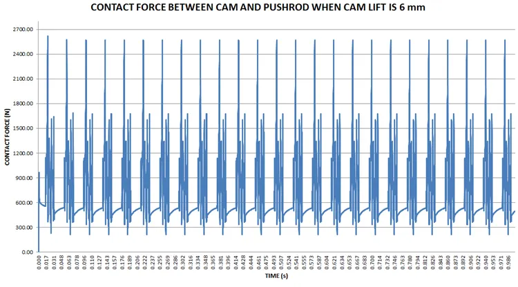
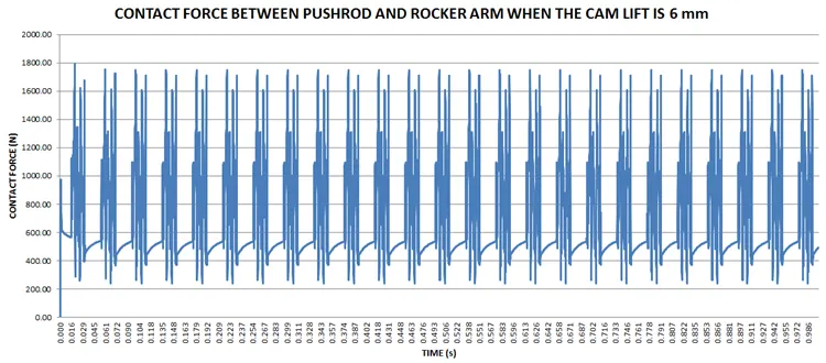
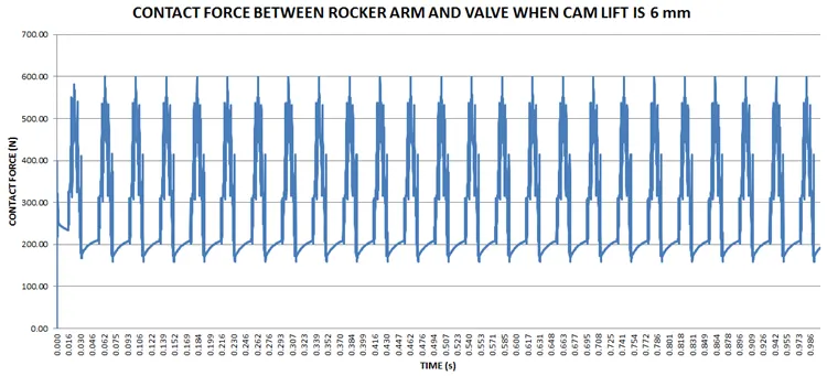
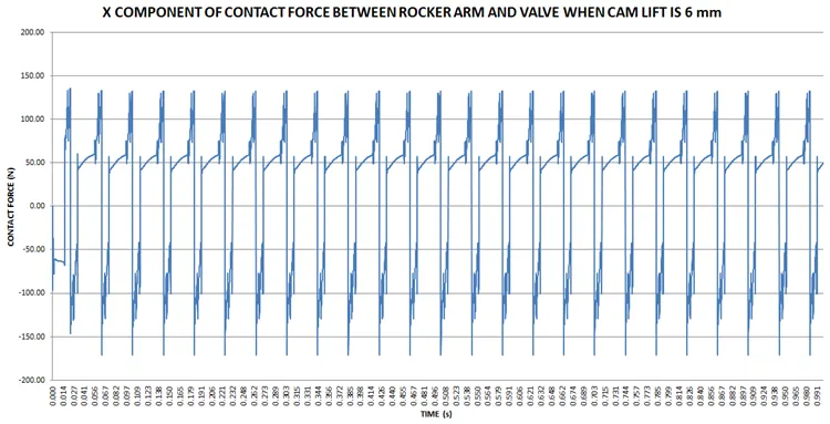
SIMULATION OF IC ENGINE VALVE TRAIN ASSEMBLY WHEN CAM LIFT IS 6 mm
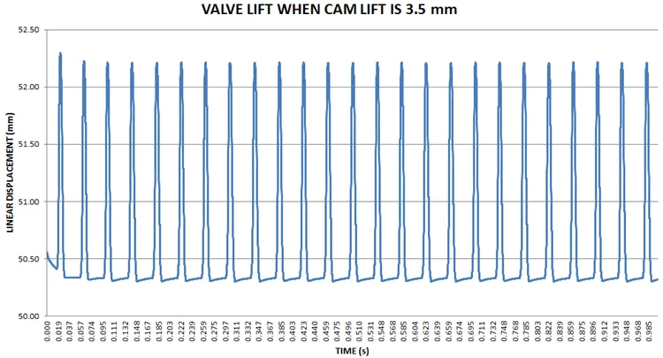
OBSERVATIONS: The above plots and data of valve lift show that the maximum valve lift is 52.30 mm at t = 0.023 s when the cam lift is 3.5 mm and the minimum valve lift is 50.30 mm at t = 0.110 s. When the cam lift is 6 mm, the maximum valve lift is 54.29 mm at t = 0.023 s and the minimum valve lift is 50.17 mm at t = 0.071 s.
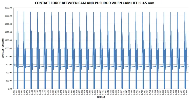
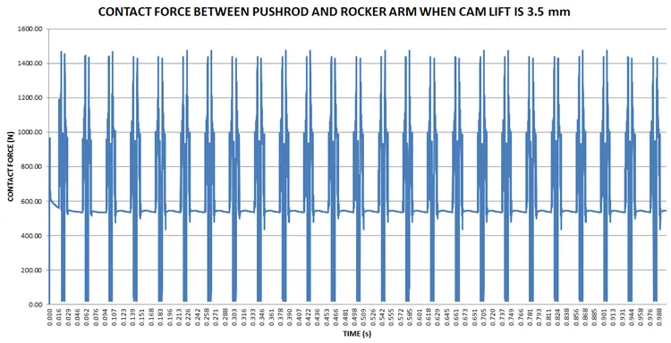
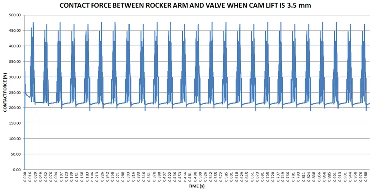
Following observations were made between the contact parts when the cam lift was 3.5 mm and 6 mm respectively:-
|
CONTACT PARTS |
CAM LIFT (mm) |
MAX. CONTACT FORCE (N), AT TIME (s) |
MIN. CONTACT FORCE (N), AT TIME (s) |
|
CAM AND PUSHROD |
3.5 |
1925.68, 0.021 |
ZERO, ZERO |
|
PUSHROD AND ROCKER ARM |
3.5 |
1472.82, 0.265 |
ZERO, ZERO |
|
ROCKER ARM AND VALVE |
3.5 |
476.69, 0.265 |
ZERO, ZERO |
|
CONTACT PARTS |
CAM LIFT (mm) |
MAX. CONTACT FORCE (N), AT TIME (s) |
MIN. CONTACT FORCE (N), AT TIME (s) |
|
CAM AND PUSHROD |
6 |
2617.71, 0.020 |
ZERO, ZERO |
|
PUSHROD AND ROCKER ARM |
6 |
1791.85, 0.020 |
ZERO, ZERO |
|
ROCKER ARM AND VALVE |
6 |
600.79, 0.063 |
ZERO, ZERO |
Following observations were made between the contact parts rocker arm and valve when x-component of contact force was selected:-
|
CAM LIFT (mm) |
MAX. POSITIVE (UPWARD) CONTACT FORCE (N), AT TIME (s) |
MAX. NEGATIVE (DOWNWARD CONTACT FORCE (N), AT TIME (s) |
|
3.5 |
113.77, 0.263 |
-117.06, 0.023 |
|
6 |
135.45, 0.023 |
-171.45, 0.183 |
The above graphs and data show that there is a variation in the graphs of rocker arm and valve when x-component of contact force is selected and when only magnitude of contact force is selected.
CONCLUSIONS: The maximum value of valve lift increases from 52.30 mm to 54.29 mm at 0.023 s when cam lift increases from 3.5 mm to 6 mm. There is also a change in minimum value of valve lift from 50.30 mm at 0.110 s to 50.17 s at 0.071 s when cam lift increases from 3.5 mm to 6 mm.
There is also an increase in max. contact force between the contact parts when cam lift increases from 3.5 mm to 6 mm.
The contact force between the rocker arm and valve varies while measuring with respect to X direction and measuring with respect to magnitude because net force is calculated when magnitude of force selected whereas force is calculated in only X direction when x-component of force is selected.
REFERENCES:-
WIKIPEDIA