MBD Simulation on IC Engine Valve Train
AIM : Multibody Dynamics Simulation of IC Engine Valve Train.
INTRODUCTION :
CAM :
A camshaft is a rod which rotates and slides against a piece of machinery in order to turn rotational motion into linear motion. This change of motion is accomplished by the camshaft moving further and closer from the axis of rotation as the camshaft is pushed by the machinery. These moving pieces of the shaft are the cams. The linear distance moved is called the 'throw' and can be seen in Figure 1.
A camshaft on an IC heat engine is a device that controls both the input of fuel and the expulsion of exhaust fumes. It consists of several radial cams, each displacing intake or exhaust valves. This camshaft is connected to the crankshaft via belt, chain or gears. This ensures consistent timing of the valves in relation to the motion of the pistons.
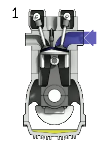
The function of a camshaft is dependent on how a valve works and the function of the cam itself.
ROCKER ARM : Rocker Arms are typically in between the pushrod and the intake and exhaust valves. They allow the pushrods to push up on the rocker arms and therefore push down on the valves. However, in Over head Cam applications the Cam will ride directly on the Rocker Arm.
In addition to just changing the the direction of the motion from up on the rocker arm to down on the valve, the Rocker Arm changes the amount of motion transferred. Typically a Rocker Arm will "multiply" its motion by a Rocker Arm Ratio by a factor of 1.45 to 1.7, meaning that for each .100" of pushrod motion you would get .145" to .170" of valve motion.
In this project, we will model all the parts of an IC Engine train valve and then assemble them in SolidWorks. The motion analysis is going to be carried out for the following conditions :
| Sl.No | CAM Lift (mm) | Speed (RPM) | Material |
| 1 | 3.5 | 1500 | Cast Carbon Steel |
| 2 | 6 | 1500 |
Cast Carbon Steel |
Following parameters are also obtained :
Valve Lift.
The contact force between
Cam and Push Rod
Pushrod and Rocker Arm
Rocker Arm and Valve
PROCEDURE :
- Create 3D drawings of the cam, push rod(cam follower), rocker arm, valve and valve stem by providing the correct parameter values.
cam
push rod
rocker arm
valve stem
valve
- The final assembly after applying the proper mates between different components is obtained as
- Now we will perform motion analysis on the assembly for the 2 cases.
Case 1 : Cam lift = 3.5 mm ; Speed = 1500 rpm ; Material = cast carbon steel.
By using the formula of cam lift,
L= 11 mm
1. Linear displacement of valve.
2. Contact force between cam and push rod.
3. Contact force between push rod and rocker arm.
4. Contact force between rockerarm and valve.
5. Contact force variation of rocker arm and valve wrt x-direction.
Case 2 :
Cam lift = 6 mm ; Speed = 1500 rpm ; Material = cast carbon steel.
By using the formula of cam lift,
L= 13.5 mm
1. Linear displacement of valve.
2. Contact force between cam and push rod.
3. Contact force between push rod and rocker arm.
4.Contact force between rockerarm and valve.
5. Contact force variation of rocker arm and valve wrt x-direction.
Q. Why the contact force between the Rocker arm and valve varies while measuring with respect to the X direction and measuring with respect to magnitude?
The magnitude represents the net force between the parts while the contact force along the x-dir represents the frictional force that arises due to the sliding of rocker arm over valve head.
The change in the direction of force is because the rocker arm first slides towards the origin giving a positive friction force and then slides away from the origin giving a negative fricction force, hence making the plots appear opposite to each other.