MBD Simulation on a Piston Assembly
Aim : To model and assemble the parts of the piston to perform motion analysis on various conditions
Objective :
1) To perform motion analysis for the following conditions of wrist pin position,
- Condition 1: 0 mm offset and clockwise rotation of the crank
- Condition 2: 10mm Positive offset and clockwise rotation of the crank
- Case 3: 10 mm Negative offset and clockwise rotation of the crank
2) Plotting the linear displacement of the piston head for the above-mentioned conditions and superimposing them for better comparison
Introduction :
Motion analysis helps the user to get the actual simulation of the product under observation. It is usually performed on the systems which are complicated. Motion analysis provides various information of the moving components such as velocity, acceleration, reactive forces acting on it, etc. It also plays a significant role in determining the movement and checking the constraints acting on the moving components. The data obtained from the study could be further used for development of the product.
The present report shows the motion analysis performed on a piston assembly. Piston is a key component of various machines like reciprocating pumps, reciprocating engines, pneumatic cylinders, hydraulic cylinders, etc. It is very important in engine as its sole purpose is to transfer the force developed during the power stroke to the crankshaft through connecting rod in order to propel the vehicle. So, it becomes necessary that it must transfer maximum power at optimal conditions and hence motion analysis of the same could help us for better development. The piston assembly consists of Piston, Connecting Rod, Crank, End cap and Gudgeon pin.
Procedure :
- The cad models of the assembly are created as per the prescribed dimensions These are shown below :
- Piston :
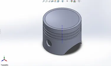
2. Connecting Rod :
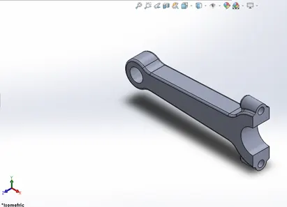
3. Crank :
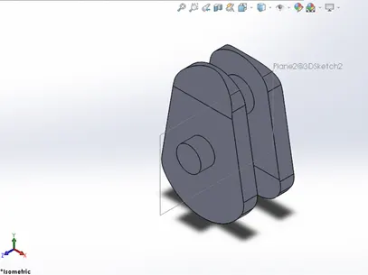
4. End Cap :
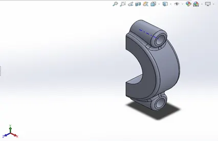
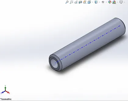
5. Gudgeon Pin :
- The models are then assembled by giving required constraints and mates as per the given conditions. This completes the assembly.
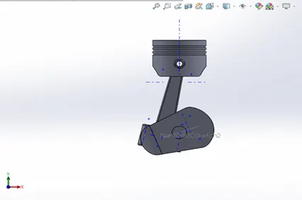
- Condition 1: 0 mm offset and clockwise rotation of the crank
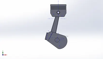
2. Condition 2: 10mm Positive offset and clockwise rotation of the crank
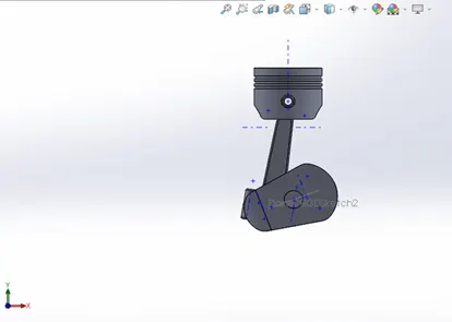
3. Condition 3: 10 mm Negative offset and clockwise rotation of the crank
- Next, motion analysis is to be performed. For this, we need to develop Contacts between the parts, provide gravity, adjust the frames, and give a speed of 2000 RPM to the crank.
- Once the required parameters are given as input, Run the motion analysis.
- After this, we can plot the required graphs.
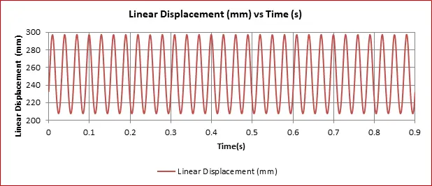
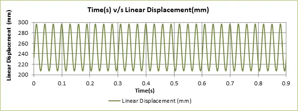
Results : The plot of linear displacement of piston head v/s time is obtained.
- Condition 1 : 0 mm offset and clockwise rotation of the crank
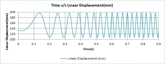
- Condition 2: 10mm Positive offset and clockwise rotation of the crank
- Condition 3: 10 mm Negative offset and clockwise rotation of the crank
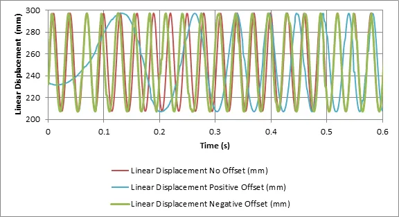
- Super-imposed plots :
Inference:
- From the superimposed graphs, it can be seen that the maximum distance traveled by all three pistons at different conditions is approximately the same.
- The motion of piston when provided with positive Offset (blue) takes some time to get the momentum as compared to other two cases.
- From the plot it can be concluded that when no is offset provided the response time is highest.
Video Animation :