MBD Simulation on a Piston Assembly
AIM:
To create different part of piston assembly and assemble them and run motion analysis for different position and plot linear displacement of piston head. The condition are as follows
| Sl.No |
Wrist Pin Offset ` |
Crank Speed (Rpm) |
| 1 | "0" mm | 2000 |
| 2 | 10 mm Positive | 2000 |
| 3 | 10 mm Negative | 2000 |
PISTON ASSEMBLY:
The piston assembly is an assembly that consist of piston head, end cap, connecting rod , wrist pin, crank. Here every part are assembled with neccessary constrains to achive the motion. Here the pistion from TDC comes to BDC what is called suction stroke where air is drawn in and again piston move to TDC where air is compressed and fuel is injected and fuels combust due to high temperature and pressure and now working stroke takes place where piston is returned to BDC and again piston move to TDC where exhaust stroke happens
PROCEDURE:
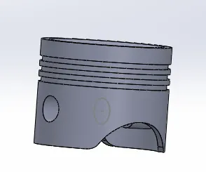
1. first part of the procedure to design pistion head . It is important component of piston assembly and reason why gas cycle happens
The dimensions are as follows
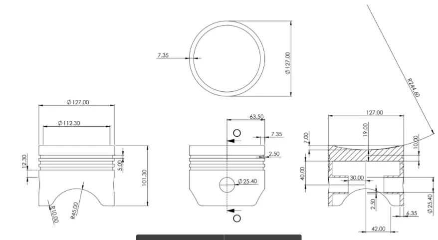
The final model is as follows
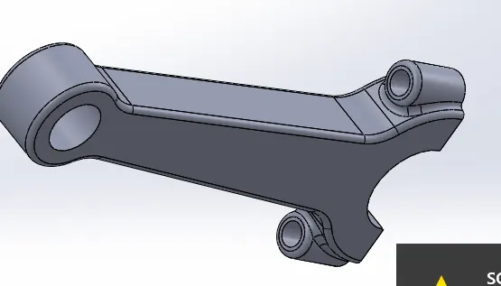
2. The second part is conneting rod it consist of 2 ends bigger end is connected to crank and smaller end is connected to piston wrist pin. It helps to translate piston head from TDC to BDC and it has both translatory and rotatory motion
The dimension of Connecting rod as follows
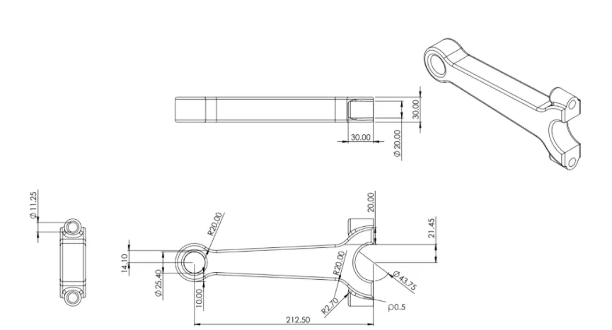
The model is follows
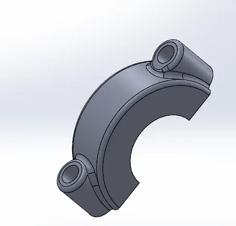
3. The third one is the end cap its helps to grip connecting rod to wrist pin inturn grip it to piston head
the dimension is as follows
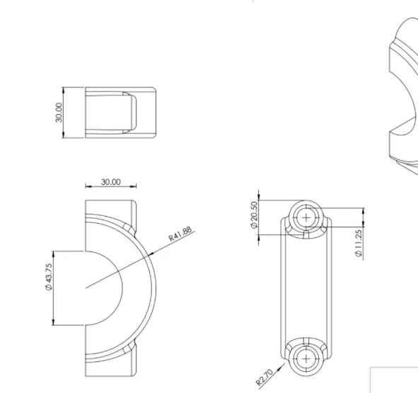
The model is as follows
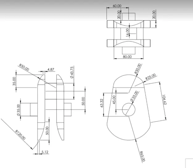
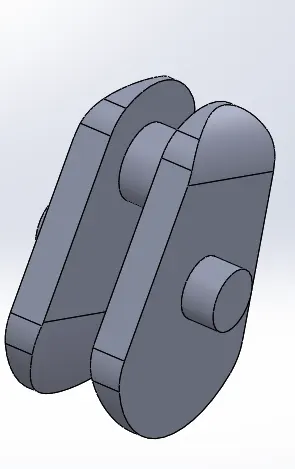
4. The main part is crank which has rotational motion to which main shaft , connecting rod and fly wheel are connected . It transmits power from piston head to gear system
The dimension is as follows
The modeled figure is as follows
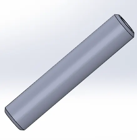
5. The wristpin connects connecting rod to piston head
The dimension is follows
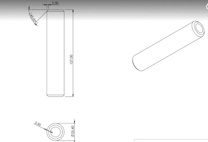
The model is follows
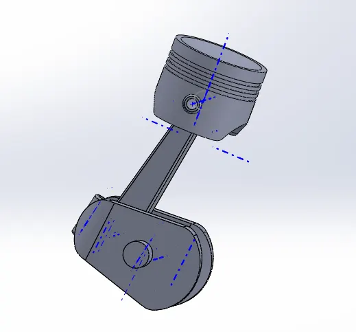
6. Now after apply several constrains and mates all the parts are assembled and final assembly is as follows
RESULT:
Condition 1:
| "0" mm wrist pin displacement | speed 2000 rmp |
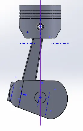
The model position is shown above here piston head axis is coincident with crank axis and the linear displacement graph is as follows
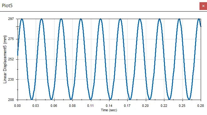
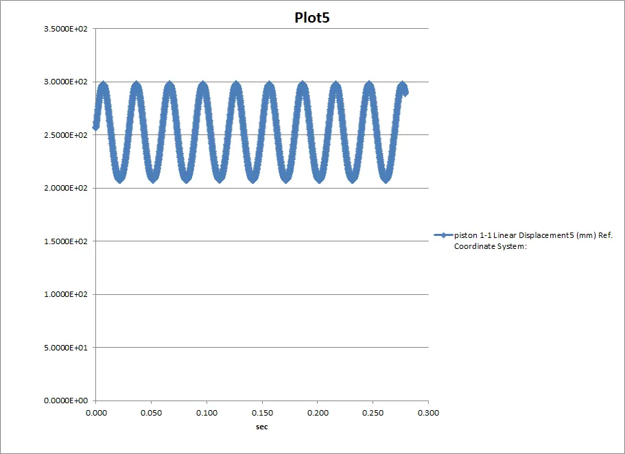
| piston 1-1 | ||
| Linear Displacement5 (mm) | ||
| Frame | Time | Ref. Coordinate System: |
| 1 | 0.000 | 2.5660E+02 |
| 2 | 0.000 | 2.5693E+02 |
| 3 | 0.000 | 2.5780E+02 |
| 4 | 0.000 | 2.5901E+02 |
| 5 | 0.000 | 2.6021E+02 |
| 6 | 0.001 | 2.6141E+02 |
| 7 | 0.001 | 2.6260E+02 |
| 8 | 0.001 | 2.6260E+02 |
| 9 | 0.001 | 2.6380E+02 |
| 10 | 0.001 | 2.6498E+02 |
| 11 | 0.001 | 2.6616E+02 |
| 12 | 0.001 | 2.6733E+02 |
| 13 | 0.001 | 2.6849E+02 |
| 14 | 0.001 | 2.6965E+02 |
| 15 | 0.002 | 2.7079E+02 |
| 16 | 0.002 | 2.7192E+02 |
| 17 | 0.002 | 2.7304E+02 |
| 18 | 0.002 | 2.7414E+02 |
| 19 | 0.002 | 2.7523E+02 |
| 20 | 0.002 | 2.7630E+02 |
| 21 | 0.002 | 2.7736E+02 |
| 22 | 0.002 | 2.7840E+02 |
| 23 | 0.003 | 2.7942E+02 |
| 24 | 0.003 | 2.8042E+02 |
| 25 | 0.003 | 2.8141E+02 |
| 26 | 0.003 | 2.8237E+02 |
| 27 | 0.003 | 2.8330E+02 |
| 28 | 0.003 | 2.8422E+02 |
| 29 | 0.003 | 2.8511E+02 |
| 30 | 0.003 | 2.8597E+02 |
| 31 | 0.004 | 2.8681E+02 |
| 32 | 0.004 | 2.8763E+02 |
| 33 | 0.004 | 2.8841E+02 |
| 34 | 0.004 | 2.8917E+02 |
| 35 | 0.004 | 2.8990E+02 |
| 36 | 0.004 | 2.9060E+02 |
| 37 | 0.004 | 2.9126E+02 |
| 38 | 0.004 | 2.9190E+02 |
| 39 | 0.005 | 2.9251E+02 |
| 40 | 0.005 | 2.9308E+02 |
| 41 | 0.005 | 2.9362E+02 |
| 42 | 0.005 | 2.9413E+02 |
| 43 | 0.005 | 2.9460E+02 |
| 44 | 0.005 | 2.9504E+02 |
| 45 | 0.005 | 2.9544E+02 |
| 46 | 0.005 | 2.9581E+02 |
| 47 | 0.006 | 2.9615E+02 |
| 48 | 0.006 | 2.9644E+02 |
| 49 | 0.006 | 2.9670E+02 |
| 50 | 0.006 | 2.9670E+02 |
| 51 | 0.006 | 2.9693E+02 |
| 52 | 0.006 | 2.9693E+02 |
| 53 | 0.006 | 2.9712E+02 |
| 54 | 0.006 | 2.9712E+02 |
| 55 | 0.006 | 2.9727E+02 |
| 56 | 0.006 | 2.9727E+02 |
| 57 | 0.006 | 2.9738E+02 |
| 58 | 0.006 | 2.9738E+02 |
| 59 | 0.006 | 2.9746E+02 |
| 60 | 0.006 | 2.9746E+02 |
| 61 | 0.007 | 2.9749E+02 |
| 62 | 0.007 | 2.9749E+02 |
| 63 | 0.007 | 2.9750E+02 |
| 64 | 0.007 | 2.9746E+02 |
| 65 | 0.007 | 2.9739E+02 |
| 66 | 0.007 | 2.9728E+02 |
| 67 | 0.007 | 2.9728E+02 |
| 68 | 0.007 | 2.9713E+02 |
| 69 | 0.007 | 2.9713E+02 |
| 70 | 0.007 | 2.9694E+02 |
POSITION 2:
| "-10" mm wrist pin displacement | speed 2000 rmp |
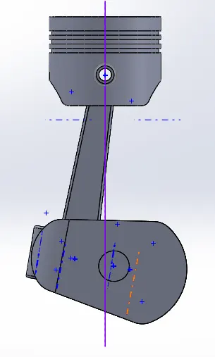
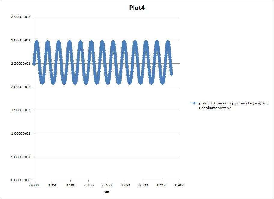
The negative 10 mm displacement is as above and the result is as follows
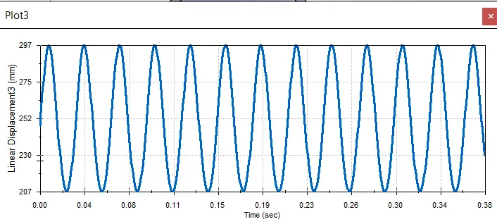
| piston 1-1 | ||
| Linear Displacement4 (mm) | ||
| Frame | Time | Ref. Coordinate System: |
| 1 | 0.000 | 2.4791E+02 |
| 2 | 0.000 | 2.4865E+02 |
| 3 | 0.000 | 2.4910E+02 |
| 4 | 0.000 | 2.5031E+02 |
| 5 | 0.000 | 2.5151E+02 |
| 6 | 0.001 | 2.5273E+02 |
| 7 | 0.001 | 2.5394E+02 |
| 8 | 0.001 | 2.5516E+02 |
| 9 | 0.001 | 2.5637E+02 |
| 10 | 0.001 | 2.5759E+02 |
| 11 | 0.001 | 2.5881E+02 |
| 12 | 0.001 | 2.6002E+02 |
| 13 | 0.001 | 2.6123E+02 |
| 14 | 0.002 | 2.6244E+02 |
| 15 | 0.002 | 2.6364E+02 |
| 16 | 0.002 | 2.6484E+02 |
| 17 | 0.002 | 2.6603E+02 |
| 18 | 0.002 | 2.6721E+02 |
| 19 | 0.002 | 2.6839E+02 |
| 20 | 0.002 | 2.6955E+02 |
| 21 | 0.002 | 2.7070E+02 |
| 22 | 0.003 | 2.7184E+02 |
| 23 | 0.003 | 2.7296E+02 |
| 24 | 0.003 | 2.7408E+02 |
| 25 | 0.003 | 2.7517E+02 |
| 26 | 0.003 | 2.7625E+02 |
| 27 | 0.003 | 2.7732E+02 |
| 28 | 0.003 | 2.7836E+02 |
| 29 | 0.003 | 2.7939E+02 |
| 30 | 0.004 | 2.8039E+02 |
| 31 | 0.004 | 2.8138E+02 |
| 32 | 0.004 | 2.8234E+02 |
| 33 | 0.004 | 2.8328E+02 |
| 34 | 0.004 | 2.8420E+02 |
| 35 | 0.004 | 2.8509E+02 |
| 36 | 0.004 | 2.8595E+02 |
| 37 | 0.004 | 2.8679E+02 |
| 38 | 0.005 | 2.8760E+02 |
| 39 | 0.005 | 2.8839E+02 |
| 40 | 0.005 | 2.8914E+02 |
| 41 | 0.005 | 2.8987E+02 |
| 42 | 0.005 | 2.9056E+02 |
| 43 | 0.005 | 2.9123E+02 |
| 44 | 0.005 | 2.9186E+02 |
3. CONDITION 3:
| "10" mm wrist pin displacement | speed 2000 rmp |
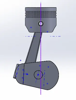
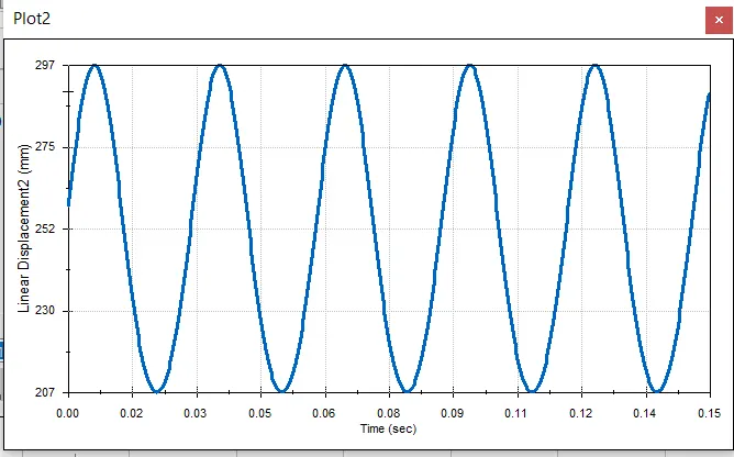
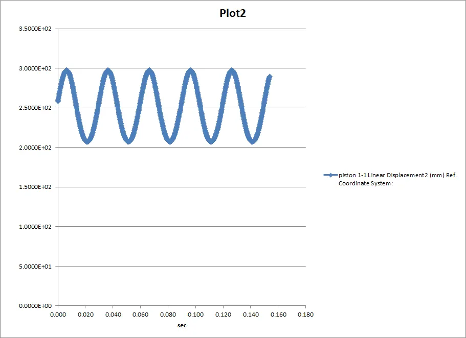
The postive 10mm displacement is as above and result is as follows
| piston 1-1 | ||
| Linear Displacement2 (mm) | ||
| Frame | Time | Ref. Coordinate System: |
| 1 | 0.000 | 2.5831E+02 |
| 2 | 0.000 | 2.5905E+02 |
| 3 | 0.000 | 2.5950E+02 |
| 4 | 0.000 | 2.6069E+02 |
| 5 | 0.000 | 2.6188E+02 |
| 6 | 0.001 | 2.6306E+02 |
| 7 | 0.001 | 2.6424E+02 |
| 8 | 0.001 | 2.6541E+02 |
| 9 | 0.001 | 2.6658E+02 |
| 10 | 0.001 | 2.6774E+02 |
| 11 | 0.001 | 2.6889E+02 |
| 12 | 0.001 | 2.7002E+02 |
| 13 | 0.001 | 2.7115E+02 |
| 14 | 0.002 | 2.7227E+02 |
| 15 | 0.002 | 2.7337E+02 |
| 16 | 0.002 | 2.7446E+02 |
| 17 | 0.002 | 2.7554E+02 |
| 18 | 0.002 | 2.7660E+02 |
| 19 | 0.002 | 2.7764E+02 |
| 20 | 0.002 | 2.7866E+02 |
| 21 | 0.002 | 2.7967E+02 |
| 22 | 0.003 | 2.8066E+02 |
| 23 | 0.003 | 2.8163E+02 |
| 24 | 0.003 | 2.8257E+02 |
| 25 | 0.003 | 2.8349E+02 |
| 26 | 0.003 | 2.8439E+02 |
| 27 | 0.003 | 2.8527E+02 |
| 28 | 0.003 | 2.8612E+02 |
| 29 | 0.003 | 2.8695E+02 |
| 30 | 0.004 | 2.8774E+02 |
| 31 | 0.004 | 2.8852E+02 |
| 32 | 0.004 | 2.8926E+02 |
| 33 | 0.004 | 2.8997E+02 |
| 34 | 0.004 | 2.9066E+02 |
| 35 | 0.004 | 2.9131E+02 |
| 36 | 0.004 | 2.9194E+02 |
| 37 | 0.004 | 2.9253E+02 |
| 38 | 0.005 | 2.9309E+02 |
| 39 | 0.005 | 2.9361E+02 |
| 40 | 0.005 | 2.9411E+02 |
From the above images you can note the piston head surface has different starting point and ending point in a cycle for negative displacement of wrist pin the displacement starts below average but for the positive displacement the starting point is above average ie delayed start whereas the 0 displacement of wristpin is considered as average starting point