MBD Simulation on a Piston Assembly
Abstract
In this project, the main objective is to model a piston and its associated parts i.e. piston head, wrist pin, connecting rod, end cap, and crank then run an MBD simulation on that. Motion analysis is done at 1200rpm and frame rate 7200fps with precision contact for three different parameters then plots of the linear displacement of the piston is considered.
1. Introduction
Piston motion analysis:
Piston motion analysis is the study of the reciprocating motion of the piston in the cylinder and the motion of the assembly attached i.e. connecting rod, end cap, crankshaft & wrist pin. First of all for the assembly of a connecting rod, crankshaft, end cap, wrist pin and piston itself, we will prepare the geometric model of all the necessary components.
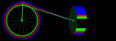
Fig 1. Show the piston motion at various crank radius.
We have to design all the different parts of the cylinder piston arrangement separately. The parts are as follows :
- Piston Head
- Gudgeon Pin (Wrist pin)
- Connecting rod
- End Cap
- Crank
After designing all the parts we have to complete the assembly.
This project aims to analyze the motion analysis of the piston and the parameters set to achieve the plots of linear displacement are given below:
2. Geometry of the parts
- Piston Head: piston is a component of reciprocating engines, reciprocating pumps, gas compressors and pneumatic cylinders, among other similar mechanisms. It is the moving component that is contained by a cylinder and is made gas-tight by piston rings. In an engine, its purpose is to transfer force from expanding gas in the cylinder to the crankshaft via a piston rod and/or connecting rod.
- Gudgeon Pin (Wrist pin): Drawing a circle and then using extrude option and then giving chamfer to each end.
- Connecting rod: Drawing two sets of two concentric circles at some distance and then joining them with a line than giving fillet to it then use the extrude option and use extrude cut to remove unwanted part of connecting rod then using extrude and extrude cut we will prepare the bolting area.
- End Cap: End cap is connected to the end of the connecting rod, which is assembled crank.
- Crank: Is a mechanical part able to convert the reciprocating motion from the piston into rotational motion.
- Final assembly: The piston, connecting rod, wrist pin, end cap and the crank are assembled as shown below using assembly mate option. First, the crank is made coincident with the assembly planes so that it can rotate about its axis and then connecting rod and end cap assembly is made coincident with the crank axis. The wrist pin is made coincident with the piston and with its front plane and it is then assembled to the connecting rod. This will result in the required assembly for the motion analysis.
3. Motion Study Analysis
The motion study: In the Motion study the following steps are performed.
- Select motion analysis in the drop-down menu.
- Motor is given to crank with the speed 2000 RPM.
- Frames per second are given as 12000 with precise contact.
- Contact is given between endpin and crank, crank and connecting rod, connecting rod and wrist pin and wrist pin and piston. The material selected for each case is steel (Dry).
- Gravity in the Y direction.
Calculation is performed for the motion analysis for about 3 sec. Linear displacement of the piston head w.r.t time is obtained.
As there are three parameters,
Case 1: Motion Analysis for "0" mm Offset
- Motion analysis is performed on this and linear displacement plot is obtained
Case 2: Motion Analysis for 10 mm positive Offset
- Motion analysis is performed on this and linear displacement plot is obtained
Case 3: Motion Analysis for 10 mm Negative Offset
- Motion analysis is performed on this and linear displacement plot is obtained
Superimposed graph: Here linear displacement graph from each case is exported to excel and then superimposed there.
4.Observation and conclusion:
From the plots obtained, we can see that Linear Displacement increases as we move from negative wrist pin offset to positive wrist pin offset i.e. the magnitude of the Linear displacement increases.
Also from the graph obtained after superimposing it we can see that for a given time frequency of rotation of piston with wrist pin offset negative is higher comparatively to one with zero offset and pin with zero offset has higher frequency than one with a positive offset.
https://drive.google.com/file/d/12GS4BwTAg3CzI9YuAczsCvPeTwtu0q3t/view?usp=drivesdk