Exploring the Role of Offset in IC Engine Efficiency through Multibody Dynamic Simulation of a Piston Assembly
Aim: Modelling IC Engine Piston Assembly in SOLIDWORKS and performing a motion study with effects on following design considerations:
- 0mm offset (between wrist pin and the axis of the crank)
- 10 mm positive offset (between wrist pin and the axis of the crank)
- 10 mm negative offset (between wrist pin and the axis of the crank)
Theory:
An Internal Combustion engine (IC engine) is an engine in which the combustion of fuel, such as petrol or diesel, takes place inside the engine cylinder. In petrol engine, air and petrol is mixed in correct proportion in the carburetter and then passed into the cylinder. This mixture is ignited by means of a spark produced by the spark plug. Since the ignition is done by spark, the petrol engine is called Spark Ignition engine (SI Engine). In the diesel engine, the air entrapped in the cylinder during the suction stroke is highly compressed during compression stroke. This compression increases the air temperature beyond the self-ignition temperature of diesel. The desired quantity of diesel in the form of fine spray is then admitted into the cylinder near the end of the compression stroke. The turbulent hot air ignites the diesel. Since the ignition is done by compression of air, the diesel engine is called Compression Ignition engine (CI engine).Below two figures show the working of SI and CI engines respectively.
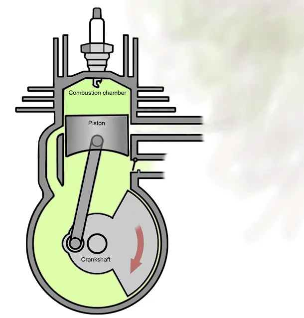
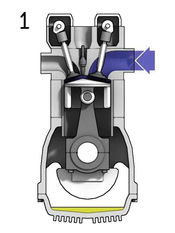
Although Internal Combustion Engine consists of a large number of parts, only important components were modelled in this study which are as follows:
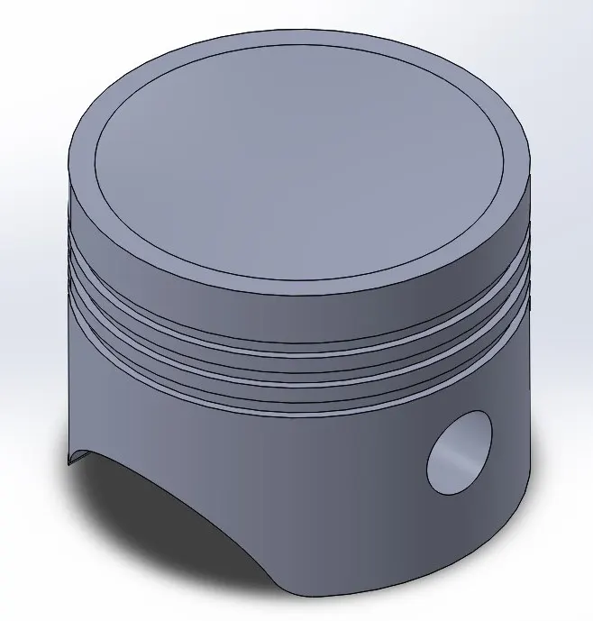
- Piston head
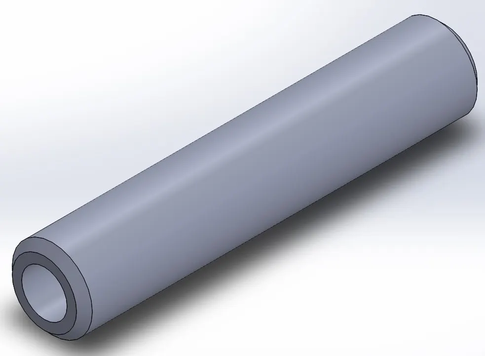
- Wrist or gudgeon pin
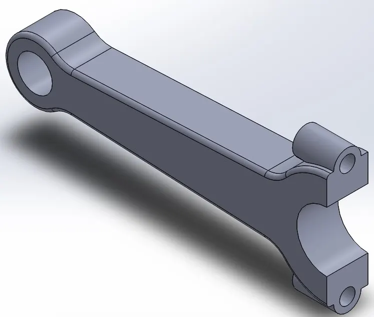
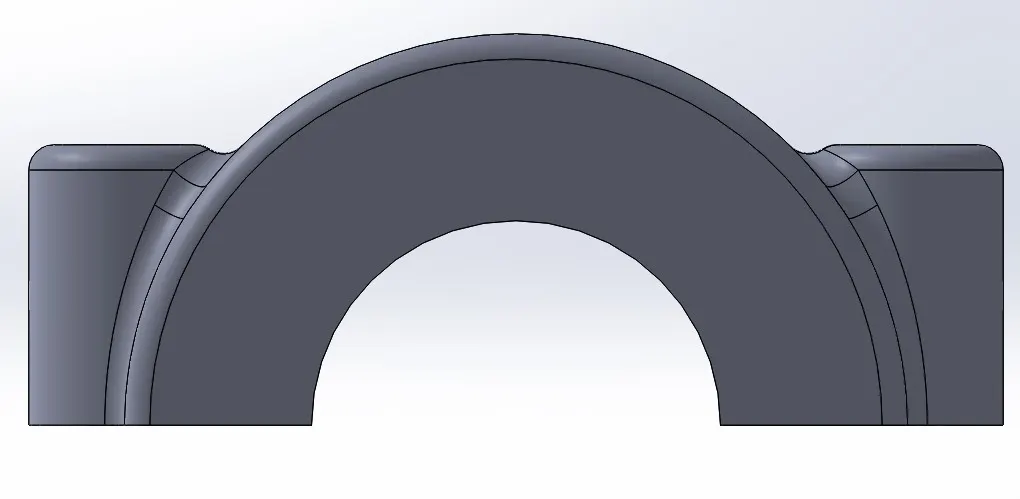
- Connecting rod with big and small ends
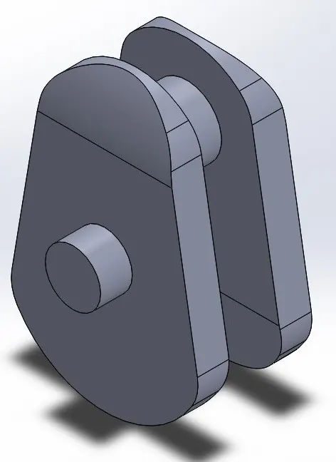
- Crank
Modeling parts in Solid Works
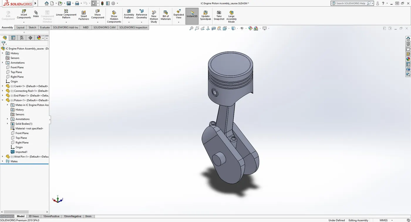
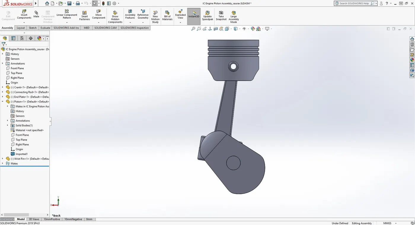
All the above-mentioned parts were modelled in solid works along with their assembly which are shown below:
Piston Head and Wrist or gudgen Pin
Connecting rod and Crank
Connecting rod with both caps
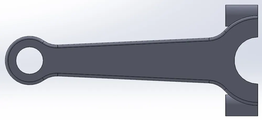
Assembly
Creating Motion Study:
Steps followed in the motion study are summarised as follows:
- Started with running Solid Works Motion Add-in and creating a motion study.
- Setting up a motor at the axis of the crank giving them conditions of constant speed with 2000 rpm (CW).
- Creating Solid body contacts with specified material as Steel(Dry).
- Setting up gravity on Y direction
- Changing the Motion Study parameters to Precise Contacts with 12000 frames per second.
- As the set fps are so high, the study was done only for 0.2 seconds which were sufficient for the crank to rotate upto three complete revolutions.
Three different conditions were setup in which the axis of wrist pin and the axis of crank were varied which are shown as below:
CASE1 : With 0 mm Offset
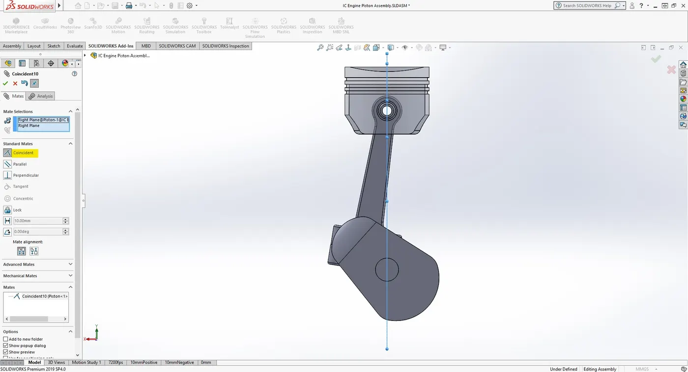
Above figure shows that the axis of the wrist pin and the axis of the crank are collinear with zero offset between them.
Angular velocity and Linear displacement of the Piston Head were plotted against time.
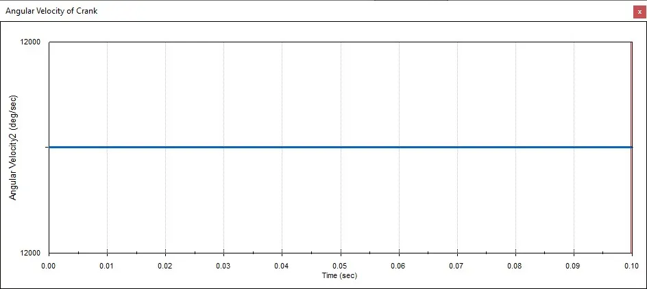
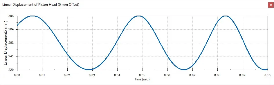
As we set the constant speed conditions, it is clear that the angular velocity at the crank remains constant along the time.
The linear displacement follows sine wave curve.
CASE 2 : With 10 mm Positive Offset
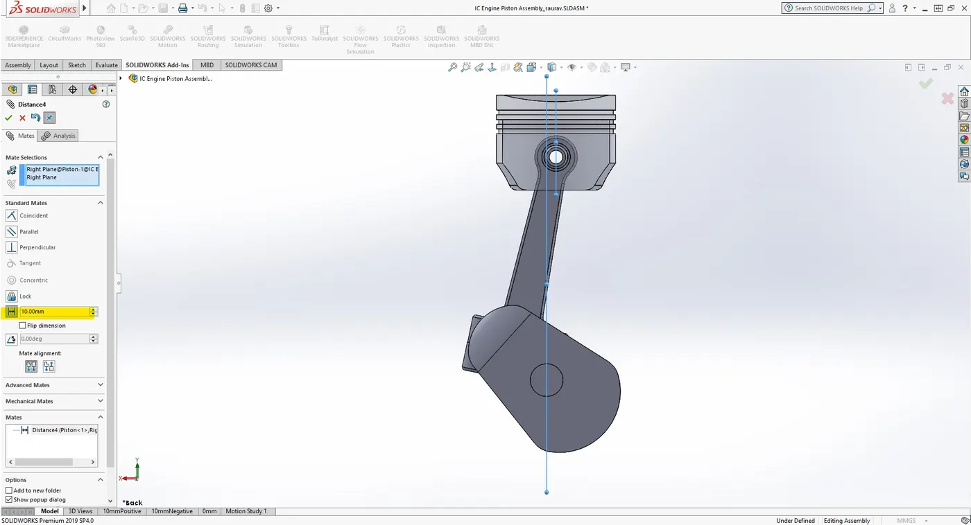
Above figure shows that the axis of the wrist pin and the axis of the crank are in 10 mm offset (in positive direction) between them.
Linear displacement of the Piston Head were again plotted against time.
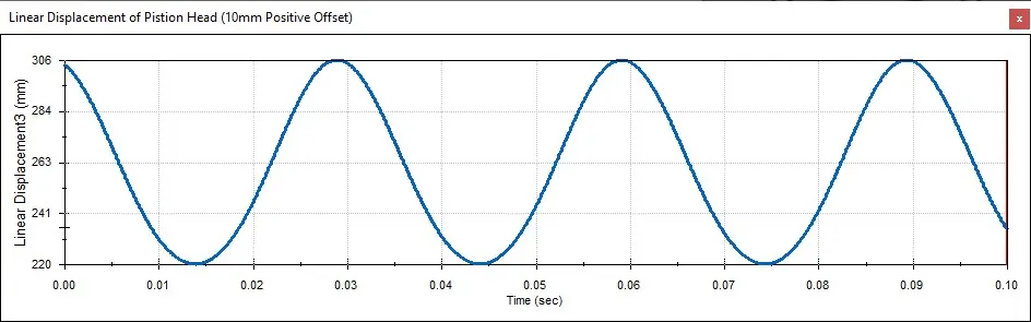
Although the graph seems similar to the previous case, when closely looked it can be seen that there is a lag in between them which could be seen when compared with each other.
CASE 3 : With 10 mm Negative Offset
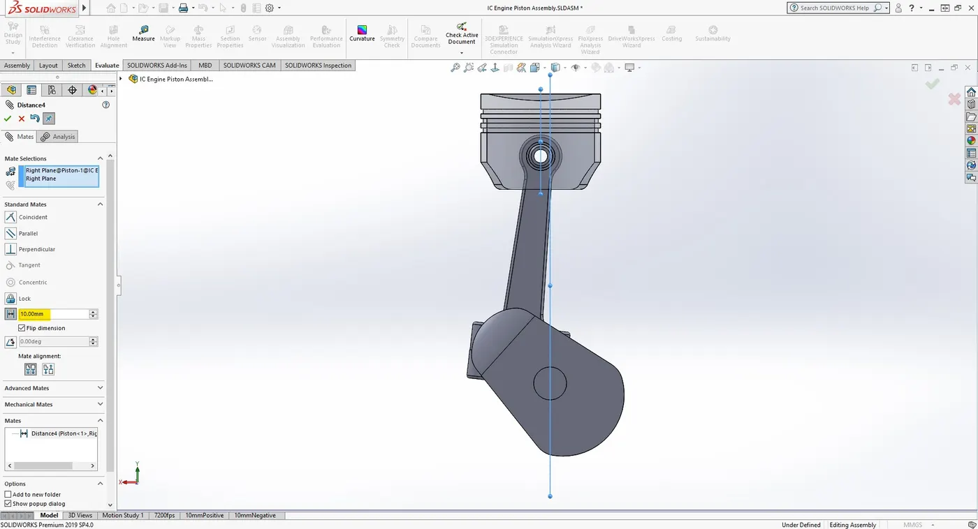
Above figure shows that the axis of the wrist pin and the axis of the crank are in 10 mm offset (in negative direction) between them.
Linear displacement of the Piston Head were again plotted against time.
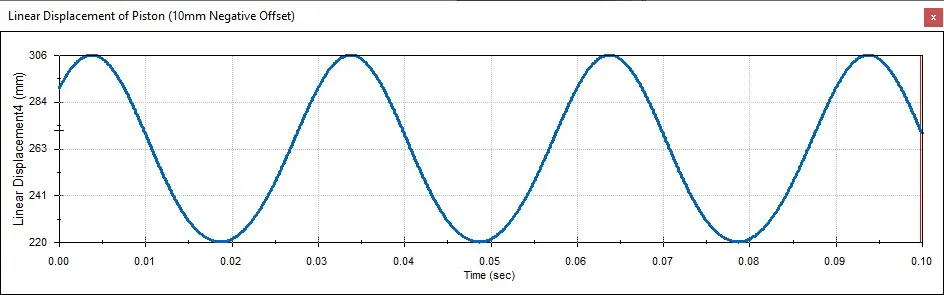
Although the graph seems similar to the previous case, when closely looked it can be seen that there is a lag in between them which could be seen when compared with each other.
Comparison of above cases
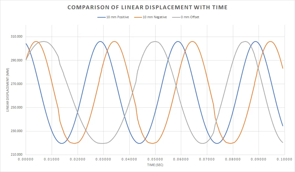
From the Above graph we can conclude the following key Points:
- Due to the offset, there is a delay in the displacement values.
- Offsetting is a very crucial while designing any IC Engine assembly which can improve the thermodynamic efficiency.
- It also suggests that the piston design is a critical factor to consider when attempting to improve friction with an offset crankshaft design.
Animation Video
The video just shows the animation with zero offet Condition.
Video URL: https://youtu.be/kEhiPluhZCw
References
- https://www.mechanicalbooster.com/2016/08/different-types-of-engine.html
- Machine Design book by V.B Bhandari