Introduction to REVIT concepts
Q1) From the file menu, create a new project (Structural / Architectural / Construction template ) and name the project appropriately?
ANS:
AIM: To create a new project from the file menu and need to name the project appropriately.
INTRODUCTION:
For creating a project, select a template from the Projects list or the New Project dialog box.
To configure the project, choose Manage Project Information and enter information in the Project Information dialog box.
Revit then updates the title block for every sheet.
PROCEDURE:
Step:1
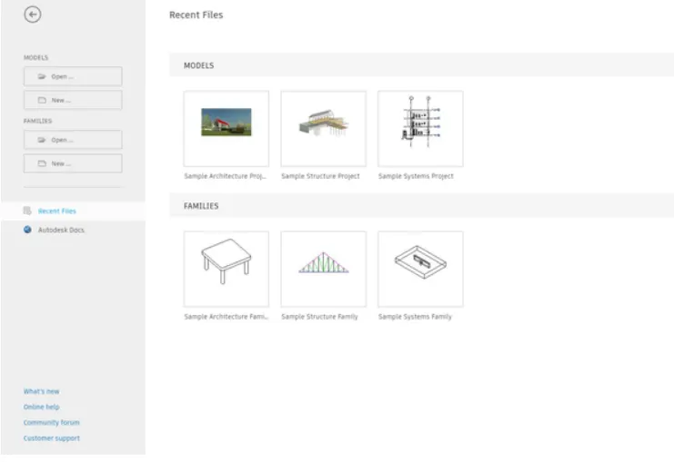
First open the Revit software as shown below.
Step: 2
Next select the file toolbar, the new tab is visible. Then select the new option.
From the new option select the project to create new project as shown below.
Step:-3
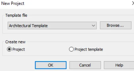
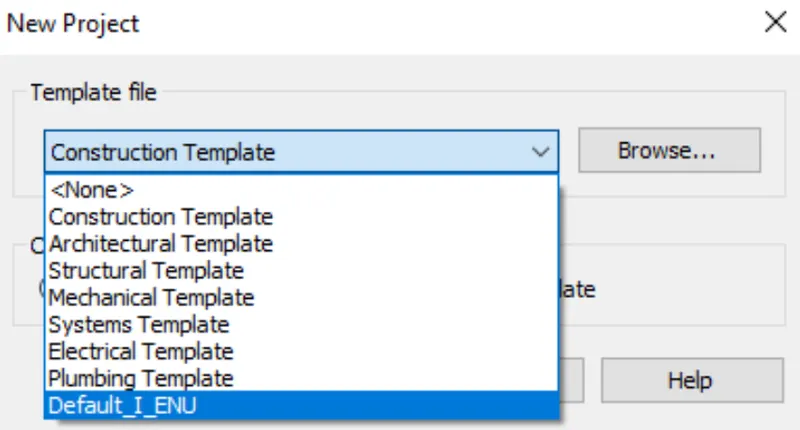
Next the template file tab will be wisible on the screen.
Select the construct template in the template file as shown below.
Step:-4
Next we need to name the project.
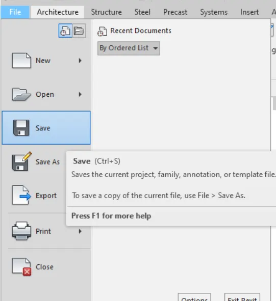
Open the file toolbar. click on the save as option, then the new tab will be visible.
Then name the project as projectl.rvt as shown below.
RESULT:
Created a new project from the file menu and saved the project with the name of project1.rvt.
Q2) Save the new project file. Close and open using icons from file toolbar?
ANS:
AIM: To save the new project file and need to close and open using icons from file toolbar.
INTRODUCTION:
For creating a project, select a template from the Projects list or the New Project dialog box
To configure the project, choose Manage Project Information and enter information in the Project Information dialog box,
Revit then updates the title block for every sheet.
By opening the file the previous files tab will be open and then we need to select the any file from the previous created files. By clicking the close option the project will be be closed.
PROCEDURE
Step:-1
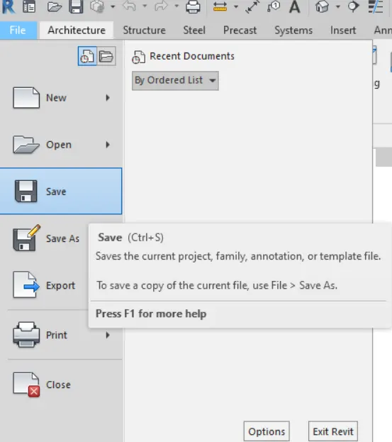
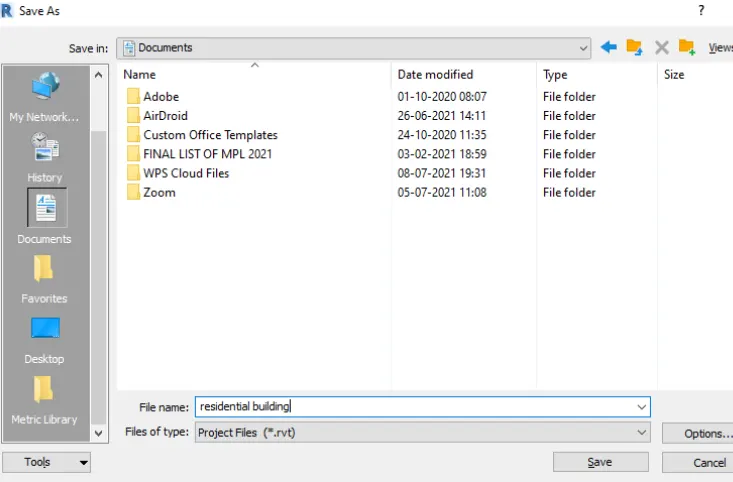
Open the file toolbar, click on the save option, then the new tab will be visible.
Step:-2
Then name the project as residential building as shown.
Step:-3
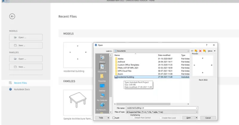
Open the file toolbar, click on the open option, then the new tab will be visible.
The previous files tab will be open and then we need to select the any file from the previous created files.
RESULT:
• The new project file has been saved and we opened and closed the new project using the icons from the toolbar.
Q3) From the architecture/ structure toolbar familiarize with options to draw a wall. Create a rectangular layout of walls of about 40’-0” X 35’-0”?
ANS:
AIM:- To draw a rectangular layout of walls of about 40'-0" X 35'-0" from the architecture/structure toolbar.
INTRODUCTION:
For creating a project, select a template from the Projects list or the New Project dialog box.
To configure the project, choose Manage Project Information and enter information in the Project Information dialog box.
Revit then updates the title block for every sheet.
There are different types of wall sizes and wall types in the architecture toolbar.
We can select different types of walls to the projects.
PROCEDURE:
Step:-1
open the revit file.
from previous saved archeticural building named file.
for architecural to be in impherical units.
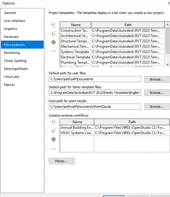
go to file menu-select option.
click on the file location.
STEP: 2
click on + symbol to add the template.
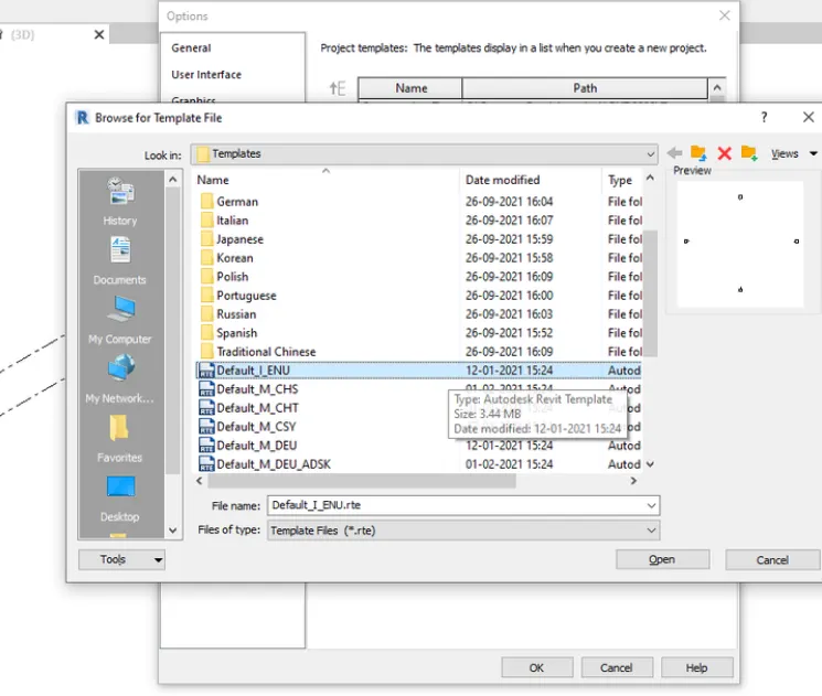
once it is clicked,computer file menu opens-select window c.
then RVT 2022-select template.
from template option displyed-select DEFAULT_I_ENG.
STEP: 3
again go back to file menu,select new and select default_i_eng.
STEP: 4
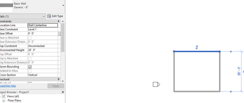
select architecural wall.
select basic concrete 8" width type wall.
select line command,enter first value as 40' towards right.
35' towards down and 40' towards right and connect the first point.
RESULT:
Q4) From the Annotate toolbar use the aligned option to add dimensions to the layout?
ANS:
AIM:- Use the aligned option to add dimensions to the layout from the annotate toolbar.
INTRODUCTION:
In this annotate tool bar aligned option is used to dimension the objects and any other 3D models or any other drawing
In this we used the annotate toolbar to dimension the rectangular layout using the aligned option in the annotate toolba
PROCEDURE:
Step:-1
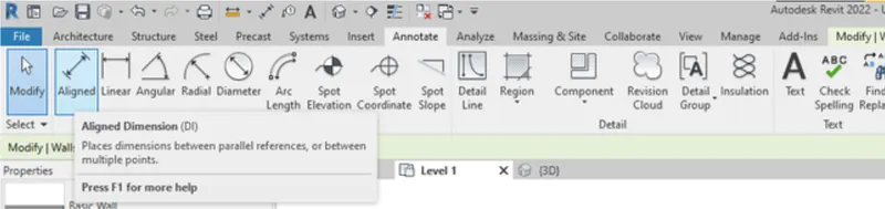
First we click on the annotate toolbar and select the aligned option to dimension the rectangular layour, as shown below.
STEP: 2
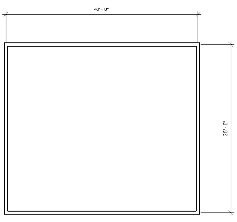
place cursor on one end of wall and click on another end of wall.
repeat the same for another side of the layout also.
Q5) Use the properties browser to switch to different wall types?
ANS:
AIM: To switch to the different wall types using the properties browser.
INTRODUCTION:
From the rectangular layout we can change wall type by selecting the particular wall.
In the properties browser there will be different wall sizes.
PROCEDURE:
Step:-1
We select the default 3D view option to view the rectangular layout to the 3D view, as shown below.
select one side wall from rectangular layout.
once u select,properties bar display type of wall.
click on properties and changle the wall to concrete 6" from family of walls.

RESULT:
Q6) Create a 3D view from the view toolbar and save the view with the appropriate name?
ANS:
AIM: To create a 3D view from the view toolbar and need to save the view with the appropriate name.
INTRODUCTION:
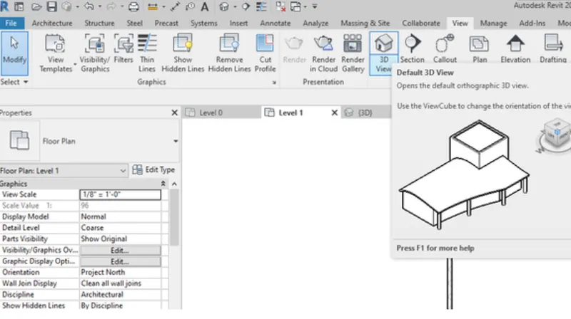
• In the view toolbar we can see different options, they are shown below.
- View template
- Visibility/graphics
- Filters
- Thin lines
- Show hidden lines
- Remove hidden lines
- Cut profile
- Render
- Render in cloud
- Render gallery
- 3D view
- Section
- Callout
- Plan views
- Elevation
- Drafting view
- Legends
- Schedules
- Scope box
PROCEDURE:
Step:-1
Select the view toolbar and select the 3D view option.
after drafting the layout.
click on view toolbar.
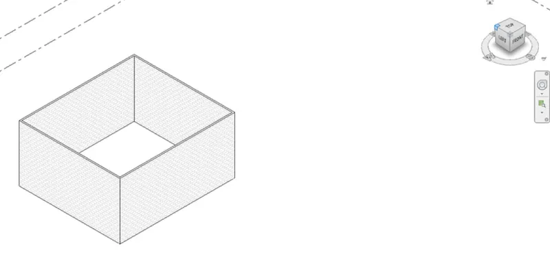
click on 3D view icon,display the 3d view of the layout.
once the view is set,rename the current view as 3d-wall.
RESULT:
Q7) Navigate through the 3D model using the view cube. Orbit/pan through the model layout created?
ANS:
AIM: - Use the view cube to navigate through the 3D model and orbit/pan through the model layout.
INTRODUCTION:
View cube is used to navigate the 3d model in any direction.
Orbit is also used to navigate the 3d model to any direction.
Pan is used to navigate the 3d model to the positions.
PROCEDURE:
Step:-1
First we move the curser to the view cube, then hold the view cube with the curser, then rotate the view in the different directions.
Step: 2
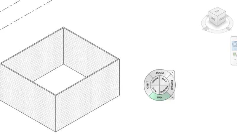
Use the view cube to rotate the 3D model by holding the view cube with the curser, as shown in the below figures.
Step: 3
. Open the steering wheel at right side of the screen, as shown below.
. After opening the steering wheel we need to select the pan option, then hold and move the 3d model view to the different positions as shown below.
RESULT:
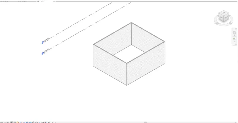
The three dimensional model is navigated using the view cube, Orbit and Pan by holding them with the curser, as shown in the above procedure.
Q8) Use the visibility settings option below to switch model to shaded, realistic, hidden lines options?
ANS:
AIM: - Use the visibility settings option to switch model to shaded, realistic, hidden lines options.
INTRODUCTION:
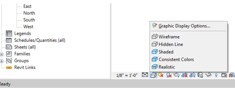
Using the visibility settings we can change the visibility of model, such as
- Wireframe
- Hidden line
- Shaded
- Consistent colours
- Realistic
- Ray trace
Here we need to change visibility of 3d model to three types, they are:
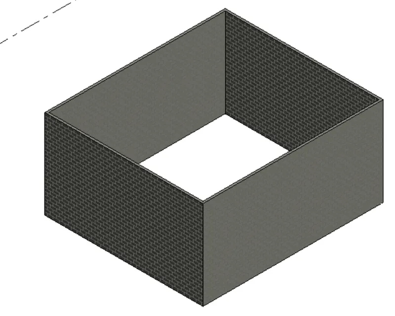
- Shaded
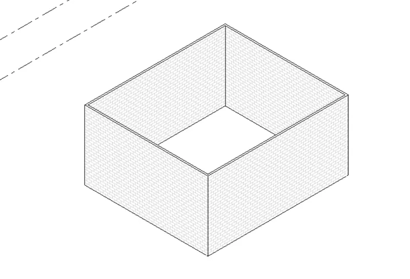
- Hidden line
- Realistic
PROCEDURE:
Step:-1
At the bottom click the graphic dispaly settings option, then select the Realistic option.
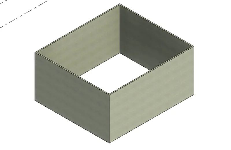
The visibility of the 3d model is changed to the realistic, as shown below.
RESULT:
REALISTIC VIEW
HIDDEN VIEW
SHADED VIEW:
Q9) Turn the sun path on and off to view shadings in the layout created?
ANS:
AIM:- To turn the sun path on and off to view shadings in the layout.
INTRODUCTION:
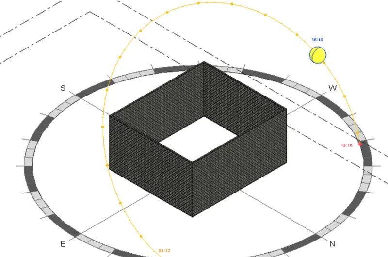
The sun's movement is an important consideration when designing high-performance buildings.
To understand the impact of the solar position on your building, you can use the Sun and Shadows settings in Revit to visualize them
position of the sun at your location at any time of the day or of the year.
You can also see the shadows that your project will be cast upon the surroundings as well as seeing the shadows cast upon your building surfaces.
PROCEDURE:
Step:-1
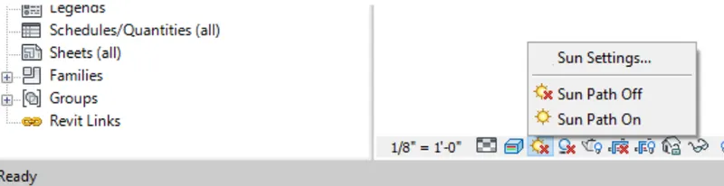
Click the Sun Path icon at the bottom of the Revit display area to open the Sun Path menu, select the sun path ON.
If a window pops up asking you to select the option Use the specified project location, date, and time instead to display the Sun Path select it.
Step:-2
Then the Sun Path Interface displays the ground compass, the position of the sun, time of day, and time of the year.
Step:-3
Click the Sun Path icon at the bottom of the Revit display area to open the Sun Path menu, select the sun path OFF
RESULT:
Q10) Use the Manage toolbar to enter project settings, project name, and project issue date (choose according to your convenience).?
ANS:
AIM:- Use the Manage toolbar to enter project settings, project name, and project issue date.
INTRODUCTION:
In the manage toolbar we can see different options, they are shown below.
- Materials
- Object Styles
- Snaps
- Project Information
- Project parameters
- Shared parameters
- Global parameters
- Transfer project standards
- Purge unused
- Project units
- Additional settings
- Design options
- Location
- Coordinates
- Position
- Structural settings
- MEP settings
- Manage links
- Manage images
- Phases
- Starting view
- Edit selection
- Decal types
- Select by ID
- Macro security
- Macro manager
- Dynamo
- Dynamo player
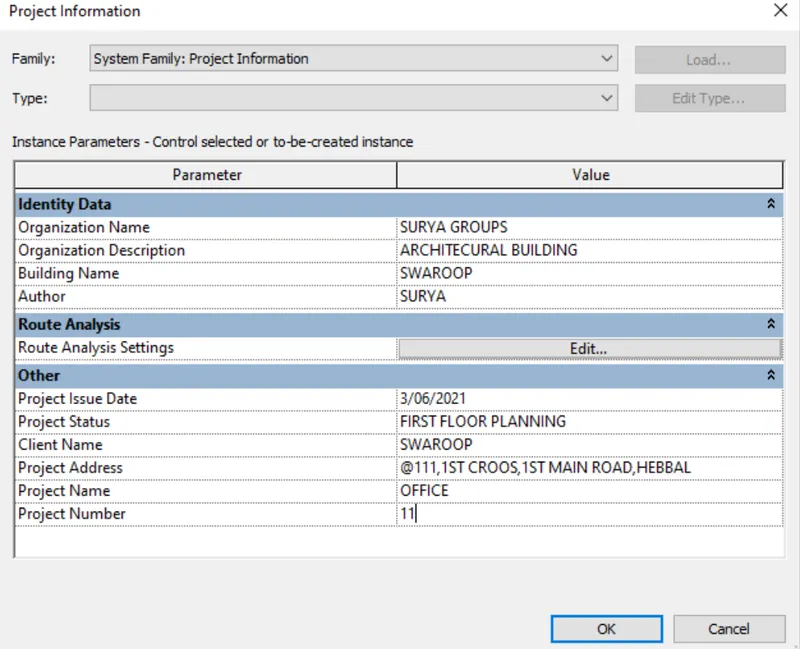
In this we need to select project information option and give the details of project.
PROCEDURE:
Step:-1
In the manage toolbar, we need to select the project information and enter the project details in the project settings.
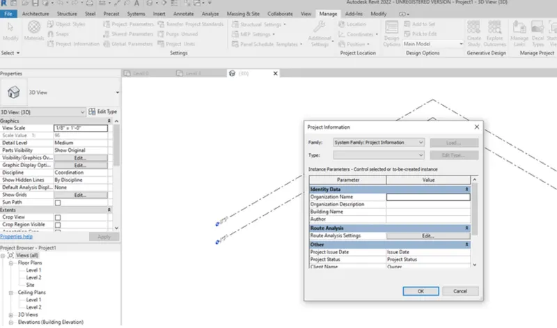
Step:-2
After selecting the project information option, the new tab will be visible on the screen as shown below.
RESULT:
Q11) What is the Analyze toolbar used in Revit? How it is beneficial for design and modeling?
ANS:
A) Analyze toolbar used in Revit and beneficial for design and modeling:

Analyse toolbar helps you to perform analysis on our structural building. The boundary conditions enable you to define point line and area boundary conditions in an analytical model. It will verify the boundary condition family types are loaded and assigned in your parametric features of the structural model, Similarly we can apply point load to a model to evaluate the performance of the building.
Similarly we can add and edit load cases to define the design standard suggested load case to a model we can combine different load cases using load combination icon, It will enable to add and edit load combinations for the analytical model. The main purpose of using the revit to evaluate the sustainability of the building that we modelling. So, we will be interested in evaluating the energy or energy optimization of the building that we are going to model. So, revit offers features such as, it creates an energy model fromthe features we have modelled in our projectand then the energy analytical model will be based on the conceptual masses. The building elements, and the material that we use to constr the building and the quantity and the amount of material that are used in our project.
Q12) What are the links that Revit supports to be linked to the model?
ANS: The links that Revit supports to be linked to the model are;
LINK REVIT:- This allows to link another revit model to the current model, Eg: we can link models together to specify the relative individual building on a campus or to coordinate efforts across disciplines (architectural, structural, mechanical)
LINK IFC:- To link IFC file to current model to reference its information for additional design work.
LINK CAD:- To link the 2d cad file to current revit file to create 3d by revit tools.
LINK TOPOGRAPHY: - to link current topography to the existing model. If the civil engineer has done topography detailing in other software such has civil 3D can be linked for rveit.

Q13) Why do you need the Collaborate tab in Revit? How it supports modeling and its efficiency?
ANS:

- The main disadvenatge in autocad is ,one person has to wait to start his set for modeling untill other person completes.
- This feature is used to help all set of group to work on a single model simultaneously.
- for example- if strcutural engineer needs the architect planning for column adjustment/vice versa,can link the ongoing model.
- It allows to edit and sync a model in local area or in wide area network.
- worksharing monitor helps us to review the information about acess to the file,editing request etc.,
- when collabration needs to be done with user of not same geography or area, it can be done using revit cloud work-sharing.
- when it comes to efficiemcy- will be more than autocad as the completion of each set of modeling will be done faster way and with minimal error.