Introduction to REVIT concepts
ASSIGNMENT NO 1
- From the file menu, create a new project ( structural / architectural / construction template ) and name the project appropriately.
Ans –
REVIT -
REVIT is an Autodesk product and is a building information modeling software for architects. Landscape architects, structural engineers, mechanical, electrical and plumbing engineers, Designers, and contractors. Using REVIT, we can create different templates respective to architectural drawings. Structural drawings and MEP drawings and can work simultaneously using collaboration tool.
PROCEDURE –
Open REVIT
Click the window button and type REVIT and press enter.
Once the REVIT is open, the home page is look like this.
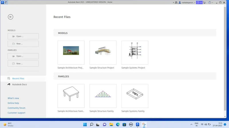
Creation of architectural template –
Click on new from the home page.
In the dialogue box click on the architectural template
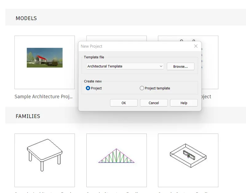
Click on create new project.
Click OK to open the architectural template.
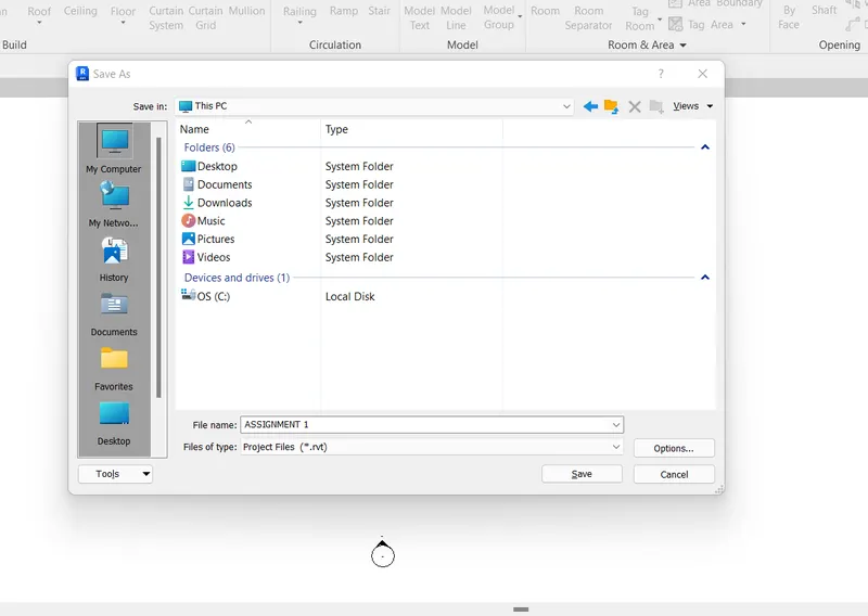
Click on the save button, dialogue box will appear and save the file name.
Name the file as ASSIGNMENT NO 1 and click on save.
Result –
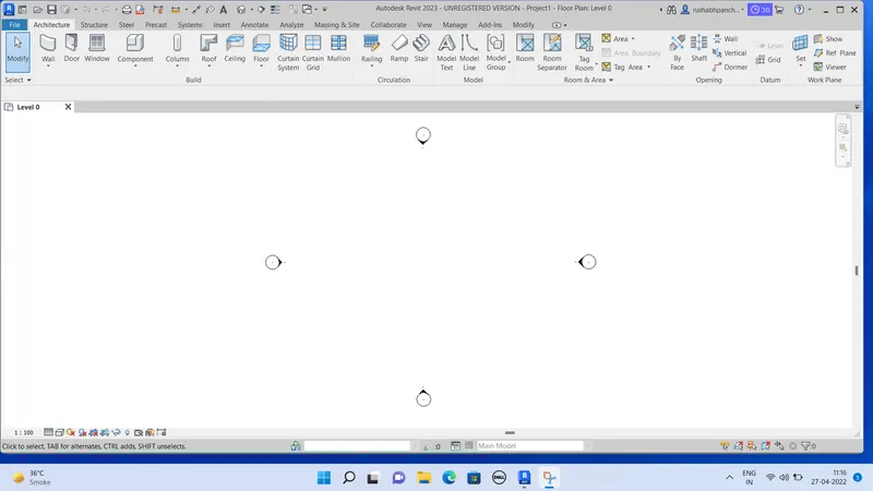
- Save the new project file. Close and open using icons from the file toolbar.
Ans –
REVIT -
REVIT is an Autodesk product and is a building information modeling software for architects. Landscape architects, structural engineers, mechanical, electrical and plumbing engineers, Designers, and contractors. Using REVIT, we can create different templates respective to architectural drawings. Structural drawings and MEP drawings. These files can be opened from the file tab in REVIT.
PROCEDURE –
Open REVIT.
Click the windows button and type REVIT and press enter.
Once the REVIT is open the home page is as follows.
Open any template drawing created.
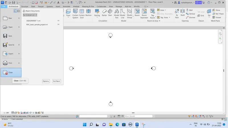
Click on file tab and click on new.
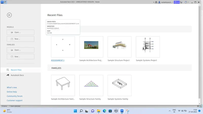
After clicking on new, a page will appear.
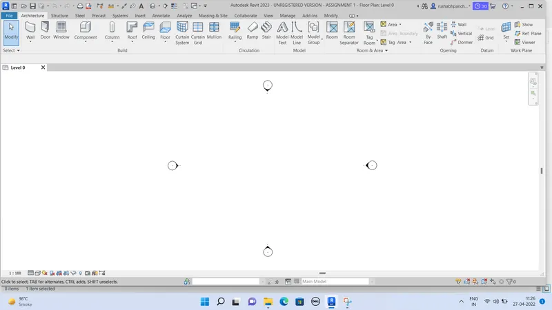
And then click on the ASSIGNMENT NO 1.
By this we can open file by using the file toolbar.
Result –

3.From the architecture / structure toolbar familiarize yourself with options to draw a wall. Create a rectangular layout of walls of about 40’-0” × 35’-0”.
Ans –
REVIT – create walls
Architectural walls inherit the material of other elements to which they are joined. Compound layers in walls wrap at architectural column. This does not apply to structural walls.
Structural walls are used to model vertical load bearing elements in a building. Although, structural walls have many of the same properties as architectural walls. Structural walls have additional properties defined by their configuration and industry standards.
PROCEDURE –
Open REVIT and create new file.
Click the windows button and type REVIT and press enter.
Once the REVIT is open the home tab will appear like this.
Click on the new project.
The dialogue box will appear.
Choose a imperial of architectural drawing template is as follows.
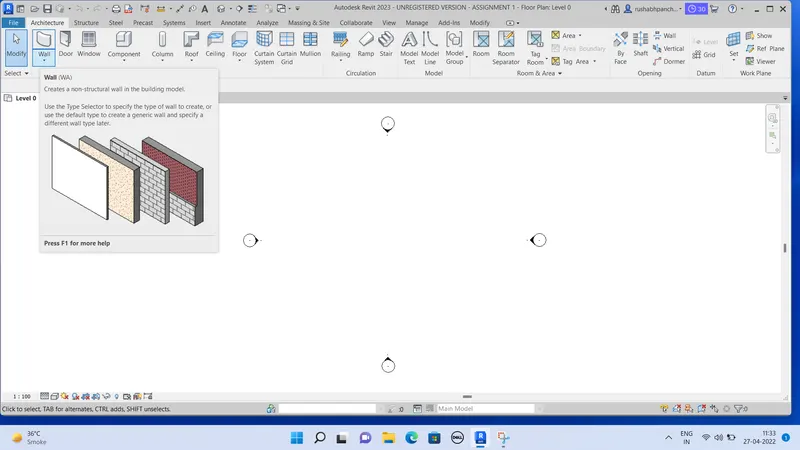
Keep the cursor on the wall on the left corner to view a description of non structural walls.
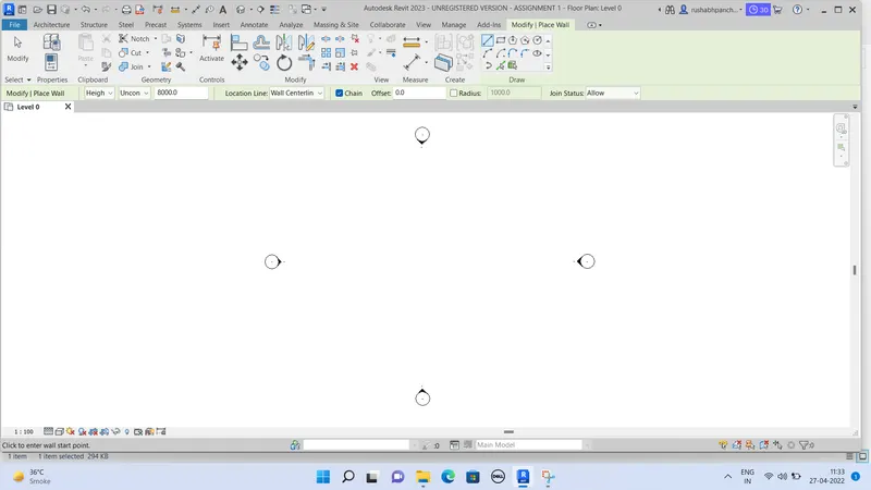
Click the wall – architectural button as shown below.
Changing the units –
Firstly check the units are in mm or inches.
In this project, the dimensions are in feet.
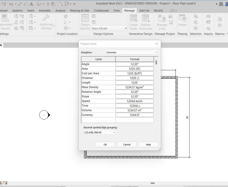
For converting dimensions from mm to feet, click on the “manage” in tool bar.
And click on the project units. And convert length from mm to feet and press ok.
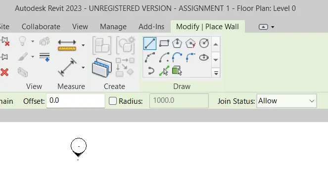
Click on the wall and different tools will appear on screen.
Click on line.
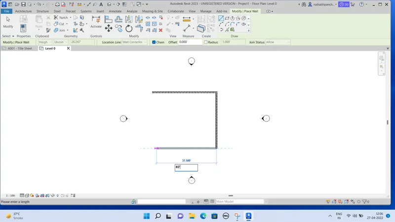
Specify the first point as any point on the model space.
Draw a horizontal wall at a distance of 40’0”.
And on the continuation of that wall, draw a vertical wall in downward direction at a distance of 35’0”.
Again draw a horizontal wall on the continuation of that to the left side at a distance of 40’0”.
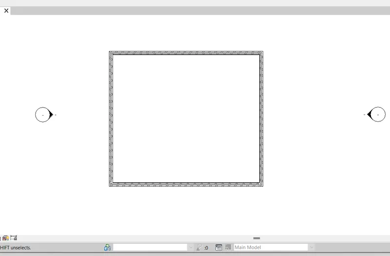
And close the rectangle.
The wall will create.
Result –
4.From the annotate toolbar use the aligned option to add dimensions to the layout.
Ans –
REVIT – Add dimensions.
Annotation of a drawing is very important because it specifies the geometric details of the component annotate objects generally means showing geometric features like length, width and height in this case length of the wall is drawn.
PROCEDURE –
Open REVIT.
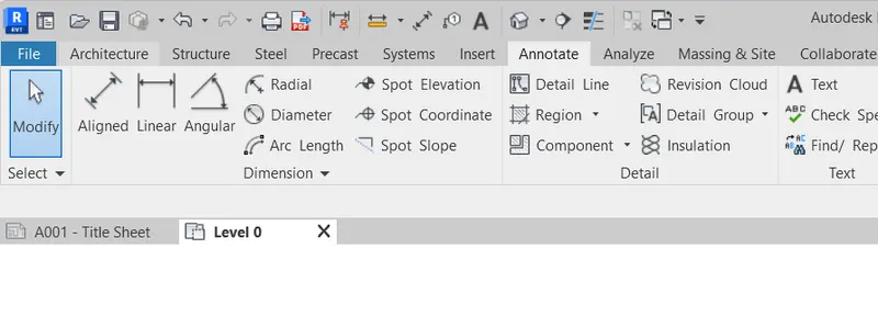
Go to the annotate tab.
Click on the ALIGNED dimensions.
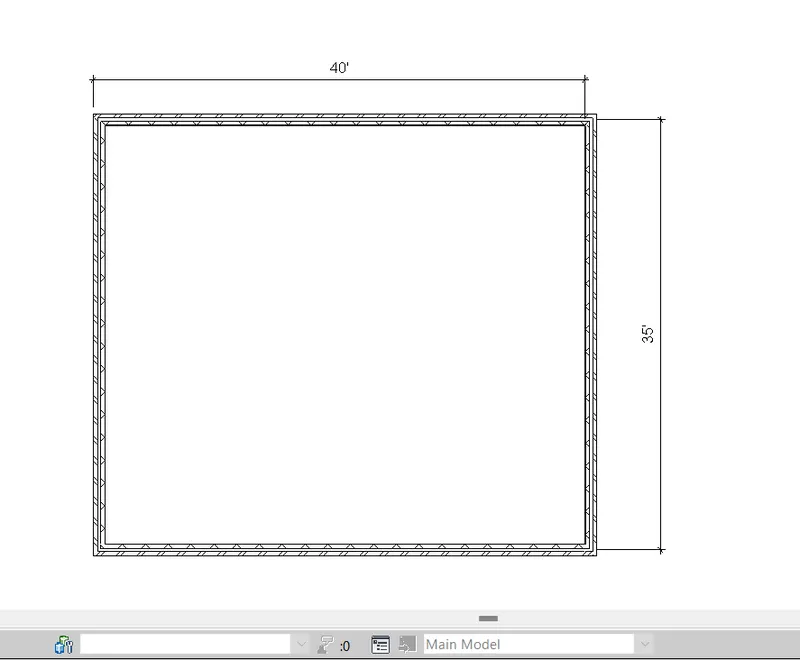
Select the center to center point of the edges of wall.
Give dimensions to horizontal and vertical wall.
The final drawing is shown in the result.
Result –
5.Use the property browser to switch to different wall types.
Ans –
REVIT – Wall properties
The wall type based on the requirement and design changes accordingly.
Different wall types are present in wall families in the project browser of REVIT. Such as a basic wall, curtain walls and stacked walls. The wall type can be changed accordingly in properties.
PROPERTIES –
Open REVIT software.
Open a drawing of the wall which is drawn at last question.
Click on the project browser which is at the bottom left to view different wall types.
Click on the families.
If not available then, type PP in keyboard.
By PP the dialogue box will appear which shows the property browser.
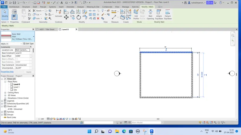
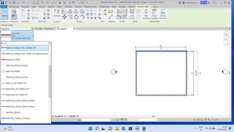
Now, click on the walls to get different types of walls.
click on the wall types to get different sub.
Select wall type and click on the wall in design.
By this, the normal wall will convert in that selected once.
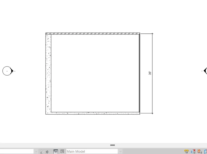
By this procedure, convert all 4 walls in different walls.
Result -
6.Create a 3D view from the view toolbar and save the view with the appropriate name.
Ans –
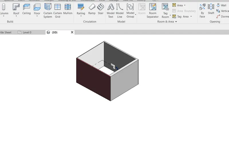
REVIT – 3D view
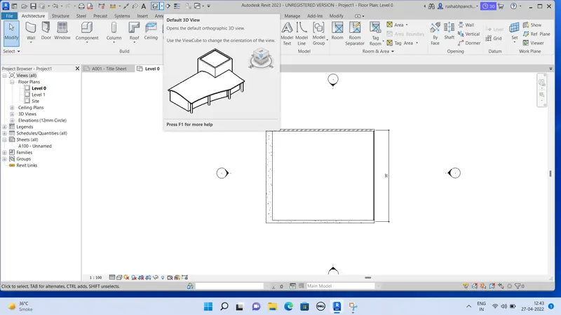
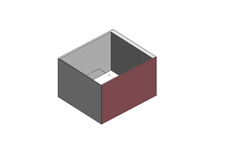
We can convert 2D View to 3D view by the “default 3D view” which is situated on the top.
By the 3D view we can observe the design from all directions such as top, bottom, front and side.
PROCEDURE –
Open REVIT software.
Open a drawing of wall which is drawn in last question.
Now, go to the view tab.
There is a home like tab.
Move the cursor on that tab and “Default 3D view” will appear.
Click on “default 3D View”.
Go to project browser.
Under this 3D view rename the current drawing as 3D WALL.
Result –
7.Navigate through the 3D Model using the view cube. Orbit/pan through the model layout created.
Ans –
REVIT – 3D view cube
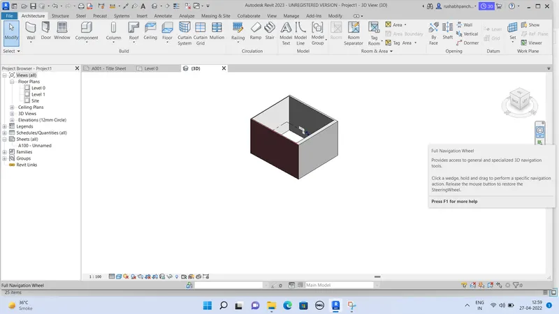
Once a 3D model is created, we can navigate through the model using view cube which is changing to different views such as top, right, front etc and also isometric view.
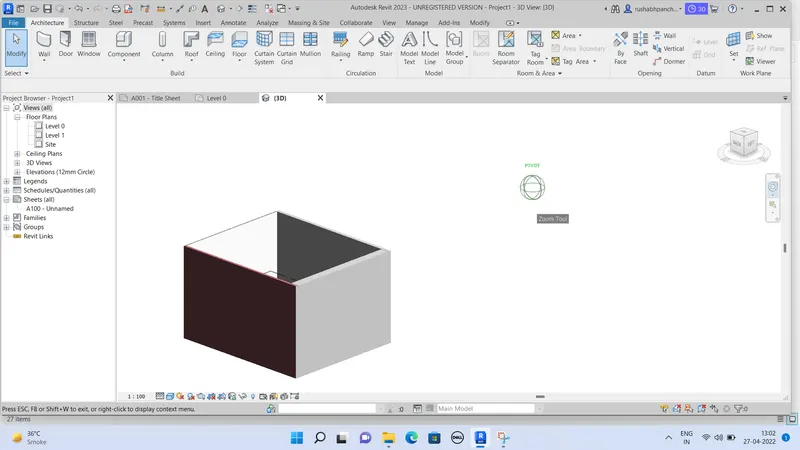
Using orbit/ pan we can also get the view that is most appealing to us when the standard view is not appealing.
PROCEDURE –
Open REVIT software.
Open the last 3D wall drawing which is drawn in last question.
Open the 3D view created above 3D isometric.
From view, change different views as per requirement.
Click on the full navigation wheel which is situated below the 3D view box at the right corner.
Click on the full navigation wheel.
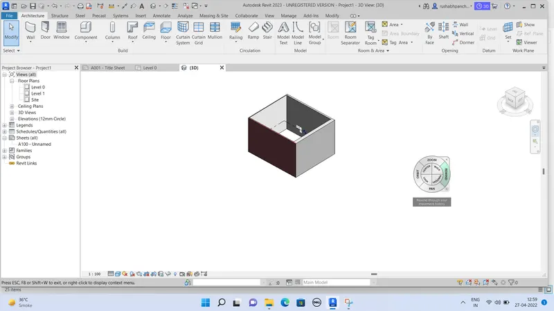
The navigation wheel will appear on screen.
By using the full navigation wheel we can orbit/pan as shown below.
Click on orbit to start 3D orbiting.
Click on pan to move through model space.
Result –
8.Use the visibility settings option below to switch model to shaded, realistic, hidden lines option.
Ans –
REVIT – graphic display setting
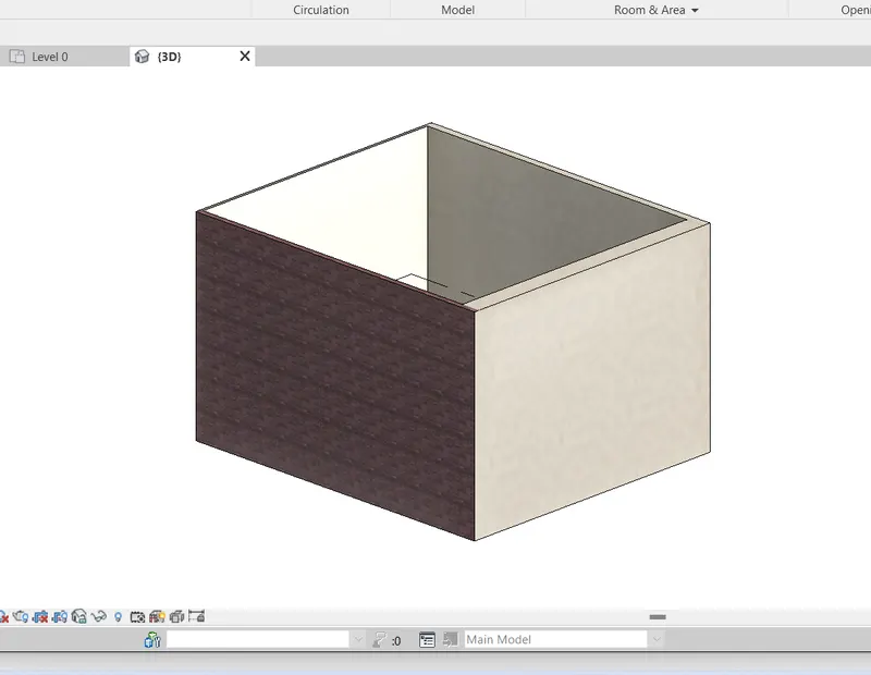
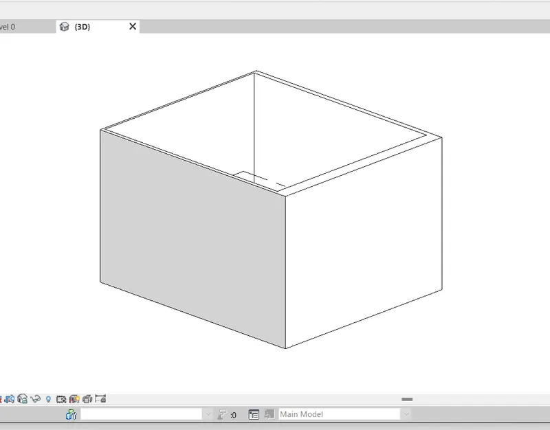
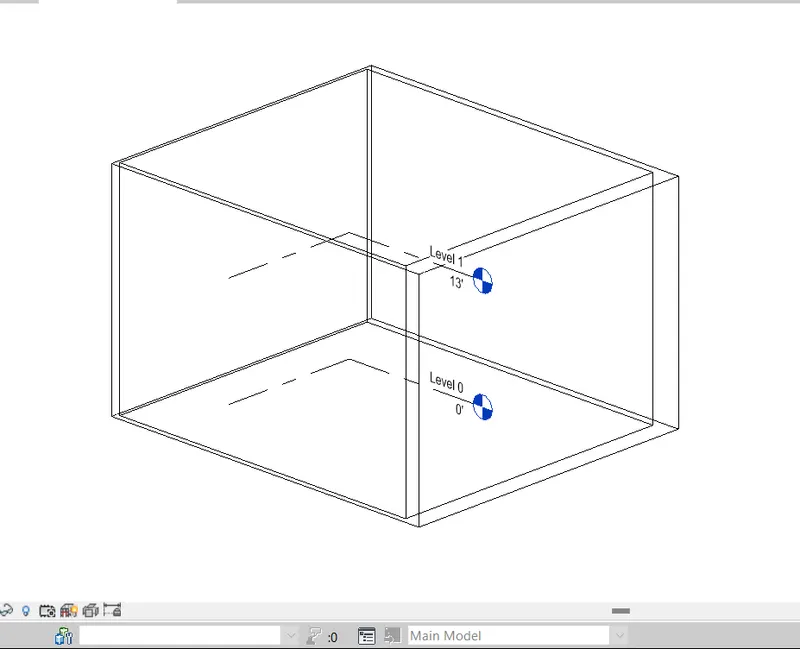
Once a 3D model is created, we create a 2D wireframe model, Which is a transparent model with line which is not aesthetic if many walls and components are present. So it is recommended to change the visibility of 3D to make the lines on the back hidden or shade the wall for a better view.
PROCEDURE –
Open REVIT software.
Open the 3D wall drawing which is drawn in last question.
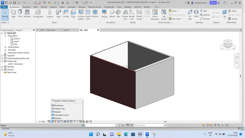
Go to a bottom toolbar and click on visual settings as shown in the below figure.
Different types of views will appear like wireframe, shaded, realistic etc.
Change the perspective view as required.
Result –
9.Turn the sun path on and off to view shadings in the layout created.
Ans –
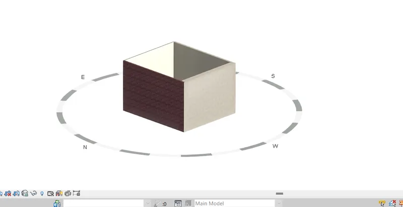
REVIT – Sun path
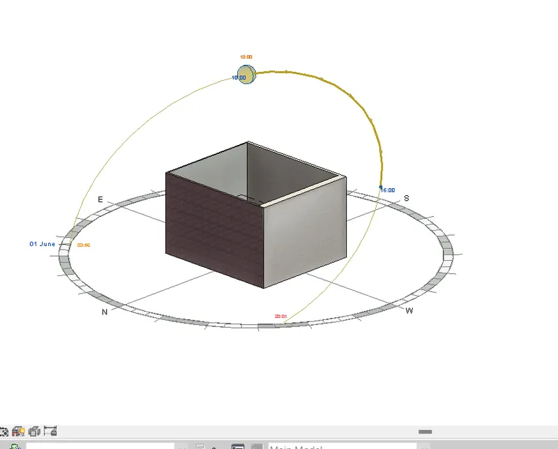
Once a 3D model is created, we create a 2D wireframe model. Sun path decides the shadows and shadings of 3D view. Sun path is generally from east to west, so the time of the day and location affect the shadows formed. In REVIT, we can give the location of the house and time to give an exact sun path to view.
PROCEDURE –
Open REVIT software.
Open the 3D wall drawing which is drawn in last question.
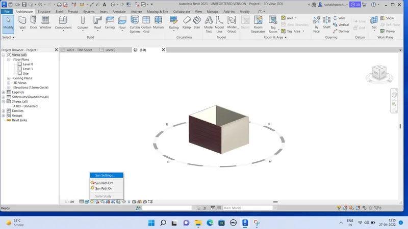
Click on the sun symbol which is situated at bottom toolbar.
Click on that to open sun setting as shown below.
There are some options like sun on and sun off.
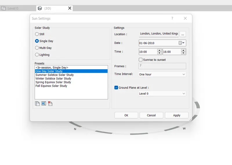
Click on sun on and from dialogue box, set the location as per our requirement.
Click OK to confirm location.
Turn on the sun path.
Also click on single day in solar study and press ok.
Result –
10.Use the manager toolbar to enter project settings, project name, and project issue date ( choose according to your convenience )
Ans –
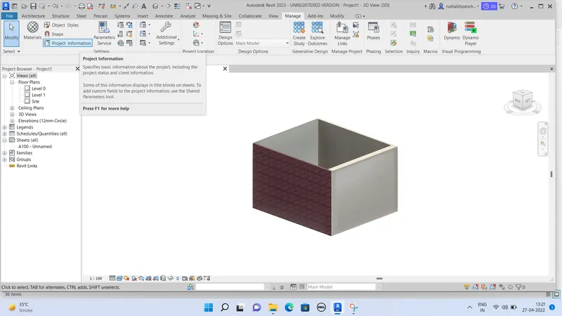
REVIT – project information
By using the project setting, we can give the name and all the information to the project.
PROCEDURE –
Open REVIT software.
Open any previous or new drawing in REVIT.
Go to manage tab which is one of the toolbars.
Click on the project information on the left side.
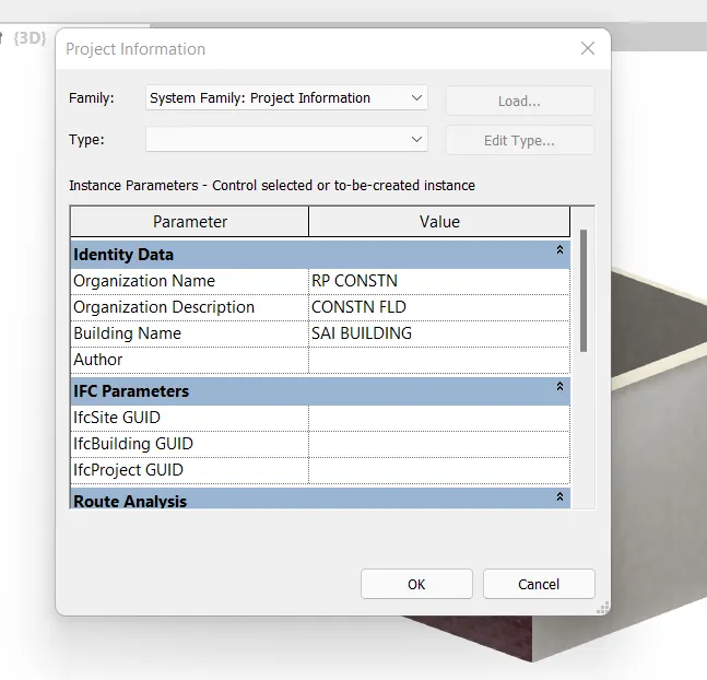
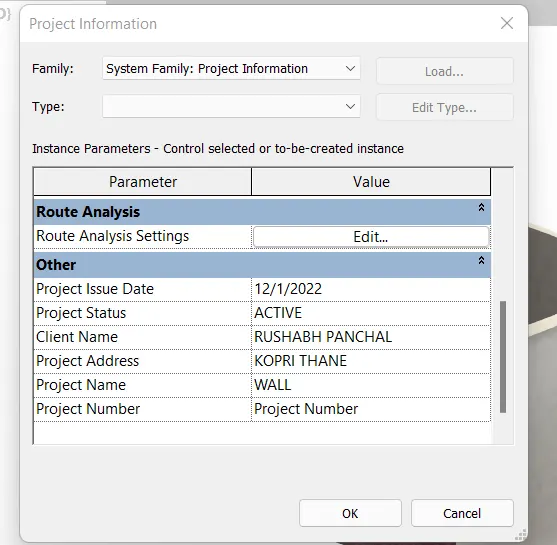
The dialogue box will appear on screen.
Fill all the information about the project like name, company name, date etc.
And press OK.
Result –
11. what is the Analyze toolbar used in REVIT? How it is beneficial for design and modeling
Analyze to b is REVIT consist of tools for detailed analysis of the structures/layout created. An analytical model is created using Analyze tab.
Some of the components of analyze tab are as follows

- Analytical Model:
Adding boundary conditions, types of load such as point line, and area loads, load cases, and load
combinations of point, lines, and area conditions using this toolbar.
- Analytical Model Tools
It contains tools to adjust the analytical model, check for consistency, reset the model and check member supports in this tab
- Spaces & Jones
The toolbar is used to create space separators. Space separators are drown to separate different rooms
of the plan to differentiate the rooms. It also contains a tab to name the space that is separated.
- Reports & Schedules
Reports6 schedules are prepared of the following Heating and cooling loads report
Duct Pressure Loss Report
Pipe Pressure Loss Report • Panel schedules ScheduIe/quantities
5 Check Systems
Check systems for components such as duct pipe, and circuits and showing disconnects
- Color Fill
- Energy Optimization
Energy Optimization for REVIT is a fast, reliable, and scalable tool for better building energy performance.
Analyze tab Energy Optimization panel
Location
Create Energy Model Generate
Optimize
Energy Settings
Energy Optimization for REVIT provides clear guidance and direction towards better building energy performance for the entire design team from concept to detail ancl design to the operation of new and existing buildings
- Route Analysis
Use route analysis to calculate distance and time of travel from one point to another point in the model
- Structural Analysis
Using this toolkit structural designers and engineers con optimize their workflows in the cloud and on the desktop by using the analytical model built in REVIT software by extending the REVIT model to Autodesk Robot Structural Analysis Professional software. or supported third party analysis solutions. Once complete, analysis results can be easily stored and explored in the REVIT environment.
- What are the links that REVIT supports to be linked to the model
In REVIT other models can be linked to the current model that is under production. The linking of models helps to create an optimized and efficient model in REVIT. The link Supports in REVIT are
Link REVIT: Using this link between two REVIT models can be created e., one past and one current file. it specifies the relative locations of the individual buildings on campus or coordinates efforts across disciplines (Architectural, structural, and engineering).
- Link IFC: The Industry Foundation Classes (iFC) data model is intended to describe architecturally, building, and construction industry It is a platform-neutral, open file format specification that is not controlled by a single vendor or group of vendors. Link to an IFC file when you want to perform additional design work in REVIT using the IFC file as a reference.
- Link CAD: When you link a CAD file to a REVIT model, REVIT maintains a link to that Whenever you open the model. REVIT retrieves the current, saved version of the linked file and displays it in the model. Any changes to the linked file are displayed in the model. if the linked file changes while the model is open, reload the file to retrieve the latest changes. This ability to retrieve the latest changes to a CAD file is the difference between linking and importing. When you import a CAD file, REVIT uses the version of the file that you imported. It does not retrieve or display changes to the imported file.
- Link Topography: When a civil engineer or a landscape architect creates topography data for a project and you want to reference it for a building model, you can link the topography to
- Link DWF Markups: When creating construction documents, a typical workflow is to print out a sheet, have it reviewed and marked up by the project architect or other professional, and then return it to the originator of the sheet to have the requested changes made
- Link Decals: Use the Place Decal tool to place images on surfaces of a building model for rendering
- Link Point Cloud: Link a Point Cloud file into the project to provide a highly accurate visual reference of the existing condition of a building or
- Why do you need the Collaborate tab in REVIT? How it supports modeling and its efficiency
REVIT provides several different ways to collaborate with team members who are also using the software.
Helps link multiple REVIT models together, simultaneously allowing other team members to work in the background.
Users on the same local area network (LAN) con work together in the same REVIT model using REVIT Work Sharing. . When collaboration needs to occur among users who are not in the same geographic location, use REVIT Server or REVIT Cloud Work sharing
REVIT Server connects offices that share a network but are not in the same geographic location.
REVIT Cloud Work—sharing is a cloud—based service thot allows any REVIT users inside or outside a network to collaborate on a
REVIT model.
REVIT Cloud Work—sharing helps in modeling with efficiency
As the REVIT Cloud Work-sharing service helps to author REVIT models in the cloud concurrently with other team members.
Before REVIT users collaborate on a model in the cloud, you must upload the model from REVIT to BIM 360 Document Management.
During the upload process, the following events occur:
If the model does not yet have work—sharing enabled, work- sharing is automatically enabled, the REVIT model is uploaded to the BIM
360 project and a locally—cached version is created on your computer.
If the model is already work shared, the REVIT model is uploaded to the BIM 360 project, and a locally- cached version is created on your computer.
As alternatives to using REVIT Cloud Work-sharing you can use REVIT Server to collaborate across a wide area network
based work—sharing to collaborate across a local area network (LAN)