Internal Geneva Mechanism
Objective:
- Prepare 3d model of driver and driven part of internal geneva mechanism.
- Create the assembley of a geneva mechanism.
- Simulation of the geneva mechanism at 10 rpm and 20 rpm.
- Compare the graph between precise contact and non-precise contact force.
- Compare the graph of the angular velocity of the driver and the driven at 10 and 20 rpm.
- Get the graph of angular displacement.
Introduction:
Geneva mechanism is commonly used indexing mechanism where an intermittent motion is required.
The Inverse Geneva mechanism, which is a variation of the Geneva mechanism, is used where the wheel has to rotate in the same Direction as crank. It requires less radial space and the locking device can be a circular segment attached to the crank that locks by wiping against a built up rim on the periphery of the wheel.
The design and fabricating of a conventional Geneva mechanism is generally simple and inexpensive because there is no specially curved profile on any of the components except straight lines and circular arcs. However, due to the discontinuity of the acceleration at the beginning and ending positions, the shortcoming of using conventional Geneva mechanism is the large impact when the driving crank engages and disengages with the wheel slot.
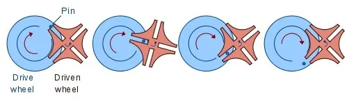
CLASSIFICATION OF GENEVA MECHANISM
- EXTERNAL GENEVA MECHANISM:
- INTERNAL GENEVA MECHANISM:
- SPHERICAL GENEVA MECHANISM:
How Geneva Mechanism Works?
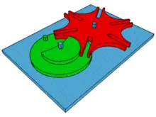
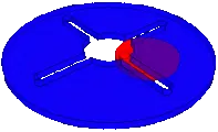
Model
:
Results and plots:1.At speed of 10rpm of the driver wheel(60fps)
a.Contact force between driver and driven wheel without precise contact.
b.Contact force between driver and driven wheel with precise contact.
c.Angular displacement of driven wheel.
d.Angular velocity of the driven wheel.
2.At the speed of 20rpm of the driver wheel(120fps):
a.Contact force between driver and driven wheel without precise contact.
b.Contact force between driver and driven wheel with precise contact.
c.Angular displacement of driven wheel.
d.Angular velocity of the driven wheel.
Image showing precise contact:
Animation youtube link:https://youtu.be/uVFNKQPODEs
Result:If the rpm of the driver wheel increases then the angular displacement of the driven wheel increases according to the time. the mechanism has a speed ration of 4:1 which means that the driven wheel only rotates once while the driver wheel rotates 4 times.when comparing the conract forces between precise and without precise contact it shows that if the precise force is considered then the value of the contact force will increase and give much accurate result.Bt showing the angular displacement graph of the driven wheel it is observed thatfor a few second driven wheel will be at rest position and again revolve upto 90 degrees and this process continue all along the mechanism.By showing the angular velocity graph some jerk will be observed at the begning of the motion of the driven wheel of initial contact between driver and the driven wheel.
The parts files and the assembley files ,plots and graphs are here in the drive link: https://drive.google.com/drive/folders/1ZpFc_qquZJjSMu9gRZe6eh_TkvYmCcCx?usp=sharing