INDUCTION MOTOR CHARACTERSTICS - 2
INDUCTION MOTOR CHARACTERSTICS - 2
AIM:
- To study on the Equivalent Circuit network of Induction Motor.
- To evaluate for the ratio of starting torque at Half Voltage & Rated Voltage.
- To script a MATLAB file for an Induction Motor with Torque-Speed Characteristics using Frequency Control Method.
- To study the operation of BLDC Motor.
INTRODUCTION:
Induction Motor
An Induction motor or Asynchronous motor is an AC electric motor in which the electric current in the rotor needed to produce torque is obtained by electromagnetic induction from the magnetic field of the stator winding. An induction motor can therefore be made without electrical connections to the rotor. An induction motor's rotor can be either wound type or squirrel-cage type. They are self-starting, reliable and economical. Single-phase induction motors are used extensively for smaller loads, such as household appliances like fans. Although traditionally used in fixed-speed service, induction motors are increasingly being used with variable-frequency drives (VFD) in variable-speed service. VFDs offer especially important energy savings opportunities for existing and prospective induction motors in variable-torque centrifugal fan, pump and compressor load applications. Squirrel cage induction motors are very widely used in both fixed-speed and variable-frequency drive applications.
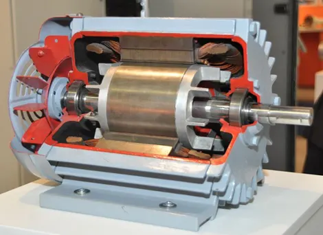
In both induction and synchronous motors, the AC power supplied to the motor's stator creates a magnetic field that rotates in synchronism with the AC oscillations. Whereas a synchronous motor's rotor turns at the same rate as the stator field, an induction motor's rotor rotates at a somewhat slower speed than the stator field. The induction motor stator's magnetic field is therefore changing or rotating relative to the rotor. This induces an opposing current in the induction motor's rotor, in effect the motor's secondary winding, when the latter is short-circuited or closed through an external impedance. The rotating magnetic flux induces currents in the windings of the rotor, in a manner similar to currents induced in a transformer's secondary winding(s).
The induced currents in the rotor windings in turn create magnetic fields in the rotor that react against the stator field. The direction of the magnetic field created will be such as to oppose the change in current through the rotor windings. The cause of induced current in the rotor windings is the rotating stator magnetic field, so to oppose the change in rotor-winding currents the rotor will start to rotate in the direction of the rotating stator magnetic field. The rotor accelerates until the magnitude of induced rotor current and torque balances the applied mechanical load on the rotation of the rotor. Since rotation at synchronous speed would result in no induced rotor current, an induction motor always operates slightly slower than synchronous speed.
--------------------------------------------------------------------------------------------------------------------------------
- Equivalent Circuit of Induction Motor
An induction motor is a well-known device which works on the principle of transformer. So, it is also called the rotating transformer. That is, when an EMF is supplied to its stator, then as a result of electromagnetic induction, a voltage is induced in its rotor. So, an induction motor is said to be a transformer with rotating secondary. Here, primary of transformer resembles stator winding of an induction motor and secondary resembles rotor.
The induction motor always runs below the synchronous or full load speed and the relative difference between the synchronous speed and speed of rotation is known as slip which is denoted by s.
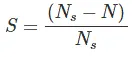
Where, Ns is synchronous speed of rotation which is given by-
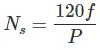
Where, f is the frequency of the supply voltage.
P is the number of poles of the machine.
The equivalent circuit of any machine shows the various parameter of the machine such as its Ohmic losses and also other losses.
The losses are modelled just by inductor and resistor. The copper losses are occurred in the windings so the winding resistance is taken into account. Also, the winding has inductance for which there is a voltage drop due to inductive reactance and also a term called power factor comes into the picture.
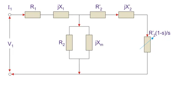
Here, R1 is the winding resistance of the stator.
X1 is the inductance of the stator winding.
Rc is the core loss component.
Xm is the magnetizing reactance of the winding.
R2/s is the power of the rotor, which includes output mechanical power and copper loss of rotor.
R2’ is the rotor winding resistance with referred to stator winding.
X2’ is the rotor winding inductance with referred to stator winding.
R2(1 – s) / s is the resistance which shows the power which is converted to mechanical power output or useful power. The power dissipated in that resistor is the useful power output or shaft power.
- Input power to stator- 3 V1I1Cos(Ɵ).
- Where, V1 is the stator voltage applied.
- I1 is the current drawn by the stator winding.
- Cos(Ɵ) is the stator power stator.
- Rotor input = Power input- Stator copper and iron losses.
- Rotor Copper loss = Slip × power input to the rotor.
- Rotor Copper loss = Slip × power input to the rotor.
Torque Equation
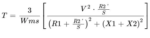
Where,
T – Torque (Nm)
Wms – (rad/s)
V – Per phase voltage
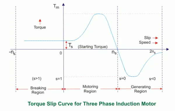
S = 0 to 1, S = 0 Motor is running at synchronous Speed
S = 1 Motor is stand still.
--------------------------------------------------------------------------------------------------------------------------------
- Starting Torque at Half Voltage & Rated Voltage of Induction Motor
Consider,
- 3 Phase, 50Hz Induction Motor
- X1 = X2 = 0.1
- R1 = R2 = 0.1
- To Find Starting Torque @
- Half Voltage & Half Frequency (V/2, f/2)
- Rated Voltage & Rated Frequency (V, f)
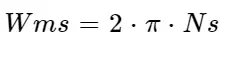
Eliminating the Constants in both cases,
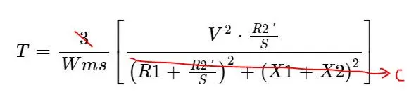
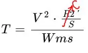
Substituting the remaining terms to find ratio of Rated Torque (Tr) to Half Voltage (Th),
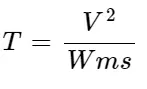
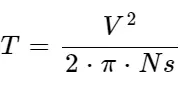
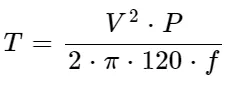
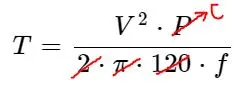
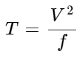
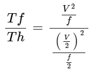
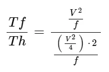
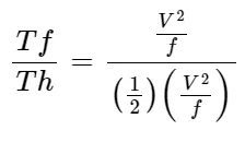
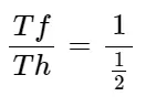
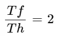
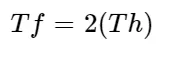
Therefore, Starting Torque at Full Voltage & Frequency is twice the Starting Torque @ Half Voltage & Frequency. i.e. Ratio = 0.5
-------------------------------------------------------------------------------------------------------------------------------
- To script a MATLAB file for an Induction Motor with Torque-Speed Characteristics using Frequency Control Method.
clear all
close all
clc

% Speed-Torque Relation

V=400/sqrt(3);   % Per Phase Voltage
N_ph=3;           % Number of Phases
poles=4;          % Number of Poles
fe=[50:25:150];            % frequency range
R1=0.15;
R2=0.15;
X1=0.1;
X2=0.1;         % Resistance & Inductance Values for Stator & Rotor

% To calculate the synchronous speed of Motor

for i=1:length(fe)
    omega=(4*pi*fe(i))/poles;
    N_s=(120*fe(i))/poles;

for n=1:200
    S(n)=n/200; %slip
    rpm(n)=N_s*(1-S(n));
    Zeq=R1+R2*(1-S(n)/S(n))+(X1+X2);

    T(n)=3*((V^2)*(R2/S(n)))/(omega*((R1+(R2/S(n))^2))+((X1+X2)^2)); %Electromagnetic Torque
end

plot(rpm,T)
hold on
grid on
xlabel("Speed(RPM)")
ylabel("Torque(Nm)")
legend('50Hz','75Hz','100Hz','125Hz','150Hz')
end
PROGRAM EXPLANATION
- 3-Phase, 4-Poles, 400 Volts Induction Motor is considered for simulation.
- Since this is Frequency Control method, an array of different operating frequencies is created.
- A nominal value for Stator & Rotor Resistance & Inductance is entered.
- For the elements present in array of operating frequencies, Synchronous Speeds are calculated.
- Slip is defined in the range of 0 to 1 and Motor rotating Speed is calculated using suitable formulae.
- Similarly, Torque has been calculated and Torque-Speed Curves at different Operating frequencies are plotted.
Results
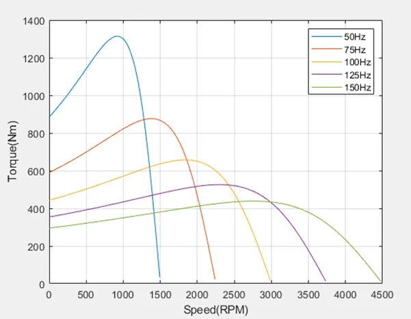
- It can be observed from the plot, that with increase in the frequency the Motor Speed is increasing.
- Motor speed is proportional to the Operating Frequency.
- But the Maximum Torque is reducing with Increase in Speed.
- In order get an Optimal Working range, along with Frequency the Supply Voltage has to be altered.
- e. Voltage-Frequency ratio control method will be a best alternate to this method.
--------------------------------------------------------------------------------------------------------------------------------
- To study the operation of BLDC Motor.
A brushless DC electric motor (BLDC motor or BL motor), also known as electronically commutated motor (ECM or EC motor) and synchronous DC motors, are synchronous motors powered by direct current (DC) electricity via an inverter or switching power supply which produces electricity in the form of alternating current (AC) to drive each phase of the motor via a closed loop controller. The controller provides pulses of current to the motor windings that control the speed and torque of the motor. This control system replaces the commutator (brushes) used in many conventional electric motors.
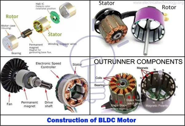
Unlike conventional brushed type DC motor, wherein the brushes make the mechanical contact with commutator on the rotor so as to form an electric path between a DC electric source and rotor armature windings, BLDC motor employs electrical commutation with permanent magnet rotor and a stator with a sequence of coils. In this motor, permanent magnet (or field poles) rotates and current carrying conductors are fixed.
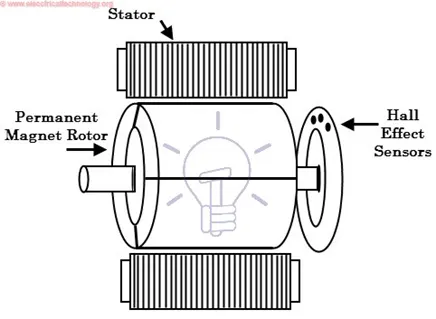
Stator of a BLDC motor made up of stacked steel laminations to carry the windings. These windings are placed in slots which are axially cut along the inner periphery of the stator. These windings can be arranged in either star or delta. However, most BLDC motors have three phase star connected stator.
BLDC motor incorporates a permanent magnet in the rotor. The number of poles in the rotor can vary from 2 to 8 pole pairs with alternate south and north poles depending on the application requirement. In order to achieve maximum torque in the motor, the flux density of the material should be high. A proper magnetic material for the rotor is needed to produce required magnetic field density.
Hall sensor provides the information to synchronize stator armature excitation with rotor position. Since the commutation of BLDC motor is controlled electronically, the stator windings should be energized in sequence in order to rotate the motor. Before energizing a particular stator winding, acknowledgment of rotor position is necessary. So, the Hall Effect sensor embedded in stator senses the rotor position.
Most BLDC motors incorporate three Hall sensors which are embedded into the stator. Each sensor generates Low and High signals whenever the rotor poles pass near to it. The exact commutation sequence to the stator winding can be determined based on the combination of these three sensor’s responses.
Working Principle & Operation of BLDC Motor
BLDC motor works on the principle similar to that of a conventional DC motor, i.e., the Lorentz force law which states that whenever a current carrying conductor placed in a magnetic field it experiences a force. As a consequence of reaction force, the magnet will experience an equal and opposite force. In case BLDC motor, the current carrying conductor is stationary while the permanent magnet moves.
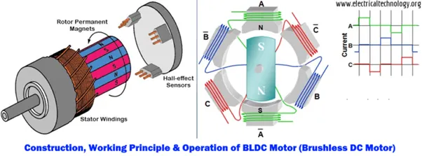
When the stator coils are electrically switched by a supply source, it becomes electromagnet and starts producing the uniform field in the air gap. Though the source of supply is DC, switching makes to generate an AC voltage waveform with trapezoidal shape. Due to the force of interaction between electromagnet stator and permanent magnet rotor, the rotor continues to rotate.
With the switching of windings as High and Low signals, corresponding winding energized as North and South poles. The permanent magnet rotor with North and South poles align with stator poles causing motor to rotate.
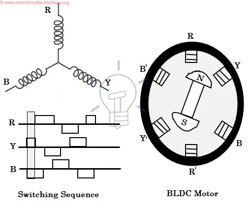
Based on this signal from sensor, the controller decides particular coils to energize. Hall-effect sensors generate Low- and High-level signals whenever rotor poles pass near to it. These signals determine the position of the shaft.
The electronic controller circuit energizes appropriate motor winding by turning transistor or other solid-state switches to rotate the motor continuously. The figure below shows the simple BLDC motor drive circuit which consists of MOSFET bridge (also called as inverter bridge), electronic controller, hall effect sensor and BLDC motor.
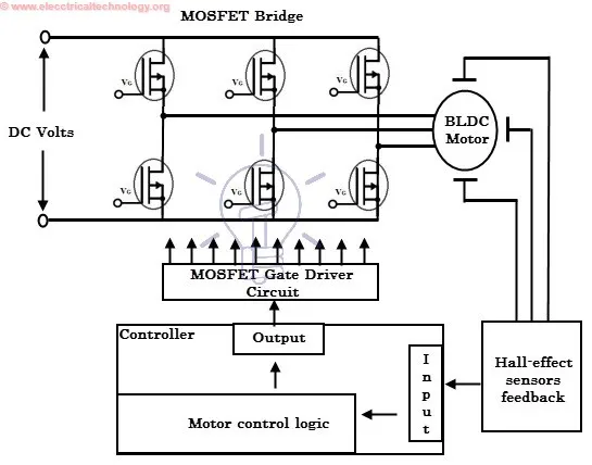
In addition to the switching for a rated speed of the motor, additional electronic circuitry changes the motor speed based on required application. These speed control units are generally implemented with PID controllers to have precise control. It is also possible to produce four-quadrant operation from the motor whilst maintaining good efficiency throughout the speed variations using modern drives.
**************************************************************************************************************************************************************************************