INDUCTION MOTOR CHARACTERISTICS - II
INDUCTION MOTOR CHARACTERISTICS - II
AIM –
- Discuss about equivalent circuit network of Induction Motor MATLAB Model.
- 3 Phase 50 Hz. Induction Motor, represented by equivalent circuit constants X1 = X2 = 0.1 Ohm. & R1 = R2 = 0.2 Ohm. Is operated half at rated voltage and frequency. Calculate the ratio of starting torque at half voltage and frequency to rated values.
- Make a MATLAB script file which will plot speed torque characteristics for frequency control method.
- Explain in brief – Operation of BLDC Motor.
Q. 1) Discuss about equivalent circuit network of Induction Motor MATLAB Model.
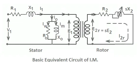
Given below the equivalent circuit of an Induction Motor with stator & Rotor circuits separated. The frequency of currents in both circuits are different. Suppose the frequency of the rotor circuit is f2 & frequency of the stator circuit is f1 & let the slip value will be s.
f2 = s*f1
this means the frequency of the rotor circuit varies by a factor of s with respect to f1.
In the above figure, V1 is applied voltage to the stator E1 is the induced emf. R1 & X1 is the stator resistance respectively. l1 is the current flowing through the stator circuit, l0 is the no load current which splits into lm which is magnetizing component & lw is the core loss current. Xo is the pure inductive reactor and Ro is the non-inductive resistor.
E2 is induced emf in the rotor circuit, R2 & X2 is the rotor resistance and reactance respectively.
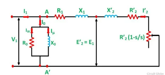
Given below is the equivalent circuit with reference to the stator. This is made possible by making the frequencies of stator and rotor circuits equal. Here, the resistance is split into two parts – R’2 &R’2 (1 –s / s) is the electrical equivalent of the mechanical power used up by the rotor and R’2 is the pure copper loss of rotor.
An induction motor consists of a stationary component called the stator and a rotary component called the rotor. The stator consists of 3 coiled windings supplied with 3 phase AC power which is wound around the stacks if thin, high permeable laminations in a cast iron or steel frame changing the frequency of 3 phase power supply (i.e. sinusoidal supply voltage and current phasors) will generate the rotating magnetic field. This induces an emf and therefore the current in the rotor when the magnetic field interacts with the rotor via electromagnetic induction. But now the rotor is current carrying conductor in the rotating magnetic field, it will experience electromagnetic force producing a torque via the motor effect.
Since the emf is induced in the rotor, there will be current flowing through it and this is denoted as I2.
The induced emf in the rotor as a result of electromagnetic induction is also referred as ‘back emf’ because it acts in the opposite direction to the direction of the 3 phase voltage across the coil windings in the stator.
The magnetizing inductance, lm is required at the air gap because across it is the boundary between stator and the rotor, the stator will produce the rotary magnetic field & it needs to cross the air gap to interact with the rotor to excite it to produce the torque. So the magnetizing inductance, lm is needed to cross the air gap.
Xm, X1, X2 all represent inductance values, resistance is a form of opposition that the electronic components exhibit to the passage of current through them due to their capacitance or inductance properties.
Operation –
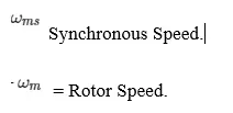
The speed of the rotating magnetic field is also known as the synchronous speed and it is dependent upon the frequency of 3 phase power supply & no. of poles of the inductance motor. So the frequency of the 3 phase power supply is proportional to the synchronous speed and also the motor speed.
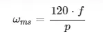
p = No. of Poles.
f = Frequency of 3 –Phase power supply.
This can be also expressed as,
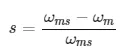
Where,
The torque that is produced by the rotor of the induction motor can be expressed mathematically as so –
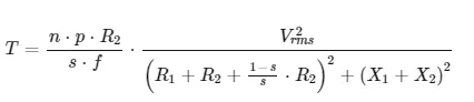
n = No. of Poles.
X1 = Stator Inductance.
X2 = Rotor Inductance.
Vrms = Root Mean Square Voltage.
The block can be modified in terms of the parameters mentioned below the equivalent circuit model or in terms of motor ratings. From the block we can see that there are 2 mechanical ports; C & R, when the block is used in simulation, a positive torque is produced acting from the ports.
The block 2 has 2 thermal ports, one for each winding and they are mainly used to simulate the copper resistance losses that occur which are in the form of heat energy. To see these ports, we need to right click on the block and from the options select Simscape& then the block choices nd then show thermal port.
While the simplified Induction Motor block can model the torque speed characteristics of an Induction Motor there are still limitations that it has. For instance, it doesn’t model the starting mechanism for a single phase induction motor. Another limitation is that if the block is modelled in terms of motor rating parameters, then the equivalent circuit model parameters are derived by assuming that the magnetizing inductance term, lm is negligible. Hence, the effect of the magnetizing inductance term won’t be included in the simulation.
When circuit is referred to the stator it will look like –
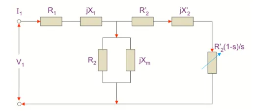
Here,
The rotor winding resistance is referred to the stator winding.
X2’ is the rotor winding inductance.
R2 (1 –s) / s is the resistance which shows the power which is converted to mechanical power. The power dissipated in the resistor is the useful power output or shaft power.
Now,
Zeq = (R1 + R’2(1-s) / s) + j (X1 + X’2)
ls = V1 / Zeq
Putting the value of Zeq we get,
ls = V1 / [R1 + R’2(1 –s) /s + j (X1 +X‘2]
ls = |ls| = V1 / [R1 + R’2(1 –s)/s ^2 + j (X1 + X’2) ^2]
P = V1ls cos 2 = (V1^2)(R’2(1-s)/s) / [R1 + R’2(1-s)/s)^2 + (X1 + X’2)^2]
Torque equation is given by,
T = P/ Ws
T = (V1^2) (R’2/s)/Ws [R1 = R’2/s^2+(X1 +X’2) ^2]
The above equation is the torque equation of the Induction Motor.
Induction Motor MATLAB Model –
Powertrain Blockset / Propulsion / Electric Motors.
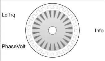
The Induction Motor Block, implements 3 Phase Induction Motor. The block used 3 Phase Input Voltages to regulate the 3 Phase currents, allowing control of motor torque / speed.
Three Phase Sinusoidal Model Electrical System –
The block implements equations that are expressed in a stationary rotor reference (qd) Frame. The d-axis aligns with the a – axis. All quantities in the rotor reference frame are referred to the stator.
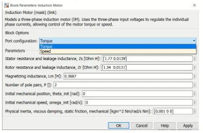
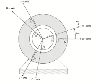
Q. 2) 3 Phase 50 Hz. Induction Motor, represented by equivalent circuit constants X1 = X2 = 0.1 Ohm. & R1 = R2 = 0.2 Ohm. Is operated half at rated voltage and frequency. Calculate the ratio of starting torque at half voltage and frequency to rated values.
No. of Phases = 3
Rated Frequency = 50 Hz.
Stator Inductance (X1) = 0.1 Ohms.
Rotor Inductance (X2) = 0.1 Ohms.
Stator Resistance (R1) = 0.2 Ohms.
Rotor Resistance (R2) = 0.2 Ohms.
We need to find the starting torque at the half rated voltage and frequency to the same at the rated voltage & frequency –
The given data with respect to the equation is –
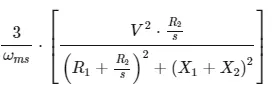
Since we are only required to find out the starting torque hence, we can eliminate the slip term ‘S’. this is because at the starting torque, the motor speed is ‘0’ so the synchronous speed terms will cancel each other out that means the slip will take a maximum value of 1.
The equation for slip is -
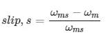
So we can rewrite the torque equation omitting the slip term ‘s’, since it’s equal to 1.
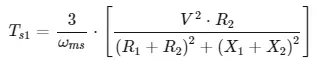
The starting torque is given by the equation –
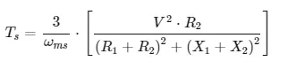
Now we can use this equation to find out the starting torque at the half rated and full rated condition.
Synchronous Speed –
The formula to find out synchronous speed is –
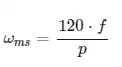
Where,
f = Frequency.
p = No. of Poles.
Let us consider the no. of poles = n
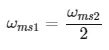
Let the half rated synchronous speed = `omega`ms1.
Let the half rated synchronous speed = `omega`ms2.
Half rated frequency = Rated Frequency / 2 = 50/2 = 25 Hz.
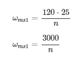
Rated Frequency = 50 Hz.
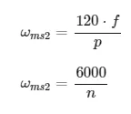
Since, we know that the rated synchronous speed is double the half rated synchronous speed, we can express the latter in terms of the former.
Calculation of starting torque at half rated condition –
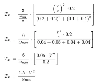
As now we have expressed the half rated synchronous speed in terms of the rated synchronous speed, we will substitute the expression in the place of the synchronous speed term when calculating the half rated starting torque.
Since we are also varying the voltage between the 2 conditions, let’s assume that the rated voltage is V nd that the half rated voltage is V / 2.
Let the half rated starting torque Ts1.
Substituting the expression for synchronous speed in terms of rated synchronous speed –
Calculation of starting torque at full rated condition –
In this condition we will use full rated voltage, V, the full rated frequency of 50 Hz. And the full rated synchronous speed to find the starting torque. Here we will substitute the synchronous speed at the full rated condition : ms2.
Let the starting torque under full rated condition be Ts2.
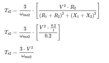
Comparison of starting torque at both conditions –
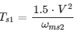
The starting torque at the half rated condition is:
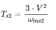
The starting torque at the full rated condition is:
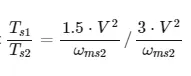
So the ratio of –
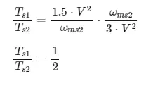
Therefore, the ratio of the starting torque at the half rated condition to the full rated condition is ½ or 0.5.
Q. 3) Make a MATLAB script file which will plot speed torque characteristics for frequency control method.
Programme Explanation –
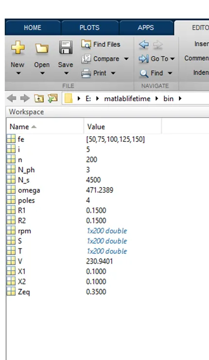
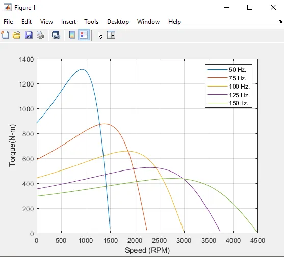
3 Phase 4 Pole 400 Volts Induction Motor is considered for Simulation.
As this is frequency control method, an array of different operating frequencies is created.
A Nominal Value of Stator & Rotor inductance is entered.
For the elements present in an array of operating frequencies, synchronous speeds are calculated.
Slip is defined as the range of 0 to 1 and motor rotating speed is calculated using suitable formulas.
Similarly, Torque has been calculated & Torque –Speed Curves at different operating frequencies are plotted.
clear all
close all
 clc

 % Speed - Torque Relation
 V = 400/sqrt(3);
 N_ph = 3;
 poles = 4
 fe = [50:25:150];
 R1 = 0.15;
 R2 = 0.15;
 X1 = 0.1;
 X2 = 0.1;
 % To Calculate Synchrnous Speed of the Motor
 for i = 1:length(fe)
     omega = (4*pi*fe(i))/poles;
     N_s = (120*fe(i))/poles;
     for n = 1:200
         S(n) = n/200;
         rpm(n) = N_s*(1-S(n));
         Zeq = R1 + R2*(1-S(n)/S(n)) + (X1 +X2);
         T(n) = 3*((V^2)*(R2/S(n)))/(omega*((R1+(R2/S(n))^2))+((X1+X2)^2));
     end
     plot(rpm,T)
     hold on
     grid on
     xlabel('Speed (RPM)')
     ylabel('Torque(N-m)')
     legend('50 Hz.','75 Hz.','100 Hz.','125 Hz.','150Hz.')
 end
Q. 4) Explain in brief – Operation of BLDC Motor.
A BLDC Motor stands for Brushless D.C. Motor. It is synchronous motor that is powered by D.C. Power Supply via an inverter which produces an AC Power Supply. Conventional D.C. Motor were constructed with brush contacts found on the outside of the commuter. Over time, the brush contacts of conventional D.C. Motors experience wear & tear & can even cause sparking due to high friction between the Brush & Commuter. So the brush type D.C. Motor was considered to be unsuitable for applications requiring high durability & long life. It was eventually replaced with the improved design of BLDC motor.
Construction –
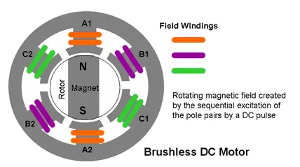
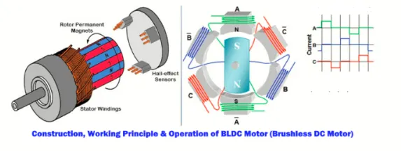
The rotor of the BLDC motor is a permanent magnet with a north & south pole. The stator consists 3 sets of 2 coil windings, which for example can be called A, B, C. BLDC motors can be of outrunner design / inrunner design. In the outrunner type, the stator surrounds the rotor. a D.C. supply is given to one set of coil windings causing them to get energized and this produces magnetic field. One end of the set of windings will be north pole and the other end becomes south pole. The interaction between the electromagnetic field, exerts a force on the rotor to rotate producing torque.
- Inrunner Design –
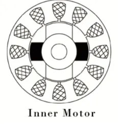
In this design the rotor is located in the centre of the motor and the stator winding surround the rotor. As the rotor is located in the core, rotor magnet don’t insulate heat inside & heat get dissipated easily. Due to this reason, inner rotor designed motor produces a large amount of torque.
Outrunner Design –
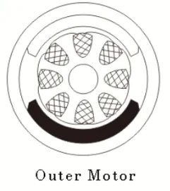
In this design the rotor surrounds the winding which is located in the core of the motor. The magnets in the rotor trap the heat of the motor inside and don’t allow to dissipate from the motor. Such type of designed motor operates at lower rated current and has low cogging torque.
Working –
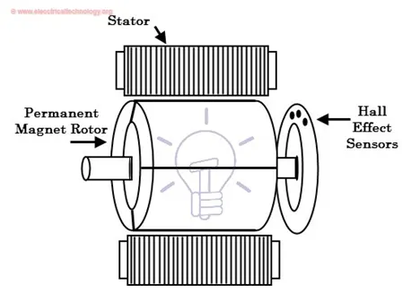
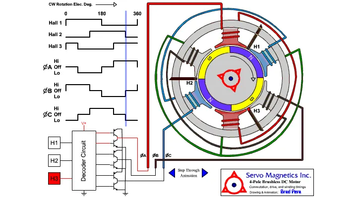
The 2 main performance parameters of a BLDC are the back emf constant i.e. speed constant & motor constant i.e. Torque Constant. The amount of power that can be supplied to a BLDC is limited by a amount of heat dissipation. This is because the high heat can damage the winding insulation of the coils & can also weaken the permanent magnets of the rotor.
The BLDC motor generates maximum torque under when stationary and decreases linearly as the rotor velocity increases. The efficiency of the BLDC motor is greatest in no load & low load condition. However, the conversion from electrical energy to mechanical energy is more efficient in BLDC motor for several reasons. They are as follows -
- The frequency of the switching electricity is solely dependent on the position of the rotor so that power is supplied at the right time & at the right place. So the electronic control of the BLDC motor makes them more efficient and power saving than the brush type D.C. Motor.
- Absence of brush contacts makes the BLDC Motor have lesser mechanical losses sue to friction that would otherwise exist between the brushes & commutator. This also makes them lighter than the brush type D.C. Motor & provide the same power output giving the BLDC motor high power to weight ratio.
- There is no winding on the rotor, the windings are supported by housing and they can be cooled by the conduction when heat builds up. This can prevent the BLDC motor from getting too hot & damaging the winding insulation & weakening the permanent magnets. Also the internal construction of the BLDC motor can be protected from the entry of dirt and other foreign matter.
- Under high mechanical loads, BLDC motors are more comparable in efficiency and as a result they are more reliable and less noisy than the brush type D.C. motors. This means they have a longer working life and can operate at higher speeds with maintenance free operation.
Despite BLDC motors being better than brush type D.C. motors in every single aspect, they are still more expensive than the latter, this is understandable given the numerous construction and working improvements that the BLDC offers over the brush type. Due to this, D.C. Brush type motors are still in use with certain applications where it is not financially feasible to implement the BLDC motor.
Advantages –
- Better speed vs. torque characteristics.
- Better dynamic response.
- High efficiency.
- Long operating life due to lack of electrical & frictional losses.
- Noiseless operation.
- Higher speed ranges.
Applications –
- Fans, Pumps & Blowers.
- Industrial Robots, CNC Machine Tools, and Simple Belt Driven systems.
- Washing Machines, Compressors, Dryers.
- CD/DVD Plyers & Computer Hard Drives.
- Electric Vehicles, Hybrid Vehicles, Electric Bicycles.