Induction Motor Characteristics
INDUCTION MOTOR CHARACTERISTICS
AIM –
- To study the working principle and characteristics of Induction Motor.
- To evaluate the starting time for the IM Drive by defining the load torque & motor torque behaviour.
- To evaluate the state of stability of Induction Motor with Torque Speed Characteristics.
INTRODUCTION –
Nikola Tesla invented the AC Induction Motor which is commonly used in Automobile Industry & other industries. It consumes only 50% of global power consumption due to induction motor. It has 2 main parts 1. Stator & 2. Rotor. Stator consist 3 winding coil which is wound in steel lamination and covered with cast iron frame. When AC Power input to the winding which produces an emf. & causes the rotor to rotate. All windings are connected 120 degree apart which produces magnetic field around the coil. By considering the speed of the rotor, when the speed of the rotor (Nr) is equal to the synchronous speed (Ns)there will be no emf and current induced and also no force on the rotor part when the Nr < Ns, there is no force on the rotor and the difference between the rotor speed and synchronous speed s called slip.
1) How Induction Motor Operation is similar to Clutch?
When the motor excited with 3 phase supply, three phase stator winding produces a rotating magnetic field with 120 displacements at a constant magnitude which rotates at synchronous speed. The changing magnetic field cuts the rotor conductors and induces a current in them according to the principle of Faraday’s Law of Electromagnetic Induction and as these rotor conductors are shorted, the current starts to flow through these conductors.
In the presence of the magnetic field of the stator, rotor conductors are placed and therefore according to the Lorenz Force Principle, A Mechanical Force acts on the Rotor conductor. Thus, all the rotor conductor force, i.e. sum of the mechanical forces produce torque in the rotor which tends to move it in the same direction of the rotating magnetic field.
The rotor conductor’s rotation can also be explained by Lenz’s law which tells that the induced currents in the rotor oppose the cause for its production, here this opposition is rotating magnetic field. The result of the rotor starts rotating in the same direction of the stator rotating magnetic field.

if the rotor speed is more than the stator speed, then no current will induce in the rotor because the reason for rotor rotation is the relative speed of the rotor & stator magnetic fields. This stator and rotor filed difference is called slip. Stator speed or synchronous speed is marked with yellow colour in the picture stated below –
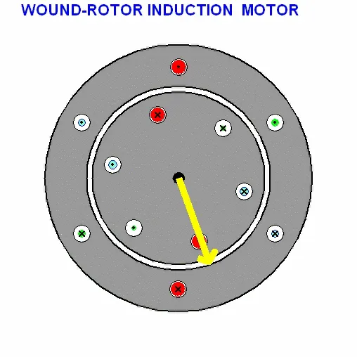
stator speed is Wms & rotor speed is Wmr then Slip (S) = [NS – Nr / Ns] where 0 < s < 1
Nr = (1 – S) * Ns
% Of slip = [NS – Nr / Ns] * 100
Clutch Operation –

In mechanical device that transfers all power from the source into the load of a vehicle. Without properly operating clutch power transfer and gear shifting will be the very difficult.
A clutch is located between engine flywheel and transmission. The first section of this system starts at the flywheel and flywheel is connected with pressure plate with clutch friction discs between two items, on the outside of pressure plate will be clutch control unit or the throughout bearing. The pressure plate assembly is secured to the flywheel via bolts connecting the cover stamping to the flywheel.
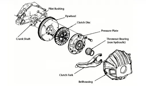
During the engagement the pressure plate assembly clamps the disc assembly against the flywheel, transmitting engine power to the transmission.
During disengagement, power flow is interrupted when the pressure plate no longer clamps the disc against the flywheel. Instead the pressure plate lifts away from the flywheel, creating a large gap which is enough for the disc to disengage from the flywheel.
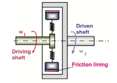
The clutch connects the driving shaft and the driven shaft each other and transfer equal amount of torque but they don’t spin in the same speed because of slip.
As we can see speed in both shaft is not same, Driving shaft speed = W1.
Driven shaft speed = W2.
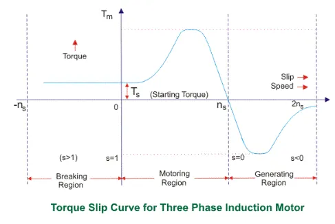
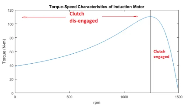
The torque slip curve for an induction motor gives us the information about the variation of torque with slip. The slip is defined as the ratio of difference of synchronous speed and actual rotor speed to the synchronous speed of the machine. The variation of the slip can be obtained with the variation of speed that is when speed varies with the slip will also vary and torque corresponding to that speed will also vary.
The torque speed characteristics can be divided roughly into 3 regions –
- Low slip region.
- Medium slip region.
- High slip region.
Motoring Mode –
In this mode of operation, supply is given to the stator sides and motor always rotates below the synchronous speed. The induction motor torque varies from zero to full load torque as the slip varies. The slip varies from zero to one. It is zero at no load and one at standstill. From the curve it is seen that the torque is directly proportional to the slip.
So more is the slip more will be the torque produced and vice versa. The linear relationship simplifies the calculation of motor parameter to great extent.
Generating Mode –
In this mode of operation induction motor runs above the synchronous speed and it should be driven by prime mover. The stator winding is connected to the three phase supply to which it supplies electrical energy. Actually, in this case, the torque and slip are both are negative so the motor receives mechanical energy and delivers electrical energy. Induction motor isn’t much used as generator because it requires reactive power for its operation.
Braking Mode –
In the braking mode the two leads or the polarity of the supply voltage is changed so that the motor starts to rotate in the reverse direction as a result the motor stops. This method of braking is known as plugging. This method is used when it is required to stop the motor within a very short period of time. The kinetic energy is stored in the revolving load is dissipating as heat. Also motor is still receiving the power from stator which is also dissipated as heat. So as a result of which motor develops enormous heat energy. For this stator is disconnected from the supply before motor enters the braking mode.
W = Ws (1 –S)
W = Rotor speed.
Ws = Stator Synchronous Speed.
S = Slip.
2) Starting time Induction Motor Drive
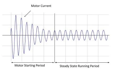
The duration of time when a large current, which flows during the starting of an Induction Motor. Normally, the starting current of an Induction Motor is 6 to 8 times of full load current.
The time from starting torque point to maximum or peak torque point after which motor is engaging with load is called as starting time
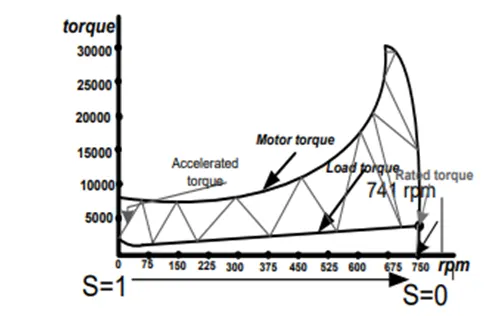
Large motor over current protection is normally set to trip prior to locked rotor withstand time (LRWT) provided by the motor manufacturer, after the calculation motor start time is determined by the motor designer based on the heating f the rotor parts for locked rotor condition, where motor continuously requires large value of inrush current.
At the time of starting, induction motor drives high values of current (Motor is a constant impedance device during the starting condition) that are very closed to the motor’s locked rotor value & remains at this value for the time required to start the motor.
The capability to calculate motor starting time for large induction motor is important in order to evaluate the relative strength of the power system.
Parameters given –
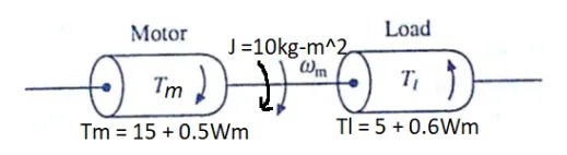
Moment of inertia of motor and combined load system (J) = 10 Kg – m2.
Motor torque (Tm) = 15 + 0.5 Wm.
Torque (TI) = 5 + 0.6 Wm.
A motor generally drives the load or machine with some transmission system. while the motor always rotates, a load may rotate or may undergo translational motion.
Motor torque or load torque relation is defined as ,
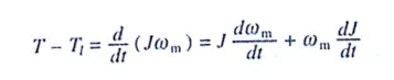
for drives with constant inertia (dJ / dt) = 0
therefore,
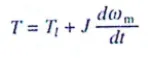
Motor torque is counter balanced by Load torque and dynamic torque.
Dynamic torque component is present only during transient operations like sudden change in the system during braking, Acceleration / Deceleration of the motor.
At equilibrium steady state, T = TI
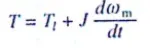
Where,  is the synchronous speed of the motor
T = TI
15 + 0.5 Wm = 5 + 0.6 Wm.
15 – 5 = 0.6 Wm – 0.5 Wm
0.1 Wm = 10
W(m) = 100 rad / sec…………Steady State Speed
Therefore,
15 + 0.5 Wm = 5 + 0.6 Wm. (dWm / dt)
(dWm / dt) = (10 – 0.1 Wm) / 10
1 – 0.01 Wm
dt = (1 / 1 – 0.01Wm) d Wm
integrating the above equation w.r.t. time (t)
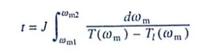
The integral limits should be considered from initial condition of the motor to the end of transit state after which the motor attains its steady speed. So we consider steady speed. So we consider Wm1 = 0 & Wm2 = 95% of Wm.
W(m) = 100 rad / sec.
Wm1 = 0 rad / sec.
Wm2 = 95 rad / sec.
Therefore,
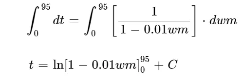
At initial condition, when t = 0, Wm = 0
C = 0
Applying integral limits,
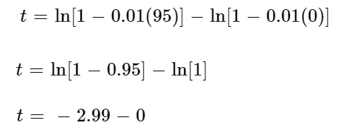
Therefore, starting time for given Induction Motor is t = 3s.
3) Stability & Equilibrium points of Induction Motor Drive –
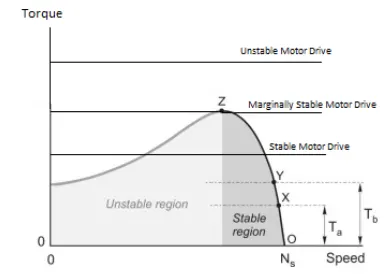
Stability of the motor can be defined as capacity of the motor to drive the load. If the motor has enough power and is able to drive a load, then it is called as a stable motor drive.
For a motor to be stable,
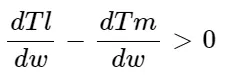
The difference of the change in the load torque with respect to the speed change with that of change in motor torque should be always greater than zero (0) for a motor to be stable.
Given data,
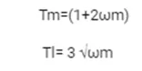
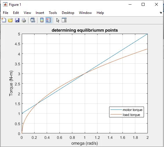
At steady state,
Tm = TI
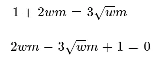
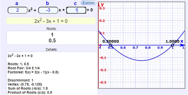
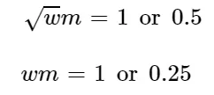
The above quadratic equation can be solved where, root = sqrt(Wm)
A =2
B = -3
C = 1
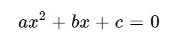
Therefore,
Also,
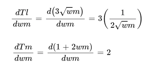
Therefore, steady state equation becomes,
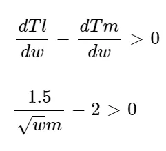
Substituting the values of Wm,
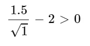
-0.5 > 0, False
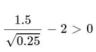
1 > 0, True
Therefore, Wm = 0.25 Rad / sec.
Equilibrium point is achieved at 0.25 Rad. / Sec.
1.
clear all
close all
clc
w = linspace (0,150)
Tm = 15 + (0.5 *(w));
T1 = 5 + (0.6*(w));
plot(w,Tm)
title('determinig  equilibrium points');
xlabel('omega(rad/s)')
ylabel('torque (N-m)')
hold on
plot(w, T1)
legend('motor torque', 'load torque');
legend('location', 'best')
grid on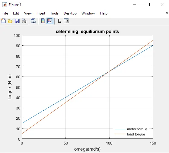
2.
clear all
close all
clc
t_p = [0 300];
i_c = [0 0];
[t w] = ode45(@functionomega, t_p, i_c);
plot (t,w)
title('w-dot (dw/ dt)');
xlabel('time(sec)');
ylabel('omega (rad /sec)');
grid on
function [w_dot] = functionomega(t,w)
w_dot = 1-0.01*(w);
end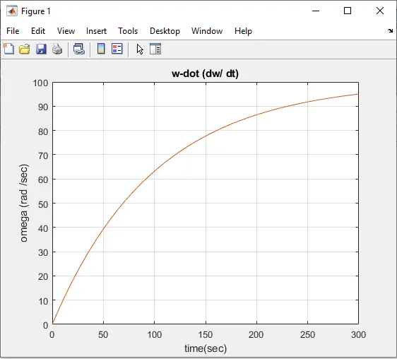
3.
clear all
close all
clc
w = linspace(0,2);
Tm = 1 + (2*w);
T1 = 3*sqrt(w);
plot(w,Tm)
title('determining equilibriumm points')
xlabel('omega (rad/s)');
ylabel('Torque (N-m)');
hold on
plot(w, T1);
legend ('motor torque' , 'load torque');
legend('location', 'best')
grid on