Induction Motor Characteristics
OBJECTIVE
- Discuss the equivalent circuit network of the induction motor MATLAB model.
- 3 phase, 50 Hz induction motor, represented by equivalent circuit constants X1 = X2 = 0.1 ohm and R1 = R2 = 0.2 ohm is operated at half of rated voltage and frequency. Calculate the ratio of starting torque at half voltage & frequency to rated values.
- Make a MATLAB script file that will plot speed-torque characteristics for the frequency control method.
- Explain in brief about the operation of BLDC motor.
Solution 1:
Equivalent Circuit of Induction motor :
The Equivalent Circuit of an Induction motor enables the performance characteristics which are evaluated for steady-state conditions. An induction motor is based on the principle of induction of voltages and currents. The voltage and currents are induced in the rotor circuit from the stator circuit for the operation. The equivalent circuit of an induction motor is similar to that of the transformer.
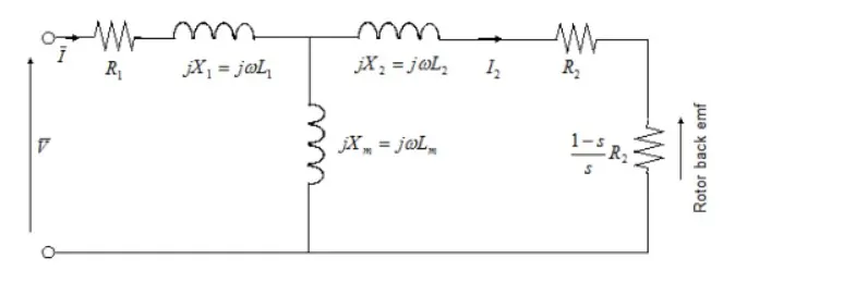
Induction motor model design can be done any of the following way:
Simplified Induction Motor :
The Simplified Induction Motor block represents the electrical and torque characteristics of an induction motor powered by an ideal AC supply. This block is available in the Simscape library.
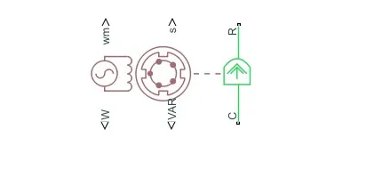
-
The block does not model the starting mechanism for a single-phase induction motor.
-
When you parameterize the block by motor ratings, the block derives the equivalent circuit model parameters by assuming that the effect of the magnetizing inductance Lm is negligible, and the magnetizing inductance is not included in the simulated component.
The output of this model are:
- Real Power
- Mechanical Speed
- Imaginary Power
- Motor Slip
Induction Motor :
The Induction Motor block implements a three-phase induction motor. The block uses the three-phase input voltages to regulate the individual phase currents, allowing control of the motor torque or speed.
This block is present in Powertrain Blockset.
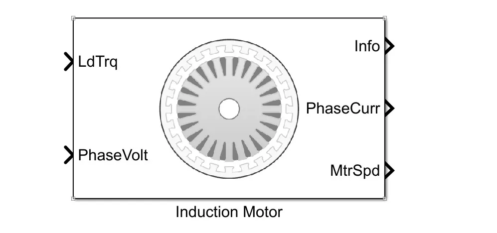
By default, the block sets the Simulation Type parameter to Continous use a continuous sample time during the simulation. If you want to generate code for fixed-step double- and single-precision targets, considering setting the parameter to Discrete. Then specify a Sample Time, Ts parameter.
The Output of this block are :
- Phase Current
- Motor Torque
- Motor Speed
Solution 2:
Data Given,
Number of Phases = 3
Rated Frequency, f = 50 Hz
Stator Inductance,`X_1 = 0.1 ohms`
Rotor Inductance,`X_2 = 0.1 ohms`
Stator Resistance,`R_1 = 0.2 ohms`
Rotor Resistance,`R_2 = 0.2 ohms`
Starting torque of the induction motor is calculated by,
`T = [frac{3}{omega_(ms)}*frac{V^2*frac{R_2}{s}}{(R_1 + frac{R_2}{s})^2 +(X_1 + X_2)^2 }]`
where,`omega_ms` is synchronous speed, X and R represent inductance and resistance of stator and rotor and s is slip of motor.
For our problem, since we are only interested in starting torque, we can eliminate the slip term from our equation, because the motor speed will be zero at the beginning so slip will be one.
Problem Description
Since our problem involves the calculation of torque at the operation of rated voltage and frequency and half of rated voltage and frequency.
Changing voltage or frequency will not affect the resistance and inductance of the motor as it is a fixed value provided by the operator. It will only affect synchronous speed and voltage in the equation.
Synchronous Speed calculation for Rated frequency,`f = 50 Hz`:
`omega_(ms1) = frac{120*f}{P} = frac{120*50}{P}`
`omega_(ms1) = frac{6000}{P} .......................(i)`
Synchronous Speed calculation for half Rated frequency,`f = frac{50}{2} = 25 Hz`
`omega_(ms2) = frac{120*25}{P}`
`omega_(ms2) = frac{3000}{P} .....................(ii)`
From the above two equation we can see that ,`omega_(ms1)` is half of `omega_(ms2)` which is at rated frequency.
So for half rated frequency, it can be written as `omega_(ms2) = frac{omega_(ms_1)}{2}`
Torque calculation for Rated Frequency
`T = [frac{3}{omega_(ms_1)}*frac{V^2*0.2}{(0.2 + 0.2)^2 +(0.1 + 0.1)^2 }]`
`T_(s1) = [frac{3*V^2}{omega_(ms1) }]` ..........................................(iii)
Torque calculation for Half Frequency
`T_(s2) = [frac{3}{omega_(ms_1)/2}*frac{(V/2)^2*0.2}{(0.2 + 0.2)^2 +(0.1 + 0.1)^2 }]`
`T_(s2) = [frac{6}{omega_(ms_1)}*frac{(V/2)^2*0.2}{(0.4)^2 +(0.2)^2 }]`
`T_(s2) = [frac{6}{omega_(ms_1)}*frac{(V/2)^2*0.2}{0.16 +0.04 }]`
`T_(s2) = frac{1.5*V^2}{omega_(ms1)}` ............................................(iv)
The ratio of starting torque at half voltage & frequency to rated values
`frac{T_(s2)}{T_(s1)} =frac{frac{1.5*V^2}{omega_(ms1)}}{frac{3*V^2}{omega_(ms1) }}`
`frac{T_(s2)}{T_(s1)}frac{1.5*V^2}{omega_(ms1)}* frac{omega_(ms1)}{3*V^2}`
`frac{T_(s2)}{T_(s1)} = frac{1}{2}`
Therefore the ratio of starting torque at half rated condition to rated condition is 0.5 or 1/2.
Solution 3:
MATLAB CODE
clc
clearvars


p = 3                      % no. of poles
s = linspace(0,1,50)        %slip values
s(1) = 0.001
f = linspace(20,60,50)       % frequency
r1 = 0.641                 % stator resistance
r2 = 0.332               % rotor resistance
x1 = 1.106                % stator resistance
x2 = 0.464                % rotor resistance
xm = 26.3                % magnetization branch reactance
wms = (120*f)/p           % synchronous speed

v_phase = 460/ sqrt(3);     % phase voltage
% Thevenin's equivalent voltage
v_th = v_phase * ( xm / sqrt(r1^2 + (x1 + xm)^2) );

z_th = ((j*xm) * (r1 + j*x1)) / (r1 + j*(x1 + xm));
r_th = real(z_th);
x_th = imag(z_th);

            % motor speed
for ii = 1:50
    for j = 1:50
       wm(ii,j) = (1-s(j))*wms(ii);
       t_ind2(ii,j) = (3 * v_th^2 * (2*r2) / s(j)) / ...
            (wms(ii) * ((r_th + (2*r2)/s(j))^2 + (x_th + x2)^2) );
    end
end
%wm = wm'

Plot

i = 1
cmap = jet(50);
while i<50
    plot(wm(i,:),t_ind2(i,:),'Color',cmap(i, :),'LineWidth',2.0);
    hold on
    % creating array for legend
    g(i) = [f(i)]
    i = i+5
end

grid on
grid minor
title("Torque Speed Characteristics with frequency Control")
xlabel("Motor Speed ,rad/sec")
ylabel("Torque,N-m")
% conversion of number to string for legend
g = num2str(nonzeros(g))
 g = g+"Hz"
legend(g)
%%.............................................................%%
RESULT
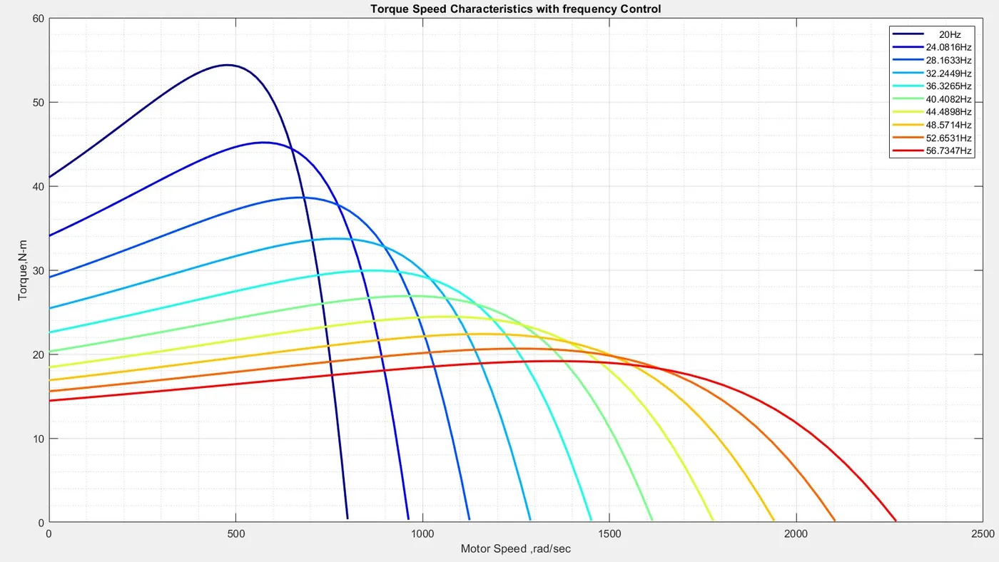
- From the above graph, we can see that by changing the frequency torque vs motor speed characteristics changes.
- We can see that as the frequency of the induction motor increases, the torque of motor decreases but motor speed increases.
- Changes in frequency affect the motor speed and synchronous speed of the motor.
Solution 4:
Brushless DC Motor :
A brushless DC motor ( BLDC motor) is an electronically commuted DC motor which does not have brushes. The controller provides pulses of current to the motor windings which control the speed and torque of the synchronous motor.
Construction :
Basically, a BLDC motor can be constructed in two ways- by placing the rotor outside the core and the windings in the core and another by placing the windings outside the core. In the former arrangement, the rotor magnets act as an insulator and reduce the rate of heat dissipation from the motor and operate at low current. It is typically used in fans. In the latter arrangement, the motor dissipates more heat, thus causing an increase in its torque. It is used in hard disk drives.
The Brushless DC motor consists of :
Stator :
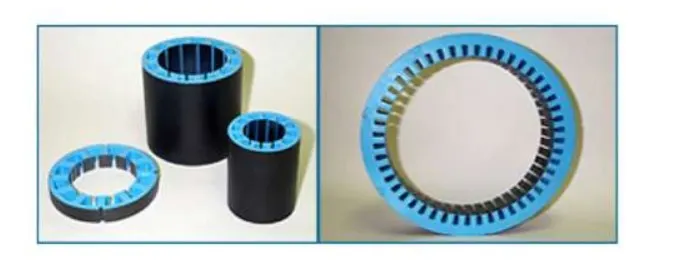
Similar to an Induction AC motor, the BLDC motor stator is made out of laminated steel stacked up to carry the windings. Windings in a stator can be arranged in two patterns; i.e. a star pattern (Y) or delta pattern (∆). The major difference between the two patterns is that the Y pattern gives high torque at low RPM and the ∆ pattern gives low torque at low RPM.
Steel laminations in the stator can be slotted or slotless as shown in Figure 2. A slotless core has lower inductance, thus it can run at very high speeds. Because of the absence of teeth in the lamination stack, requirements for the cogging torque also go down, thus making them an ideal fit for low speeds.
Rotor :
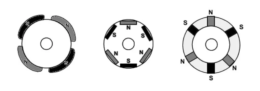
The rotor part of the BLDC Motor is made up of permanent magnets (usually, rare earth alloy magnets like Neodymium (Nd), Samarium Cobalt (SmCo), and alloy of Neodymium, Ferrite, and Boron (NdFeB)).
Based on the application, the number of poles can vary between two and eight with North (N) and South (S) poles placed alternately. The following image shows three different arrangements of the poles. In the first case, the magnets are placed on the outer periphery of the rotor.
Working:
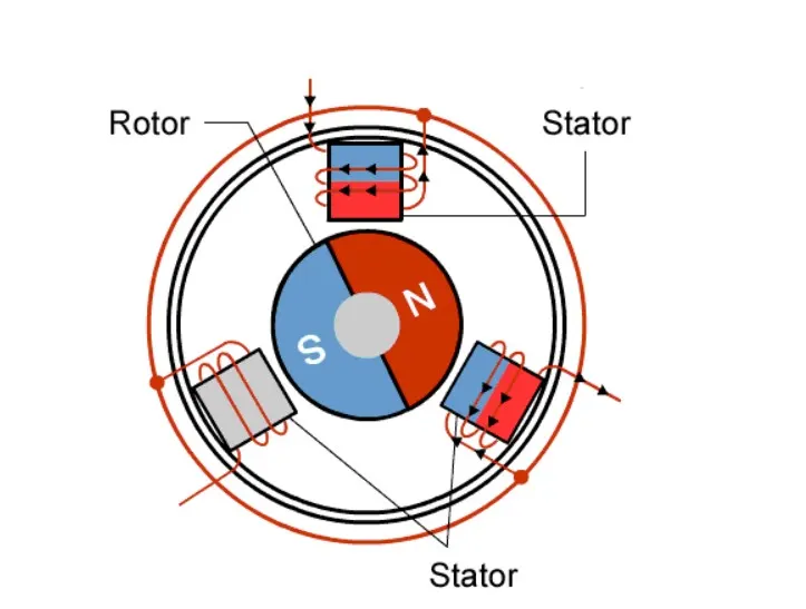
The principles for the working of BLDC motors are the same as for a brushed DC motor, i.e., the internal shaft position feedback. In the case of a brushed DC motor, feedback is implemented using a mechanical commutator and brushes. Within the BLDC motor, it is achieved using multiple feedback sensors. In BLDC motors we mostly use a Hall-effect sensor, whenever rotor magnetic poles pass near the hall sensor, they generate a HIGH or LOW-level signal, which can be used to determine the position of the shaft. If the direction of the magnetic field is reversed, the voltage developed will reverse too.
The control unit is implemented by microelectronic has several high-tech choices. This may be implemented using a micro-controller, a dedicated micro-controller, a hard-wired microelectronic unit, a PLC, or similar another unit.
The Analog controller is still using, but the can not process feedback messages and control accordingly. With this type of control circuits, it is possible to implement high-performance control algorithms, such as vector control, field-oriented control, high-speed control all of which are related to the electromagnetic state of the motor.
Besides all these, we find high-performance PIC (Power Integrated Circuit), ASIC (Application Specific Integrated Circuits) …etc. that can greatly simplify the construction of the control and the power electronic unit both.
PWM (Pulse Width Modulation) wave can be used to control the speed of the motor. Here the average voltage is given or the average current flowing through the motor will change depending on the ON and OFF time of the pulses controlling the speed of the motor.
Advantages
- Brushless motors are more efficient as its velocity is determined by the frequency at which current is supplied, not the voltage.
- As brushes are absent, the mechanical energy loss due to friction is less which enhanced efficiency.
- BLDC motor can operate at high-speed under any condition.
- There is no sparking and much less noise during operation.
- More electromagnets could be used on the stator for more precise control.
- BLDC motors accelerate and decelerate easily as they are having low rotor inertia.
- It is a high-performance motor that provides large torque per cubic inch over a vast speed range.
Conclusion
- The given challenges have been successfully performed.
- By changing the frequency of the induction motor, we can see there's is a change in the speed-torque relationship of the motor.
- Brushless motor operation and working have been successfully noted down.
References
1. https://www.edn.com/brushless-dc-motors-part-i-construction-and-operating-principles/
2.https://www.electrical4u.com/speed-control-of-three-phase-induction-motor/