Identification of Cracks
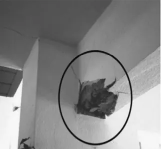
Question-1. (a) What is the mode of failure or damage of the beams in the figure above? Are the damages repairable? Elaborate
Answer)
Observation:
- Cracks are large and concrete spalled.
- Reinforcements are visible through the crack.
- Cracks are found at support bottom.
- Cracks developing from the bottom of the beam towards top.
- No cracks found in top of the beam.
- No cracks fopund in Column.
- Cracks also trying to form below the adjacent connected beam.
Discussion:
- As the cracks are formed in the bottom of the beam at support zone which is clearly compression zone under
gravity condition. But the cracks are formed only at the bottom towards top @ support which means due to
seismic/lateral forces reversal of moment and stress occurs at the Support bottom. - At that moment, the support bottom of the beam becomes ductile and provided reinforcement's moment
capacity which does not satisfies the requirement moment capacity. - In other words, ductile reinforcement not provided or not detailed well for under taking the reversal stresses due to lateral forces.
- In top of the beam no cracks are formed due to the top flange of the beam (T-action of beam-slab)
Conclusion:
Mode of failure:
It is a form of flexural failure due to the Reversal of stress due to the earthquake.
Since the provided reinforcement is not enough and got yielded which leads to concrete spalling which is not repairable by simple manner.
Retrofitting: Requires modern retrofitting techniques to strengthen beam using external concrete jacketing and steel platting techniques are used.
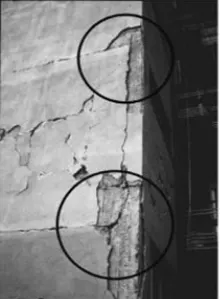
Question-1. (b) What is the mode of failure or damage of the beams in the figure above? Are the damages repairable? Elaborate
Answer)
Observation:
- As per the view in the photo it seems that the cracks are at the beam column edge.
- Cracks are formed along the beam on top and bottom parallel to beam.
- It Looks like beams totally separated from the column joint
- Other than that, no cracks are developed diagonally.
- Concerte is not Severely Crushed.
Discussion:
- As the cracks are only parallel to the beam direction it is clearly shows that it is the lateral displacement of the beam from the column connection. Which is due to the insufficient anchorage length of the reinforcement bar in the beam.
- This insufficient anchorage length of reinforcement and poor detailing of the beam in connection location leads to the pull-out mechanism of the beam from the column connection.
- Provided anchorage of reinforcement does not satisfy the lateral moments occurred.
Conclusion:
Mode of failure: In SufficientAnchorage failure/ Pull-out failure.
As the beam is pulled out due to insufficient developing length and beam is disconnected from the column it is not repairable.
Retrofitting: Strengthening should be done by providing brackets in the column to support the beam and to eliminate future crack developing in the beam column edge.
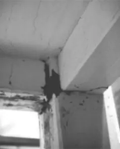
Question-1. (c) What is the mode of failure or damage of the beams in the figure above? Are the damages repairable? Elaborate
Answer)
Observation:
- Cracks are formed exactely at the joint of the beam and column
- Cracks in beam developed through its entire Width.
- In both intersecting beams cracks formed in the CS direction of the beam.
- And also, cracks are developed in the slab in the direction similar to beam cracks.
- Randon Cracks Developed in slab also.
Discussion:
- Since the observed cracks only in the beam and slab junctions which all cracks are in similar direction
- and also the cracks extended throughout the beam width it clearly shows it is due to the plastic hinge formation at the junction.
- And also, in both directions no infilled walls are present, therefore this floor shown in picture is more possibly to be ground floor or floors without walls which have high possibility to be soft storey.
- Combining these all possibilities the occurrence of plastic hinge is possible and the failure caused due the plastic hinge failure.
Conclusion:
Mode of failure: It is Plastic Hinge failure
Retrofitting: The join can be strengthened. Since the cracks are minor it is easily repairable by providing special connection steel plates for beam and column.
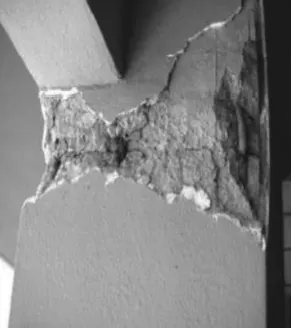
Question-2. (a)
Answer)
Observation:
- Cracks and concrete Damage shown at the top of the column.
- Concrete Damage all around the Column face.
- Beam are safe.
- Crack occur in the beam column junction location.
- By referring the view of the picture, it clear shows no infilled walls present and also have possibility that it is Ground floor or a parking zone.
- It is a external Column for sure.
Discussion:
- It is soft storey Failure
- Top of the column spalling of concrete occurred at beam-column junction. As per the observation no reinforcement bucking was happened.
- No infilled walls and crack occurred at the top therefore more possibility of plastic hinge formation.
- This plastic hinge formation results in the spalling of concrete.
Conclusion:
Mode of failure: It is Plastic hinge failure.
Retrofitting: No simple method of repair is possible, column bracketing and connection plates are provided for further controlling of crack development and strengthening for stability of structure.
Question- 2.( b)
Answer)
Observation:
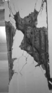
- Concrete developed complete breakage diagonally.
- Cracks are formed in the column mid of the column height.
- Cracks are larger and spalling of concrete occurred and reinforcement provided are clearly visible.
- No deformation occurred in the reinforcement provided.
- reinforcement Links provided are very wider as shown in picture.
Discussion:
- By observing the pictures, we can assume that the cracks are formed in the mid of column.
- No buckling of column main reinforcement occurred since we can understand this crack is not due to the axial forces.
- And the shear links are wider in space which clearly leads to the inadequacy to counteract the shear stress of the column, which cause the cracks and concrete spalling.
Conclusion:
Mode of failure: pure Shear failure. Since it is pure shear failure clearly due to the inadequate links provided it is not repairable by simple means.
Retrofitting: Need to retrofit the column section by using composite structures like external column jacketing using steel plates and shear plates are provided or any other composite techniques should be followed.
Question -2. (c)
Answer)
Observation:
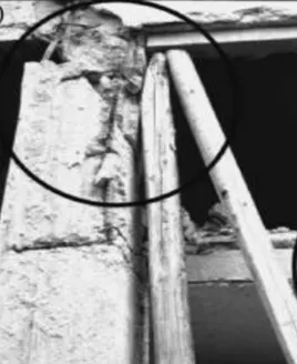
- As shown in the picture Column completely failed.
- Failure are at the top of Column.
- Beams are standing only due the external temporary support provided.
- Another mid-level slab is resting in the column.
- No infilled walls are there and also seems to be external column.
- Bamboo is given for Temporary Support.
Discussion:
- The Mid-level slab resting in the column in between the effective length of the column which provide stiffness at the intersection zone
- And made the column acts as short column which absorbs more stiffens and axial force all around.
- For that condition the columns are not designed which results in column failure.
- The wooden piles might be post failure Supporting after column failed , providing temporary prop to avoid collapse of the entire Structure.
Conclusion:
Mode of failure: Short column failure. Total column failed due to the short column failure effect. Since it is not repairable.
Retrofitting: We have to introduce steel props for temporary supporting of the column to prevent complete failure of the structure.
Column jacketing should be suggested for strengthening of the structure.