Hyperworks basic
Aim
To understand basics of Hyperworks and meshing
To use the meshing and Geometry cleanup tools
To implement the learnt tools while working on models
Objective
1. Using the given 2D Drawing create a simple bracket in HyperWorks.
2. Element size: Min.Length=2mm, Target length=5mm, Max.Length=8mm
3. From the given FE model extract the CAD surface.
1. Given 2D Drawing
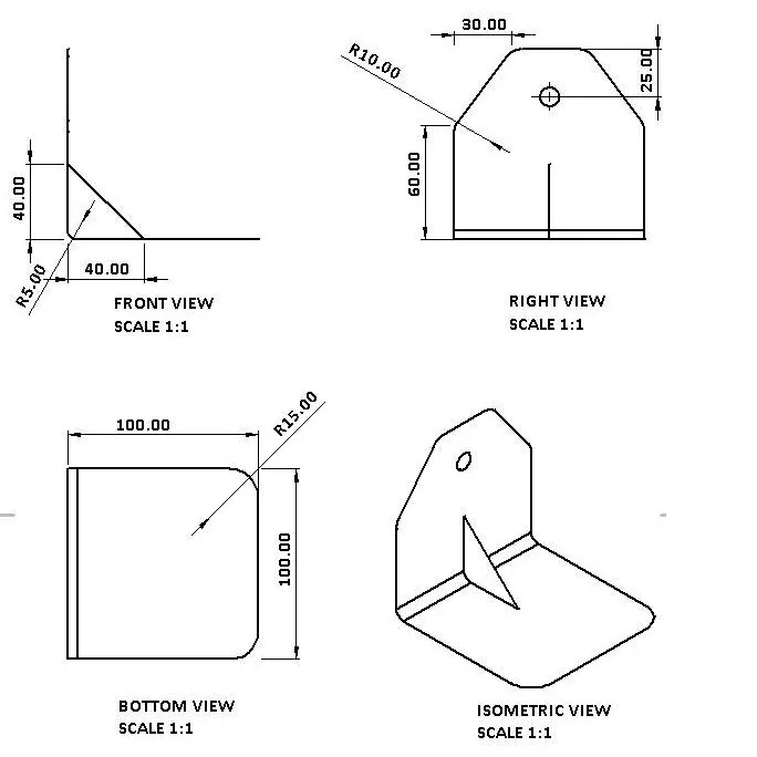
Creating 4 nodes in the co-ordinate system
Go to Nodes select  give co-ordinate values and create
Step 1
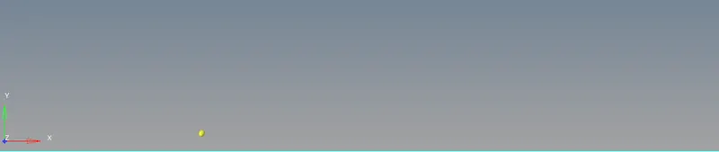

Step 2


Step 3
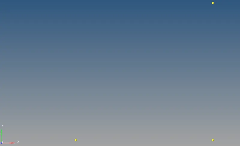

Step 4


Go to Lines select  join the nodes by selecting Linear Nodes
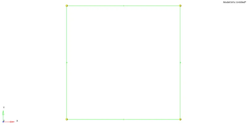

Go to Tools -> Translate

Select nodes to be translated and give magnitude value
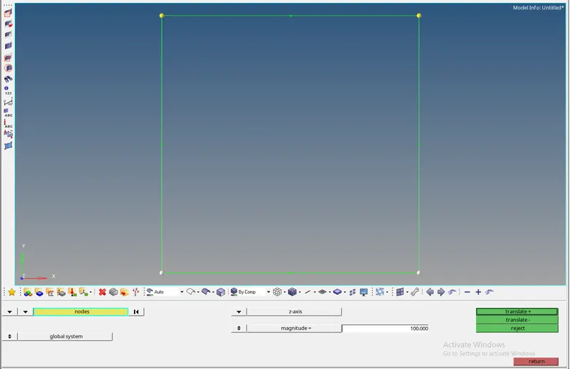
Click on nodes and duplicate them and with respect to axis click translate +/-
Press F4 and check distance between nodes
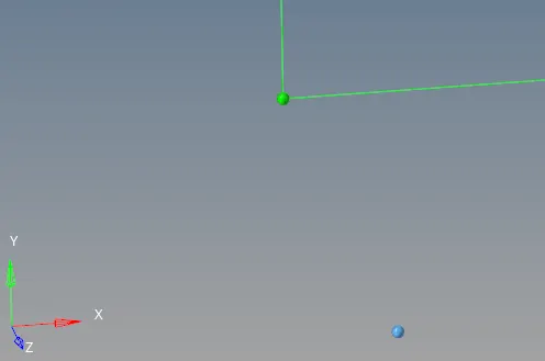

Join the nodes using linear nodes
after joining
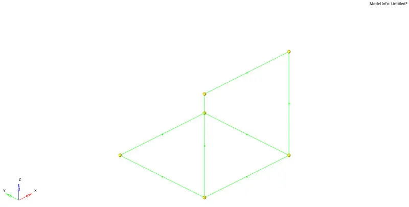
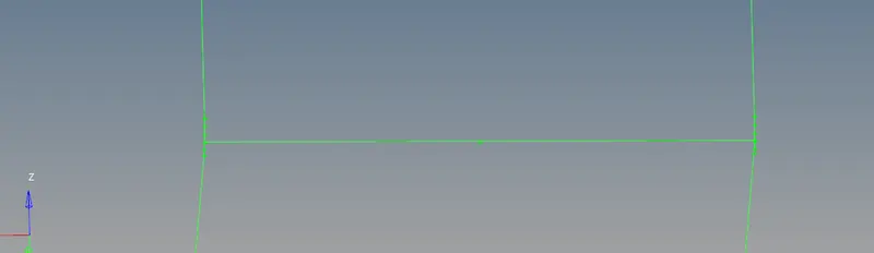
Create fillet of 5mm

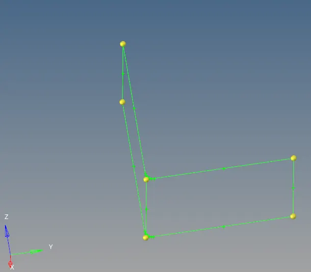
Clear nodes - Go to Temp nodes > select the nodes and clear

After creating fillet delete the line in mid
Surface Creation
Go to Surfaces -> select ruled 
Pick one end and click on mouse middle button and pick other end and click on mouse middle button -> Surface will be created
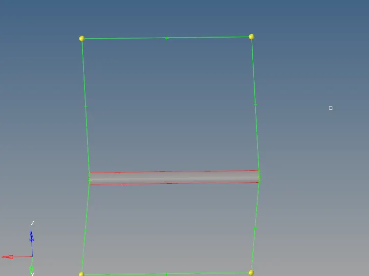
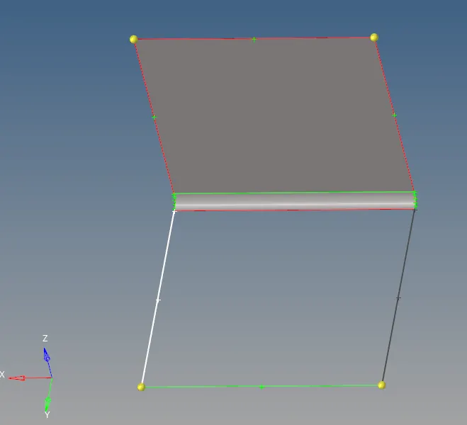
Create a fillet of 15mm on lower side
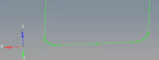
Create Surface
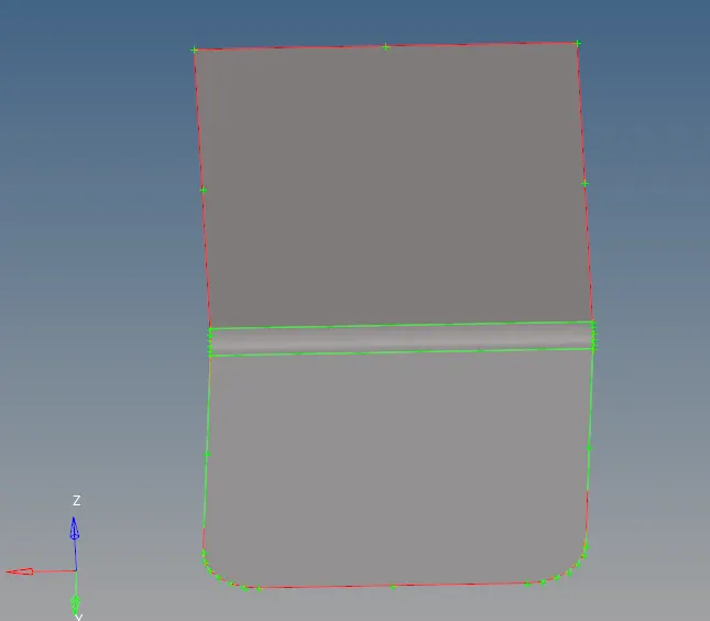
Create nodes and a mid node using  Interpolate nodes
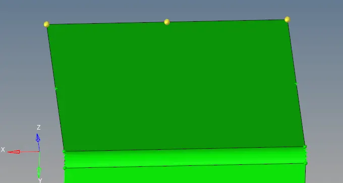
Translate the mid node to 30mm below where hole need to be created
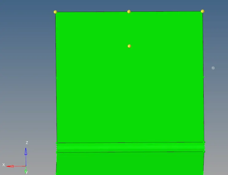
Create Circle using circle with radius in Line option
radius = 5mm with screen normal

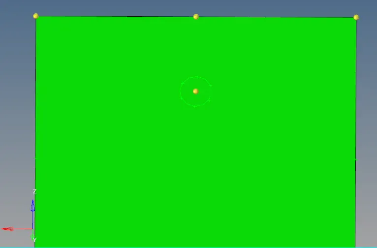
Go to Surface edit -> Trim with lines and normal to surface

Delete the trimmed surface
Hole is created with 5mm radius
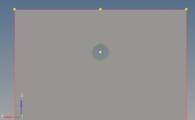
Create two nodes in the base
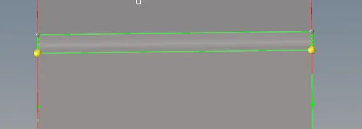
Translate and rotate to 60mm
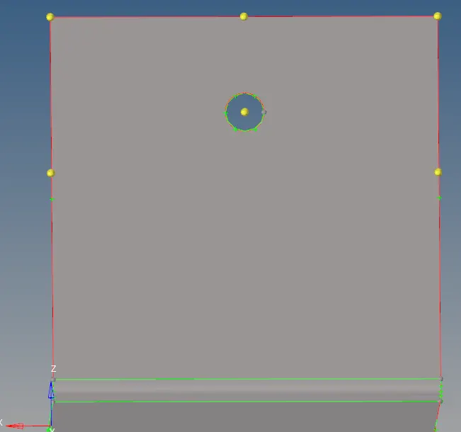
Create two nodes with 30mm distance
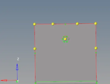
Join nodes diagonally with above nodes
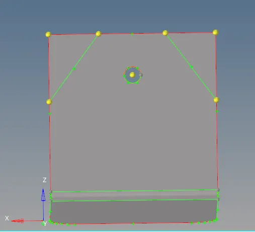
Trim the lines with respect to surface and delete
after deleting unwanted lines join the lines
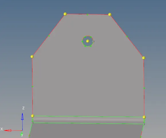
Create nodes on base center to create rib

Go to ribs -> select N1 - base node N2 - N1 above node N3 is last node
Starting node and end node to be selected

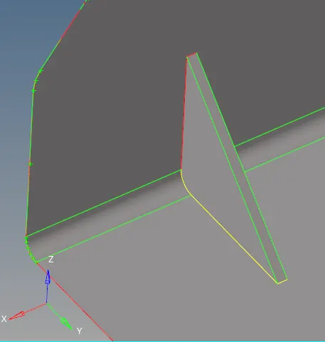
Delete unwanted lines and surfaces
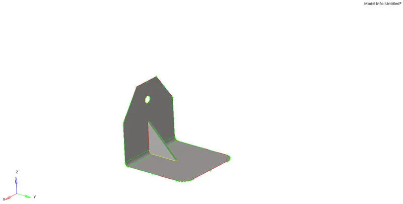
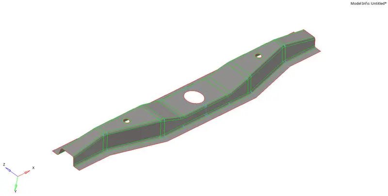
Geometry cleanup was done
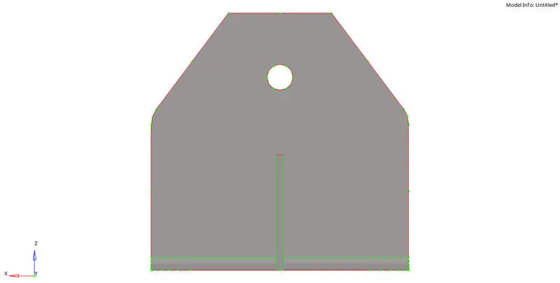
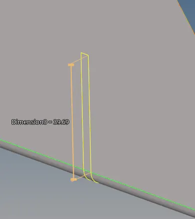
Rib dimension = 40mm diffference due to fillet
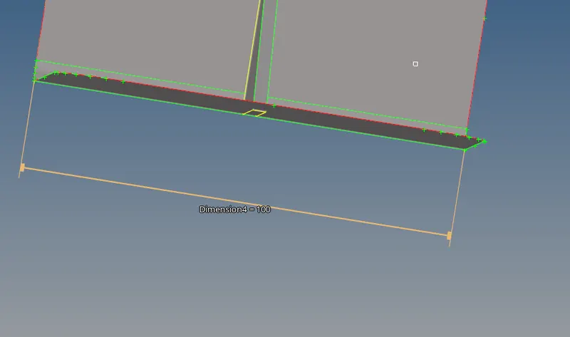
Base dimension = 100mm
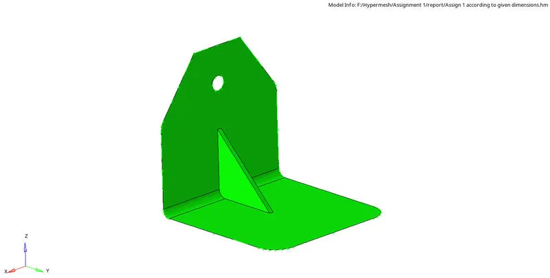
2. 2D Meshing
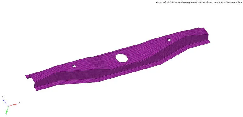
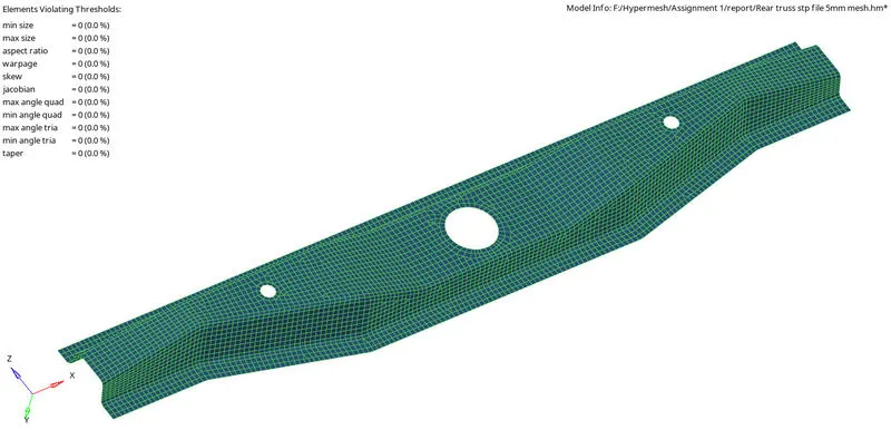
Element size: Min.Length=2mm, Target length=5mm, Max.Length=8mm
Given Stp model
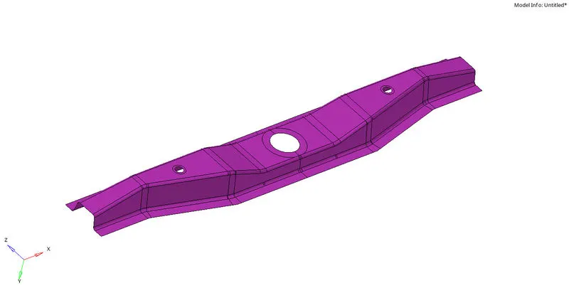
Geometry Cleanup
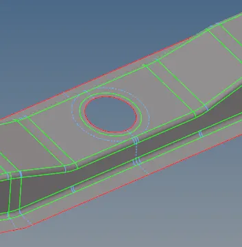
Washer slip of 5mm was created around the circle in mid
Meshing was done step bt step
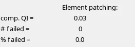
Minimum Length was found within limit


Maximum Length was found within limit


3.Extracting CAD surface from given FE model
Given Meshed FE (Side body) model
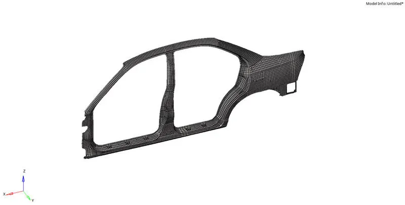
Go to Surfaces  from FE option
In Elements -> Select all elements and select create

FE to CAD Surface
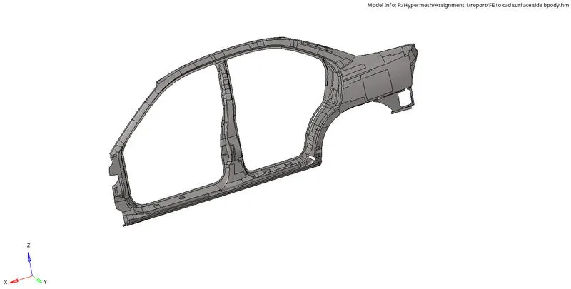
After extracting from FE some surfaces were not found
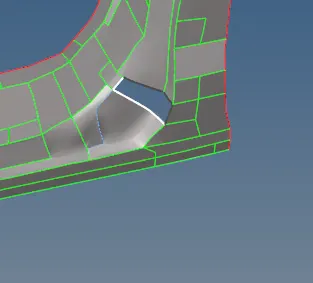
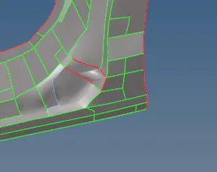
Surfaces were filled using  ruled tool in Surfaces

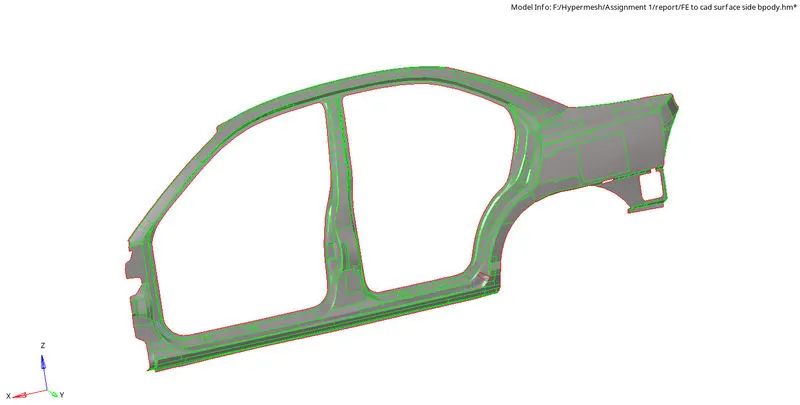
FE to CAD extracted surface (Side door)
Conclusion
1. Learnt to create CAD Surface of bracket using Hyperworks
2. Learnt to use meshing tools and performed 2D mesh on given model
3. Extracted Cad Surface from given FE model