Hood design-Week 2
HOOD ASSEMBLY DESIGN - BIW
OBJECTIVE -
To develop the hood inner and outer panels considering the safety, functionality and manufacturability, following the industrial standards.
ABSTRACT -
Body in white (BIW) is the stage in automobile manufacturing in which a car body's frame has been joined together, that is before painting and before the motor, chassis sub-assemblies, or trim (glass, door locks/handles, seats, upholstery, electronics, etc.) have been integrated into the structure. Assembly involves different techniques such as welding (spot, MIG/MAG), riveting, clinching, bonding and laser brazing. In car design, the "body in white" phase is where the final contours of the car body are worked out, in preparation for the ordering of the expensive production stamping die. Extensive computer simulations of crash-worthiness, manufacturability, and automotive aerodynamics are required before a clay model from the design studio can be converted into a body in white ready for production.
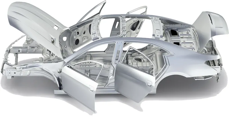
Body in white (BIW)
The hood (North American English) or bonnet (Commonwealth English) is the hinged cover over the engine of motor vehicles. Hoods can open to allow access to the engine compartment, or trunk (boot in Commonwealth English) on rear-engine and some mid-engine vehicles, for maintenance and repair. Hoods are typically made out of the same material as the rest of the body work. This may include steel, aluminium, fiberglass or carbon fibre. However, some aftermarket companies produce replacements for steel hoods in fiberglass or carbon fibre to make the vehicle lighter. Hood consists of an outer panel and an inner panel. The inner panel provides strength and support, where the outer panel is a metal cover which have styling factors.
HOOD-TYPES -
There are two major types of hoods;
- Inlaid hood
- Wrap around hood
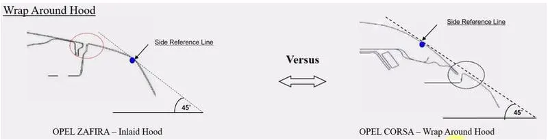
INLAID HOOD
It is lightest among all types of hoods. But it is easily subjected to border defects and body unevenness during manufacturing. Here I am designing an inlaid hood.

WRAP AROUND HOOD
As name itself it wrap around the car body. It can mask the geometrical defects and provide adequate stiffness. It is relatively safer than other types as it provides more safer areas for the pedestrian during impact.

DESIGN REQUIREMENTS & IMPORTANT REGULATIONS :
Head impact criteria for pedestrian safety -
The WHO reported most number of pedestrian lose their lives on 22% of all road accidents. Most pedestrian deaths occurs due to traumatic brain injury, resulting from the hard impact of the human head against the vehicle's stiff hood or windshield. Therefore, how to design a pedestrian-friendly vehicle and propose a new hood structure is a matter of urgency for minimizing pedestrian head injuries.
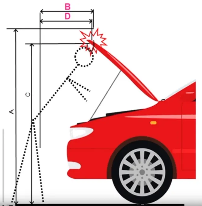
The EURO NCAP safety assessment program includes a test protocol for pedestrian protection. The protocol covers lower leg, upper leg, and head impact test as A, B, C and D in below figure. The figure also shows the schematic explanation of wrap around distance.
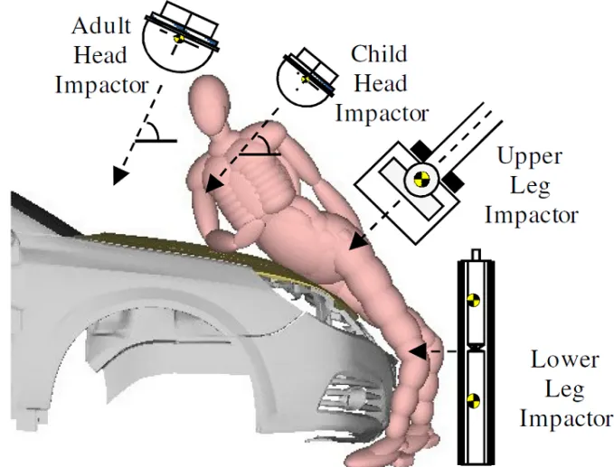
The head impact test assessment results mainly depend on the hood structure, whereas the leg impact tests results are highly influenced by components adjacent to the hood. Because the focus of these communications is on the hood design concept, the results presented in this study are limited to the head impact test results.
After an assessment test, the sample results are given as
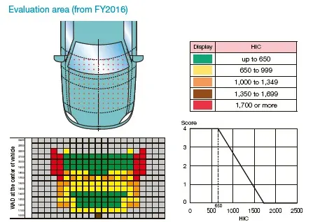
The impact received by the head impactors is measured and then evaluated using head injury criterion (HIC). The green zones that are shown in the graph are having less impact on pedestrian head than the red zones.
STATIC STIFFNESS -
Global car body stiffness is an important design attribute in vehicle design. Therefore, accurate characterization of this stiffness is needed.
Also, the force distribution while collision of front of car should and affect the passengers in the cabin. The design is in the way that the force is distributed towards the hinge points.
HEAD ZONE FOR LOCK STRICKER -
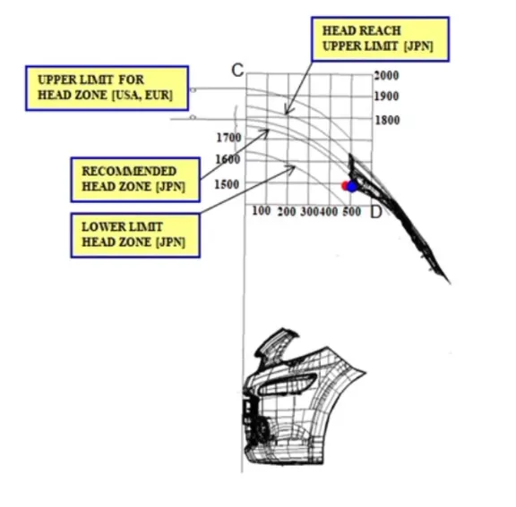
The opening of the hood should follow the circular trajectory, which circle is drawn from the mid-point of the line drawn between the both the hinge axis. In the opening condition of the hood, the head should touch the customer, means we have to design opening angle of the hood such that it does not interfere with the average height of the person in that particular region. The average height of the height of the person is varied from country to country.
OCCUPANT SAFETY -
Frontal crash collapse, maintain integrity with hinges and retention of loosed components, these are the three main considerations comes under occupant safety.
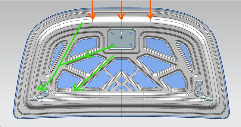
The design requirement of the car hood should also require to focus on the occupant safety as well. When a collision occurs, the force acts on the front side of the car is projected on mainly the hood. The force applied on the hood should not dissipate to the cabin, it required to force to be dissipated towards the vehicle frame. So the design of the hood is made in that way such that forces applied on it should be dissipated to the frame.
COMPONENTS OF HOOD ASSEMBLY -
The components are to be assembled are shown
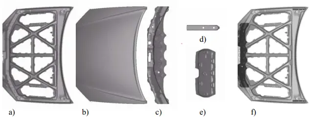
- Hood inner
- Hood outer
- Main reinforcement
- Hood hinge reinforcement
- Latch reinforcement
- Assembly without outer panel
Vehicle hood reinforcement structures are provided to reduce impact in collisions.
FUNCTIONAL REQUIREMENT -
functional requirements normally associated with closures such as passenger safety, air tightness, low cycle fatigue strength etc.
The design of the hood should meet the following functionalities :-
- Pedestrian safety - Child impact criterion, adult impact criterion and bonnet leading edge geometry.
- Vehicle quality - torsional stiffness, flutter resistance (bending stiffness), dent resistance, corrosion resistance, low mass, low mass weight distribution, low mass vehicle center of gravity and noise attenuation.
- Occupant safety - Frontal crash collapse, maintain integrity with hinges and retention of loosed components.
- Styling - Tight radii on hemmed panel edges, excellent painted surface quality, stretch flanges and good shape (low strain doubly curved surfaces)
- Manufacturing - Paint drain features, Dent resistance of outer panel during assembly, clean sheared edges of outer panel, no visual defects on the outer panel resulting from stretch forming and gauling resistance of inner panel
HOOD BALANCER & ITS FUNCTIONS -
The hood balancer of the car is the rod or gas stay which supports the hood in its opening position.
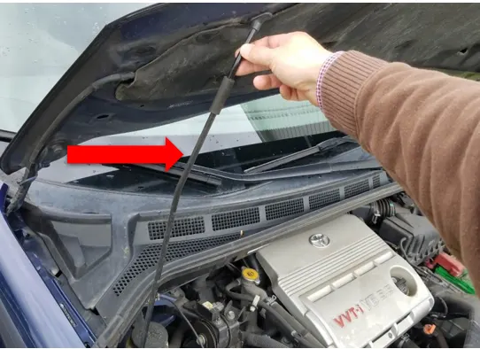
The above picture showing the image of the rod. The rod is not required to be strength, it should be given some curvature which improve the strength of the rod. As well as the maximum curvature should not exceed the 35 mm to reduce the bending of the rod.
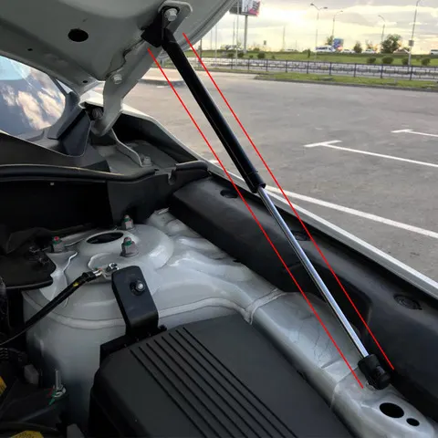
The above picture shows the gas stay, It has a gas spring consist of a precision rod attached to a piston, moving within a sealed cylinder containing pressurized nitrogen gas and oil.
HOOD HINGE & ITS FUNCTIONS -
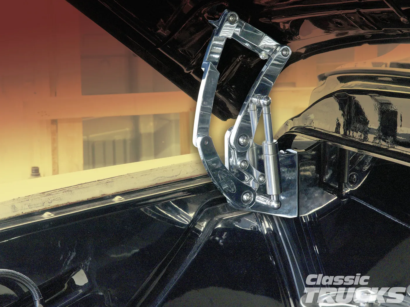
The hinge serves as a pivoting point for car hood panel which accommodate the opening and closing of it. Hinges are different types. The one end of the hinge is attached directly to the engine compartment of with the help of the flange and other side is attached to the inner panel of the hood. Two hinges are used on both ends of the hood, which their axeses are colinear.
HOOD LATCH & STRIKER -
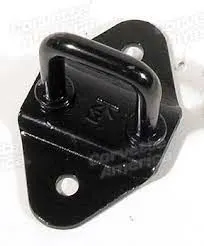
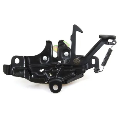
The latch and striker are the attachments which are used in the hood assembly to lock the hood in the closed postion. The below picture shows the striker and latch. The striker is attached to the hood panel whereas the latch is mounted on the front side of the engine compartment. The latch mechanism holds the striker in closed postion.
GAP & FLUSHNESS REQUIREMENTS -
The gap, gap parallel (equal distance between two gaps over a distance) and flush are the terminologies involved in automotive industry which influences the customer appeal. The gap and flush measurements of side closure are shown in the below picture.
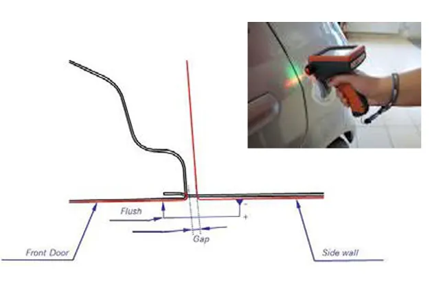
The gaps and flushes are given to the hood of the car with fender and sidewall by adjusting the hinge and striker during assembly.
In case of an automotive design, gap and leveling between the adjacent parts, known as gap and flushness, respectively, can be cited as examples of aesthetic dimensional requirements that influence customer's perception of quality.
MANUFACTURING OPERATIONS :
Forming operations (Deep drawing) :
It is sheet metal forming process, in which a sheet meatl blank is slightly clamped along it perimeter by a blank holder and radially drawn into a forming die by the mechanical action of a punch.
If the depth of the cup is more than half of its diameter, the process is termed as deep drawing.
The deep drawing is used to manufacture a product with seamless, complex shapes. This is tool related manufacturing process where the meatal is stretched or extended between two tool havles to create prospective shape.
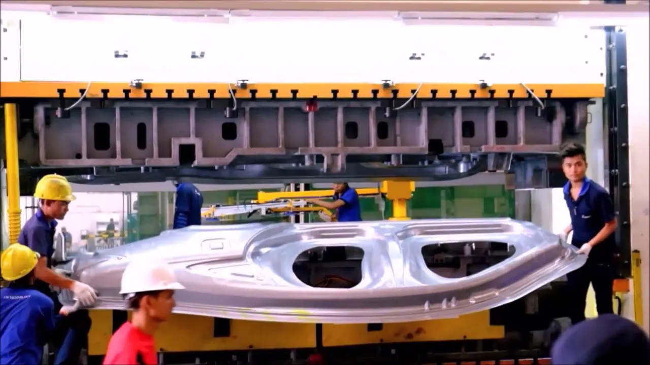
The figure shows the deep drawed panel.
EMBOSSING -
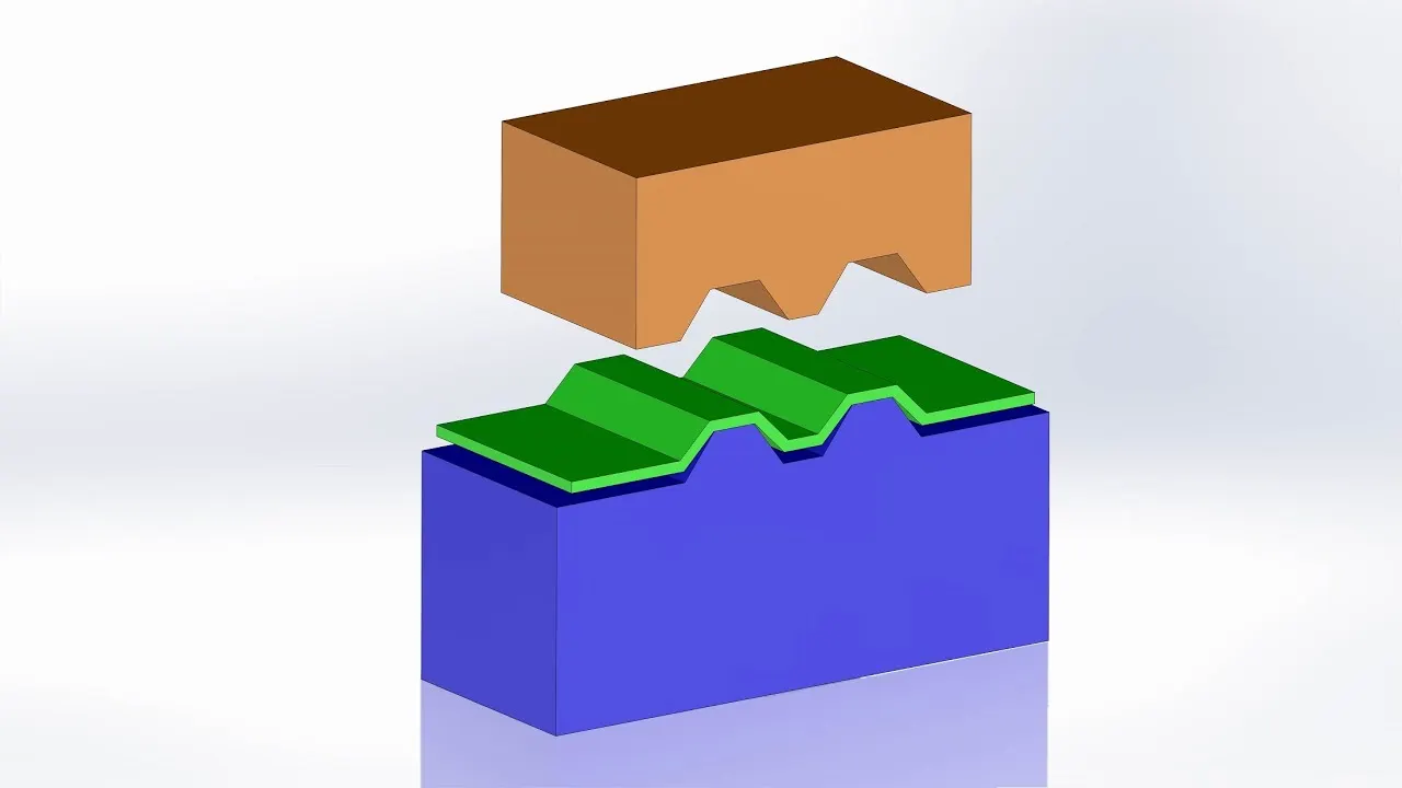
Embossing is the process of creating the raised portion in the sheet metal. Usually, the emboss is created by stamping process for producing raised or shrunken designs or relief in sheet metal.
BLANKING & PIERCIENG -
Blaking and piercing are the shearing processes in which a punch and die are used to produce parts from coil or sheet stock. The blaking produces the outside features of the component, while piercing produces internal holes or shapes.
JOINING OPERATIONS (HEMMING) -
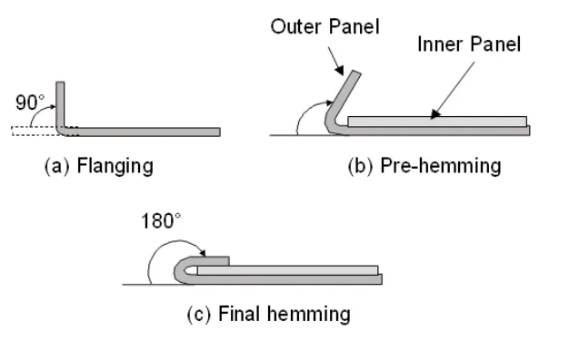
In automobile industry, the panels which are visible outside are joined with the inner panels or supports with the help of the hemming process. Hemming is comes into for outer panels because thermal joining processes leave the residual marks which are acceptable on the aesthetic surfaces.
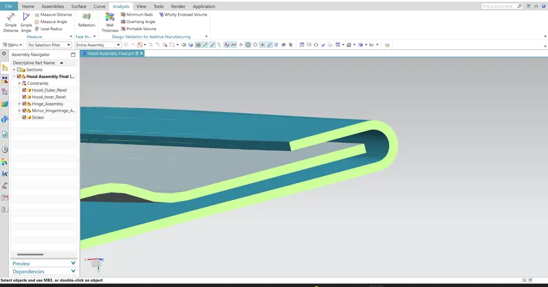
Hemming is the technology used in the automotive industry to join inner and outer closure panels together. It is the process of bending/folding the flange of the outer panel over the inner one. The accuracy of the operation affects significantly the appearance of the car's outer surfaces, and is therefore a critical factor in the final quality of a finished vehicle.
Hemming is performed in order to achieve a better final geometry in the vehicle's part and add resistance and rigidity to the part. Also, to allow a safe handling of the part.
TYPES OF HEMMING PROCCESS -
- Press hemming : Hemming presses are widely used in automotive manufacturing for hemming of sheet metal body components. The process uses traditional hydraulically operated stamping presses to hem closure parts and being the last forming process in stamping.
- Table-top hemming : Table top technology is based on an automatic system, which includes a set of electromechanical elements that make up the hemming machine. The system is valid both for steel and aluminum parts.
- Robot (roller hemming) : The robotized hemming systems use a standard industrial robot integrated with a roller hemming head, offering a very flexible solution. This roller hemming head consists of a body, some guides and a number of rolls that are designed according to the geometry of the part in each case. It is in principle a more simple and economic system than table-top hemming, offering a higher degree of flexibility. The roller hemming technology is valid both for parts made in steel and aluminum.
DESIGN METHODOLOGY :
Hood inner panel was designed at first. The various stages of inner panel development are shown below. Here, the embossings were created. The main design consideration is to diverge any impact forces away from the passenger cabin.
MASTER SECTION OF HOOD -
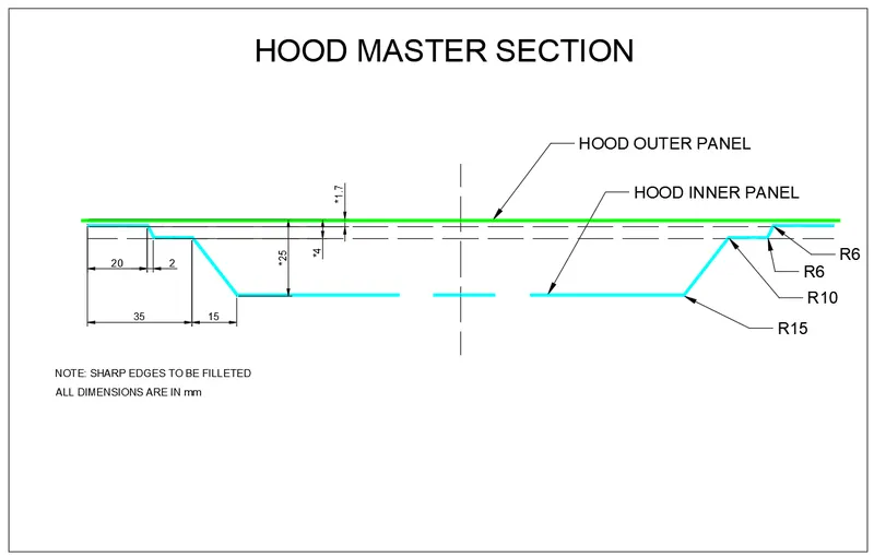
The master section of the hood inner panel is shown in the image below. It provides information such as distance between various layers (emboss), fillet radii, width, clearances etc.
STEP-WISE PROCEDURE -
Firstly, we worked in the assembly workbench we use fix constrain to fix the outer panel of hood then we copied the oter panel & pasted it in the same folder named it as inner panel then again we used fix constrain to fix inner panel after that offset the inner panel for 2 mm as per the mastersection.
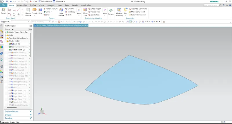
Create the 'offset curve in face' for a distance of 20 mm as shown in the picture. Use fillet sharp corner to ensure that sharp corners are replaced by the best fit fillets (30 mm). Trim the working surface with this offset curve to create the outer flange.
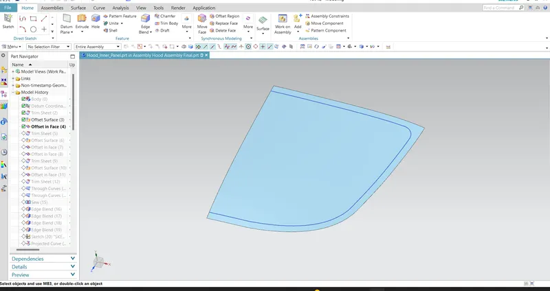
Again offset the working surface to the length of 3.7 mm same as previous one direction and create the offset curve in face to the distance of 22 mm and 35 as mentioned in the master section. Now trim the offset surface with this curve.
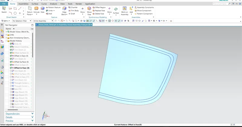
Also, do the same thing for the another offset to a distance of 25 mm. Create the curve in face to a distance of 50 mm and trim the offset with it. Now create the law extension surface by using the edge of this newly created surface.
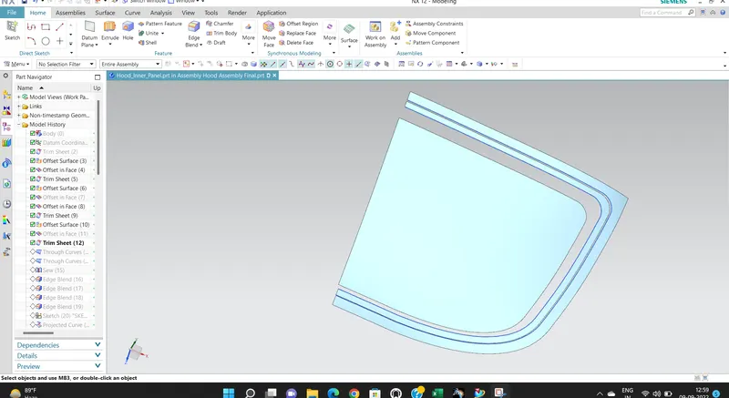
Join both the surface using through curves.
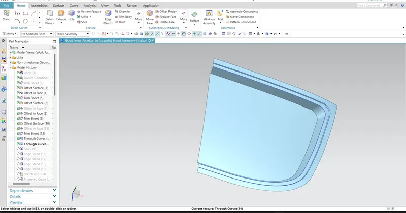
Use face blend and edge blend to create the smooth corners.
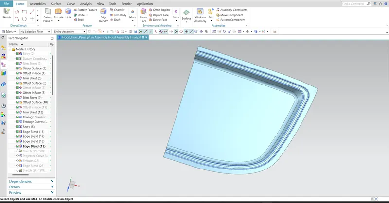
To create the emboss, offset curve in face to 15 mm and use emboss feature to create the emboss shown.
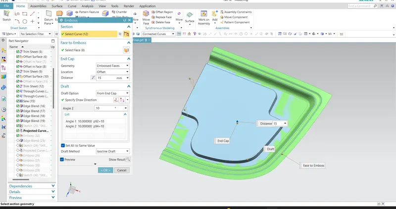
Also create the embosses on the inner panel.
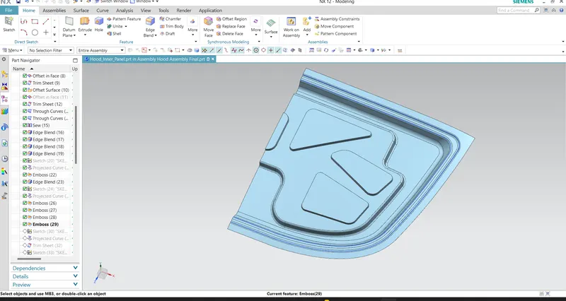
Cut the profiles on the embosses using the trim surface option.
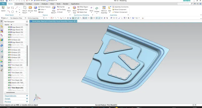
Using wave geometry linker, import the face of the hinge from the assembly work bench to the inner panel part file and create the emboss for that, all sharp edges are blended.
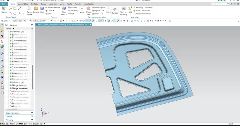
Mirror the sheet and sew them together.
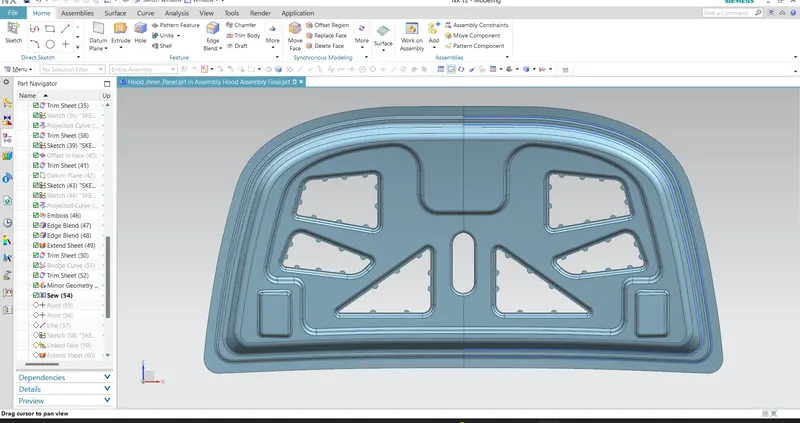
To locate the position the striker, use the circular trajectory formed by the point which betweet the axeses of the hinge.
The circle is drawn at the middle of the hinge axis. The striker pin axis is required to lie on that circle and is its need to perpendicular to the circle segment.
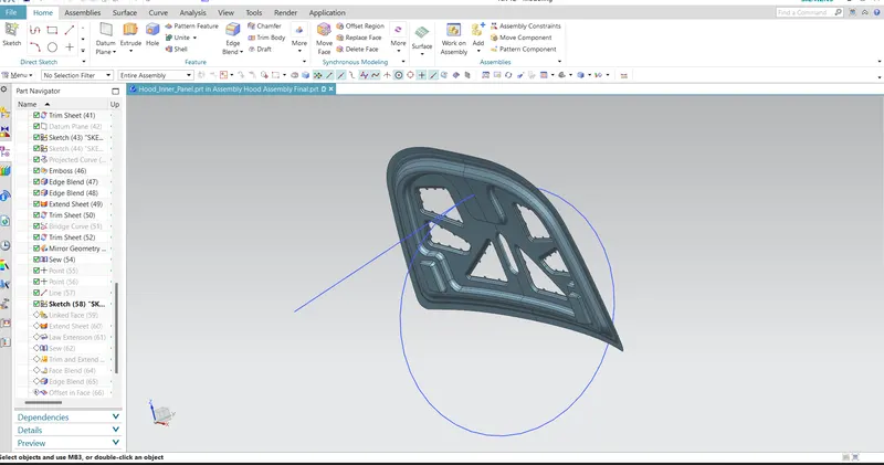
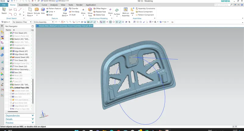
Using wave geometry linker, extract the face of the striker and with reference to the create the emboss on the inner panel.
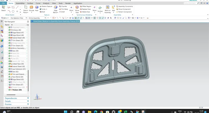
Thicken the sheet to 0.75 mm inner side and apply required edge blends.
Also, create the hem region on the outer panel and thicken it to 0.75 mm.
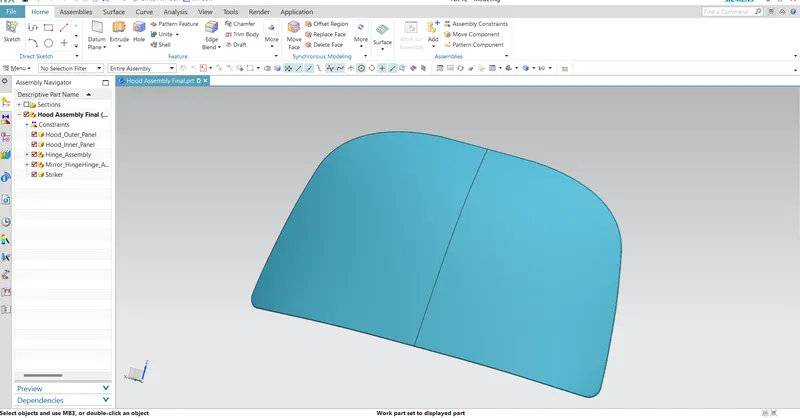
Mirror the hinge assembly and align them with the inner panel. Also striker is positoned.
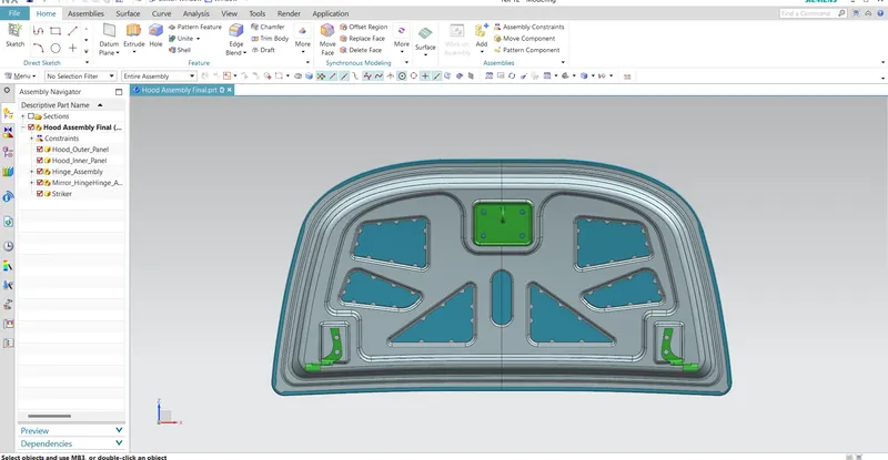
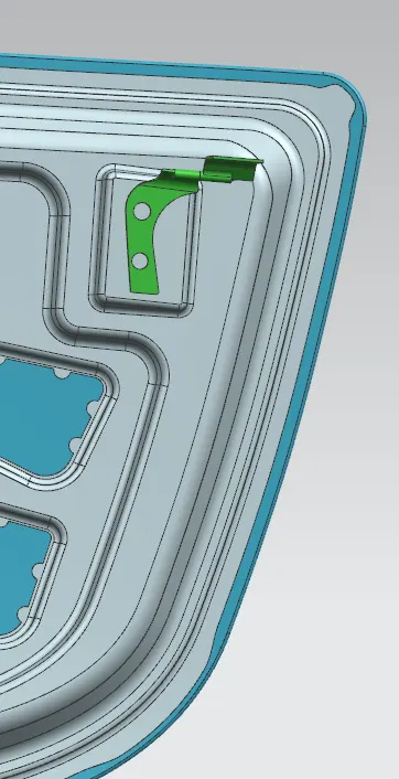
Create the reinforcements with the thickness of 1.5 mm at the hinge points to increase the strenght of the certain region,
HEMMING CROSS-SECTION :
As mentioned, the distance between the inner panel and outer panel is maintained 0.2 mm on both sides.
EDGE RELIEF FOR HEMMING :
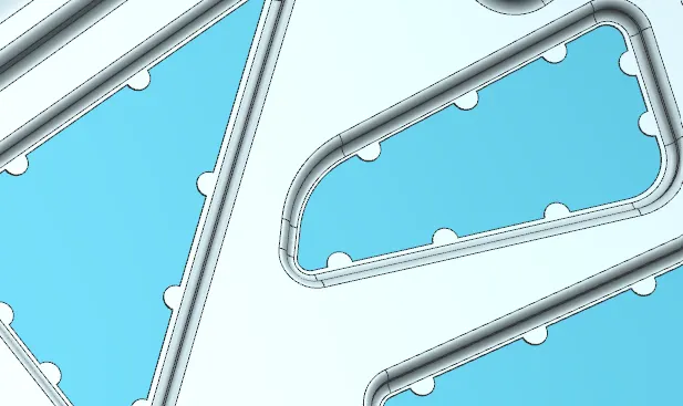
Edge reliefs are given at the corners of the hemming sheet to provide the relaxation edges. This fecilitates the proper interaction of tool with the work.
Also all edge blends are created with minimum of 3 mm + thickness of sheet which is 3.75 mm
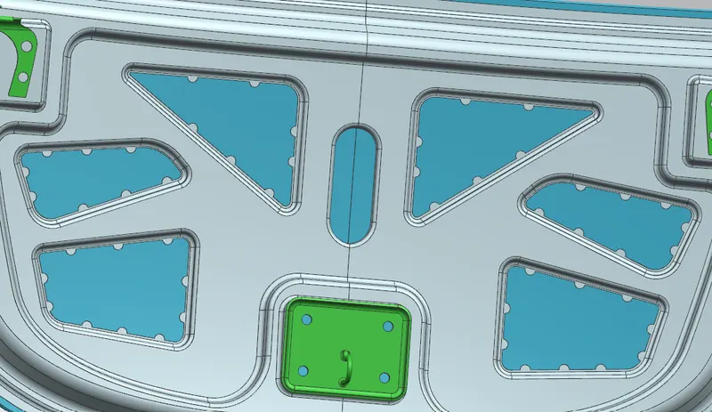
Between the embossed faces, the flat surface is maintained for a distance of atlest 6 mm in all marked areas in the below picture. If this distance is less than 6 mm, this may produce the high stress concentration in that area and leads to the failure of the part.
Also the draft is given to all embossed faces to a minimum of 7 degrees.
MASTIC SEAL :
The mastic sealents can be used for weatherproofing, draught stripping etc. The mastic is sealent is applied in this assembly between the inner panel and outpanel such that the vibration caused are eliminated and reduces the noise and harness (NVH).
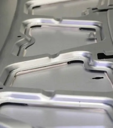
For applied mastic sealant, the distance required between the inner panel and outer panel 5 mm.
Mastic points are created to apply the sealent. The mastic sealant is effective upto 80 diameter from the point of application.
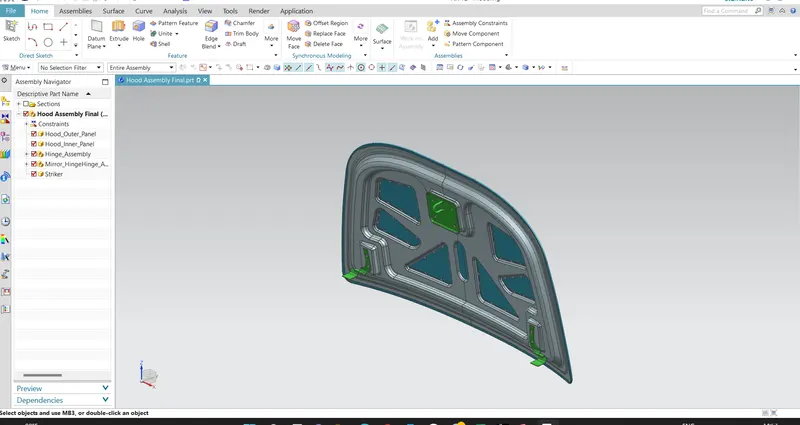
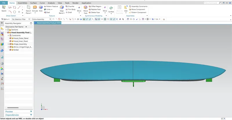
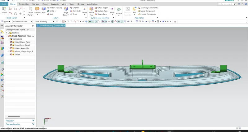
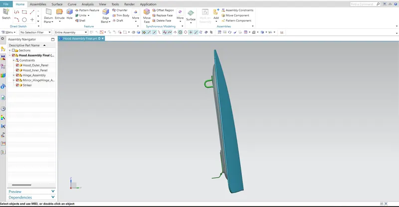
VIEWS :
CONCLUSION :
Finally in this project, we have created the inner panel and outer panel of the car hood with reference to the given Class A surface of the outer panel of the hood. Both the panels are assembled with the help of hemming. Also assembly of the relative components such as hinges, striker and reinforcements is made.
Thus the hood was successfully designed by following the procedures. The model is passed to the CAE team for further analysis for optimizing the design. Hood inner and outer panels are usually manufactured through metal stamping processes. Metal stamping is a manufacturing process used to convert flat metal sheets into specific shapes. It is a complex process that can include a number of metal forming techniques — blanking, punching, bending and piercing, to name a few. Stamping — also called pressing — involves placing flat sheet metal, in either coil or blank form, into a stamping press. In the press, a tool and die surface form the metal into the desired shape. Punching, blanking, bending, coining, embossing, and flanging are all stamping techniques used to shape the metal.