Hood design-Week 2
DESIGN OF HOOD
AIM
create an ASSEMBLY of Hood Inner Panel, Outer Panel, Latch, Hinge and the Reinforcements.
create a report about the Hood Design which includes a details about hood and its components, Latch Trajectory, Mastic Data, Emboss Definitions, Manufacturing process like Deep-Drawing and Hemming, and all the parameters followed in the design.
HOOD
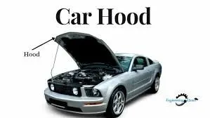
The hood is the hinged cover over the engine of motor vehicles. Hoods can open to allow access to the engine compartment (or trunk on rear-engine and some mid-engine vehicles) for maintenance and repair. In design perspective hood should meet some specific conditions like pedestrian safety, hood head zone for the lock striker, force distribution when subjected to frontal collision (occupant safety), manufacturability etc. A typical hood assembly consist of hood outer panel, inner panel, latch and striker, hinge, hood stay. Hood stay is an apparatus for supporting the engine hood of a motor vehicle in its open position. It is the most critical part of the car as it is always exposed to the frontal crash, climatic conditions, heat generation by the engine compartment, etc. This gives access to the engine, battery, and other components which are always needed to be inspected at regular intervals. The time of inspection could be maintenance, repair or replacement of the parts. Hood is the combination of an outer and inner panel and as per its design consideration, it also dissipates energy outside the car body.
Design consideration
Traffic accidents are terrible scourge that occur in many countries, specially for developing countries where transportation affairs like tangled yarn.Besides functioning as an engine compartment cover, the hood of modern car can also help to manage the impact energy of a pedestrian's head in a vehicle-pedestrian impact. Vehicle safety factors should simultaneously consider occupant and pedestrian safety, given that pedestrians are the third largest category of traffic fatalities. Most pedestrian deaths occur due to traumatic brain injury, resulting from the hard impact of the human head against the vehicle's stiff hood or windshield. Therefore, how to design a pedestrian- friendly vehicle and propose a new hood structure is a matter of urgency for minimising pedestrian head injuries. In this study, three kinds of sandwich hood structures are proposed for reducing pedestrian head injuries, including carbon fibre-reinforced polycarbonate, carbon fibre-reinforced foam and aluminium-reinforced polycarbonate. In assessing the friendliness of vehicle hoods, this study adopts the EEVC/WG17 regulations on head forms for hood tests. The finite element method is used to simulate the impact between the vehicle's hood and the headform impactor. The software used in simulation is LS-DYNA. The results predicted by the headform-hood tests show that the hood structure with aluminium-reinforced polycarbonate material provides enough absorption capability to protect pedestrians from the impacts of accidents. It is also stiff enough to keep pedestrians' heads away from the inner parts of the engine cavity .
Euro NAP
Euro NAP the European car assessment program is European car safety performance assessment program based in Leuven and founded in 1997. They published safety reports on new cars and awards star ratings based on the performance of the vehicle in a variety of crash test including front side and pole impacts and impacts with pedestrian. The top rating is 5 star So here in Hood we separate the whole area of hood into several small part / region during frontal crash. Hood is the major portion a person is gonna come in contact with. So Euro NCAP specified some guidelines under which we distribute hood region into several parts and try to get more green region.
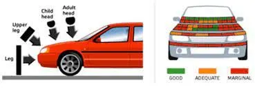
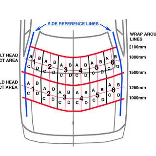
This region is basically distributed in relation to the height of children and adults who come in contact from front while accident. So, here the main motto is to achieve more green region and for that we provide splits in embosses so that during head impact the consequences of collision come less effective. So here I have given splits accordingly to improve head impact zone effectiveness in providing less damage to the person who hit it.
Wrap Around Distance (WAD)
When a car crashes on the pedestrian, the whole human body wraps around the front shape of the car and the head impacts on the bonnet or the windscreen. The distance on which the head impacts on the car from the ground is called as the Wrap Around Distance (WAD). To be specific the Wrap Around Distance is a measurement of distance from the ground to the head impact zone over the outer surface of the car. The wrap around distance is measured longitudinally in the center of the vehicle from the ground.
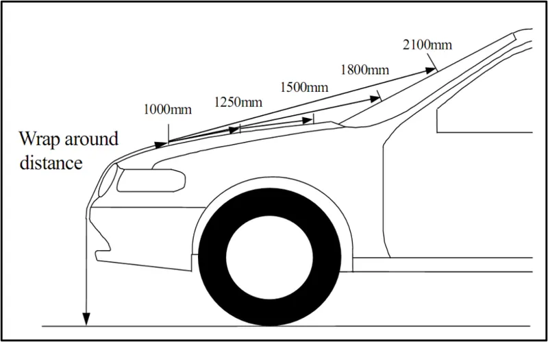
The severity of the injury caused by the frontal crash depends on the type and shape of the vehicle, speed of the vehicle and the movement of the pedestrian relative to the vehicle. In addition to these parameters, the wrap around distance plays a major role in the safety measurement of a pedestrian. During the crash analysis, based on the Wrap Around Distance(WAD), two test areas will be created namely Child head impact zone and the Adult head impact zone. The child head impact zone is between 1000 to 1700 mm WAD and the adult head impact zone ranges between 1700 to 2100 mm WAD
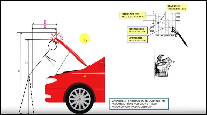
Head Clearance criteria:
Head clearance is decided upon the zone or country. So same car if it is made for different country will have different opening angle depending on the country or region. The distance C and D shown in the image is represented as graph in the upper right corner of the image. Choosing the right head zone position will decide upon the angle of the hood opening. Product engineers will also get input from the marketing team for deciding head zone.
Hood support Rod and Gas Stay
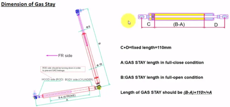
There are two types of support is there, Gas stay and Support rod
1.Gas stay
spring stays are designed to be used on upward lifting doors, once you have opened the door slightly the spring will push the door to the fully open position, Euro fit stock various size springs depending on the door size requirements. This is mostly used for where the car bonnet weight is heavy.Struts contain nitrogen gas under pressure and some oil to damp movement and to lubricate the seals.
Support Rod
Support rod is basically long cylindrical rod. It safely keep an engine hood in an open state even if external forces are abruptly generated due to vibration & wind.It is Cost effective ansd Simple. the disadvantage is that When striking with the automotive body panel it leaves scars which are very likely to cause rust. The metal rod is often too hot to be gripped by hand when one attempts to keep the engine hood open for inspecting the engine room immediately after the vehicle has been stopped.
Design consideration of support rod
When hood is closed, during that the support rod will stay in place & positioned where it gets enough clearance to lay down & doesn't hit & create rattling noise while motionSupport rod will always be placed opposite side of the battery’s position. So that it doesn't interfere with rod. If battery is kept at left hand side then support rod will be placed at RHS. Now a straight support rod could wobble as the weight it is going to support would be around 8 to 9 kg. So a little deflection will be given in rod and design engineer has freedom to give it anywhere along the rod but the deflection shouldn't be more than 35 mm.
Manufacturing methods
Deep Drawing
Deep drawing is one of the most widely used processes in sheet metal forming. Apart from its use in many other sectors, it is applied in the automotive industry for the manufacturing of car body parts. The deep drawing process is a forming process which occurs under a combination of tensile and compressive conditions. A flat sheet metal blank is formed into a hollow body open on one side or a hollow body is formed into a hollow body with a smaller cross-section. Deep drawing processes are divided into three types:
Deep drawing with tools
Deep drawing with active means
Deep drawing with active energy
In the automotive industry, deep drawing is usually carried out using rigid tools.
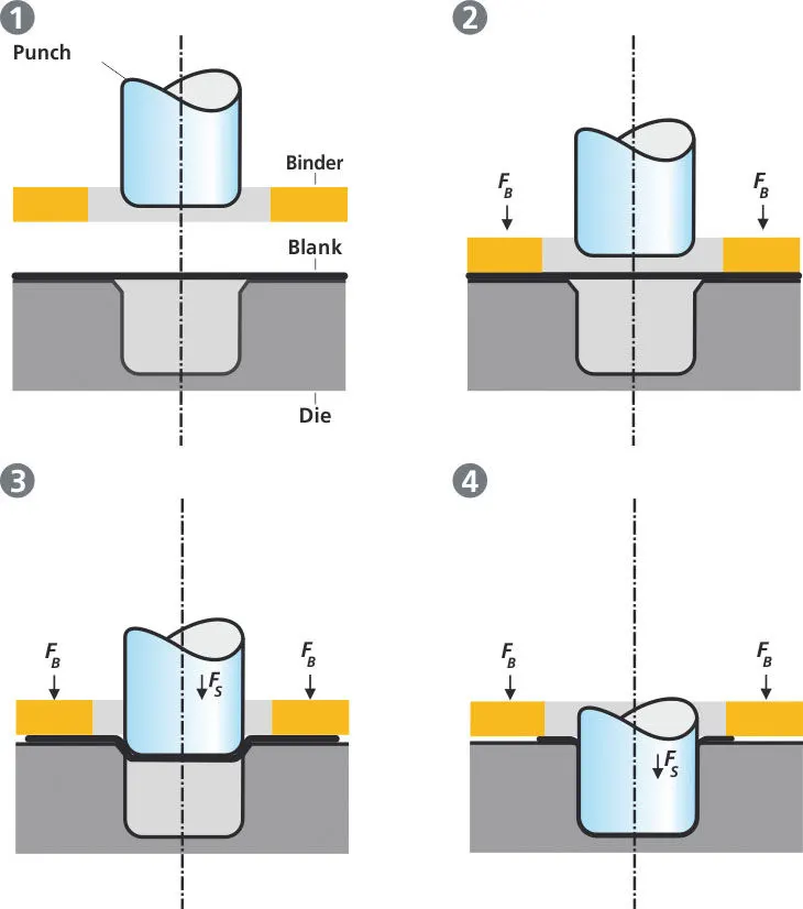
The figure illustrates the deep drawing process. The rigid tools consist of a punch, die and binder. In deep drawing, the plate holder closes after the metal sheet blank has been inserted. Next the sheet is clamped between the die and the binder. This process slows down the flow of the sheet while it is being drawn and thereby prevents wrinkles from forming under the binder. The punch stretches the sheet over the die radius and forms it in the die. The amount of punch force necessary for forming is thereby continually increased up to the lower dead center of the punch. Whereas in pure deep drawing there is no reduction of sheet metal thickness, forming is achieved in stretch forming purely as a result of a decrease in sheet metal thickness. Stretch forming is extensively used for the forming of only slightly curved parts with low depth of draw (e.g. roofs, doors). When drawing complex car body parts in practice, there is usually a combination of stretch and deep drawing involved. It is necessary that the sheet metal is stretched as well as possible without reaching the material's limits (e.g. splits, wrinkles). There are approximately 300 to 400 sheet metal parts which fit together to form the body of a car. In order to manufacture high quality sheet metal parts optimally for their particular use, specialized software simulates the complete deep drawing process.
spring back Effect: Springback is the geometric change made to a part at the end of the forming process when the part has been released from the forces of the forming tool. Upon completion of sheet metal forming, deep-drawn and stretch-drawn parts spring back and thereby affect the dimensional accuracy of a finished part. Through the application of new materials, the number of problems increases. Forming parts made of these materials are more affected by springback than parts made from conventional deep-drawn steel. Concerning classic sheet metal defects such as splits and wrinkles, strain in the sheet metal is decisive. If springback occurs, such models are not enough to predict a deformation. In this case, the stresses are decisive and a considerably higher accuracy is crucial. During the development of tools, springback is compensated by software in order to remove the part from the tool straight away in the required dimensions. Intense tryout loops, which occur at a very late stage in the development of the tool, are reduced to a minimum. Simulation software can not only detect springback early on, it can also compensate for it. In this way, tooling processes are improved and manufacturing costs are significantly decreased.
Hemming
Hemming is a forming operation in which the edges of the sheet are folded or folded over another part in order to achieve a tight fit. Normally hemming operations are used to connect parts together, to improve the appearance of a part and to reinforce part edges.
In car part production, hemming is used in assembly as a secondary operation after deep drawing, trimming and flanging operations to join two sheet metal parts (outer and inner) together. Typical parts for this type of assembly are hoods, doors, trunk lids and fenders.
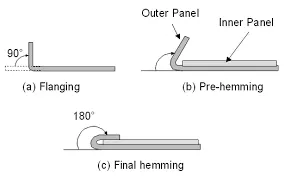
The accuracy of the hemming operation is very important since it affects the appearance of the surface and surface quality. Material deformations, which occur during the hemming process, can lead to dimensional variations and other defects in parts. Typical hemming defects are splits or wrinkles in the flange, material overlaps in the corner areas or material roll-in. This is why it is important to use simulation tools in order to, on the one hand, better understand the hemming process and, on the other hand, significantly reduce the number of “trial and error” loops during tryout und production.
Hems are folds to the edge of a part to create a rounded, safe edge. Hems may be open, flat, or tear-dropped, and tolerances depend on the hem’s radius, material thickness, and features near the hem. The process of creating hems is called hemming.
Hems are created by bending a flange of your part back on itself. This increases the strength of the hemmed edge and also gets rid of any sharp edges, which your technicians (and possibly your future self) will thank you for. The downside (drawback) of hems is that they’re expensive (they usually take three bend operations to form) and add weight to your part.
Types of Hems & their design Constraints :
Generally a hem has a round feature and a return flange. Based upon the nature of these two there are various types of hems. We will be looking each one by one below.
1] Open Hem -
As said earlier a Hem has a full round feature and a return flange. In the Open type Hem, bend angle is equal to 180 degrees.
It is recommended that the ratio of the open hem radius to the sheet metal thickness should be greater than or equal 0.5. Also, the ratio of return flange height to the sheet metal thickness should be greater than or equal to 4. For open hems, the minimum inside diameter is equal to the material thickness (larger diameters tend to lose circular shape), and the return length is at least 4 times the material’s thickness.
2] Rolled Hem -
In the case of Rolled Hems there is no return flange available. Here the only design criterias are available for bend radius of hems.
It is recommended that the ratio of the external radius of a rolled hem [R] to material thickness[t] should be greater than or equal to 2.
Also, the ratio of the rolled hem opening [D] to material thickness [t] should be greater than or equal to 1.
3] Tear Drop Hem -
In tear drop hem the bend angle is greater than 180 degrees. It is recommended to consider the following guidelines while designing a tear drop hem -
i) The ratio of the radius of a tear drop hem to the sheet metal thickness should be greater than or equal to 0.5
ii) The ratio of the return flange height to the sheet metal thickness should be greater than or equal to 4.0
iii) The ratio of the hem opening (spacing between the hem edge and the part) to the sheet metal thickness should be greater than or equal to 0.25
3] Closed Hem -
Hems without any inside radius are called Closed Hem. Closed hems are not recommended if the hem geometry is to be painted or if the material used is SST or Aluminum. In closed hems, return flange length from outside the bend should be equal to or greater than four times the material thickness. Generally Closed hems tend to fracture at the bend and cause entrapment of solutions during the finishing process. So one should try to avoid using those in their design until its design requirement.
There are various types of hemming operations:
- Conventional die hemming
- Roll hemming
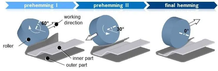
Conventional die hemming
Conventional die hemming is suitable for mass production. In die hemming, the flange is folded over the entire length with a hemming tool. Normally the actual hemming is a result of a forming operation in which the flange is formed with a hemming tool after the drawing and trimming operations have been completed. The formed flange is then hemmed in several process steps. These steps include, for example, the pre-hemming and final hemming depending on the respective opening angle of the flange. Production plants for conventional die hemming are very expensive, but the cycle times are very low.
Roll hemming
Roll hemming is carried out incrementally with a hemming roller. An industrial robot guides the hemming roller and forms the flange. Roll hemming operation can also be divided into several pre-hemming and final hemming process steps. Roll hemming is very flexible to use and tool costs are significantly lower as compared to those of conventional die hemming. However, the cycle times are much higher since the hemming is realized using a hemming roller which follows a defined path.
Hood components
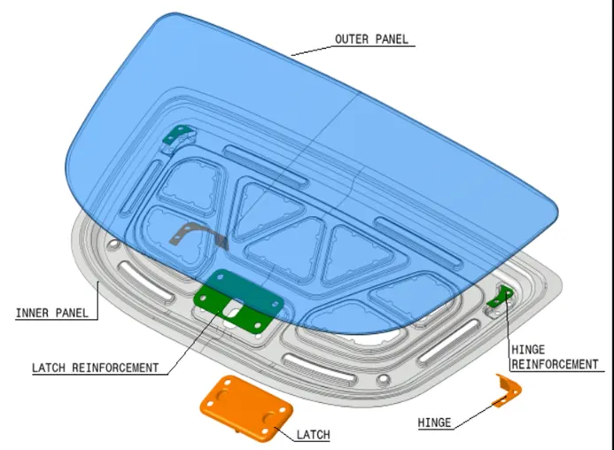
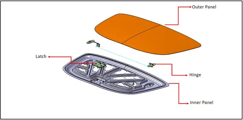
Hood mainly consist of 4 components:
Inner panel, Outer panel, Hinges and Latch striker.
Hood outer panel :
Design of outer panel is mainly inspired by aesthetic but there is some engineering also to it. Here main purpose of outer panel is to cover the inner panel to provide aesthetic look at the same time Panel must be curve & sleek so that it behave aerodynamically and air hitting from front reflect from it efficiently. So here rather than using seam and spot welding we use hemming method to join outer and inner panel. Hemming is a type of folding or wrap-around process in which roller bend and press the extrapolated flange in a way that it holds the inner panel firmly, then a sealant is also provided in between them under folds to get water tightening. While hemming we provide relief around corner as it helps in easy hemming or undistorted hemming while roller took turn around any corner. It's thickness is also 0.75 mm maximum
Hood inner panel :
Inner panel is the part that gives strength and rigidity to the outer panel. The master section represents the initial emboss shape and size. Then we provide the emboss for the latch and hinge elements after fixing the location.
Reinforcement :
Reinforcements are provided according to the design requirements. Mainly it is provided at the hinge and latch regions to improve the strength locally. Usually thickness of reinforcements will be higher than that of the inner panels and the value varies according to cost and requirement. According to the design requirement here it is given 1.5mm thickness to both hinge and latch reinforcements.
Hinge -
Hinge is used as a controlling element for opening & closing of the hood. It connects the hood & engine compartment of car. The hood's hinges serve one other purpose besides holding the hood-safety. In case the hood latch should fail, the hinges are there to keep the hood attached to your car. Otherwise, if you were traveling at high speeds and the latch fails, the hood could break from the damaged hinges and cause disaster and injury.Actually, even if only one hood hinge fails, a strong slipstream can topple the hood and hammer it against the windshield.
• Allows hood to open and close without losing alignment
• Holds hood down in case of a collision
• Provides a direct fit
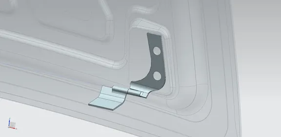
hinge reinforcement:
Hinge is a mechanical bearing that connects two solid objects typically allowing only a limited angle of rotation between them it has one degree of freedom. So here hinge is providing rotation to hood about it's own axis and also keep it connected to the fender portion. So while creating space for hinge we need to provide emboss there, because of emboss and hole its strength got affected so to compensate that we provide hinge reinforcement. Hinge reinforcement has thickness around 1 to 1.5 mm to provide reinforcement to hinge embossed region.
Latch striker:
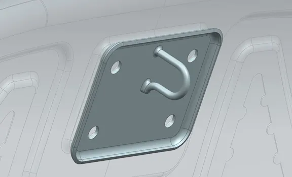
which is placed over the hood & get attached to the hole provided in engine compartment. thus it is used for locking purpose of hood with engine compartment.
Trajectory for Hood opening and Closing:
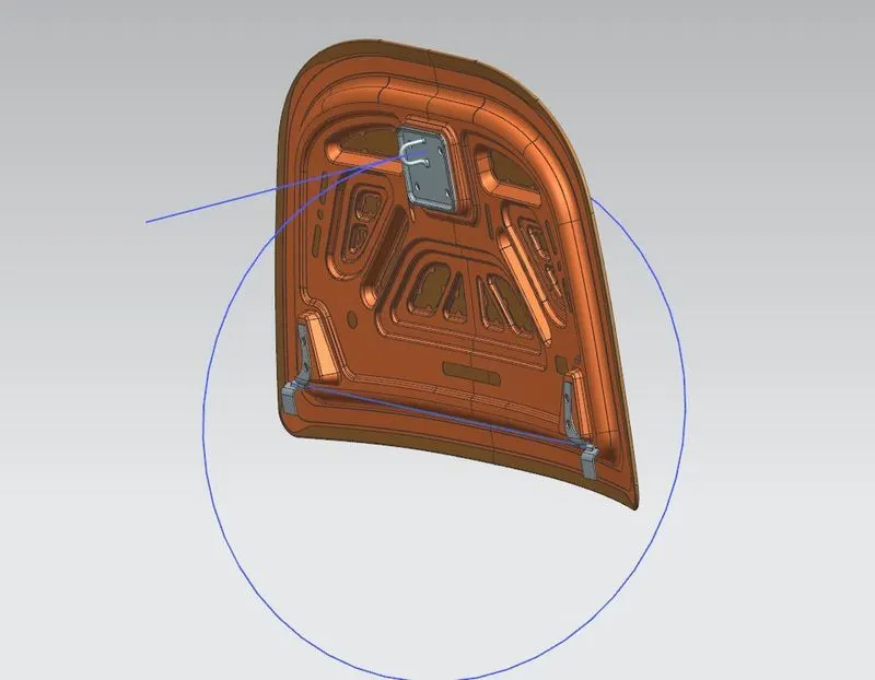
For the proper opening and closing of the hood, the striker should be positioned at a correct position. The striker should be perpendicular to the trajectory of the hood. The flanges are positioned at their respective positions. Then the line is drawn at a straight. Now the trajectory is derived from the hinge axis and the center distance from the striker. It is denoted using the circle. Latch trajectory is given by the circle drawn from the hinge axis point. Hinge axis point is the centre point of the hinge axis. First, we can fix either the latch or the hinge. If we have fixed the hinge position then we should plot the Trajectory circle for the latch. For proper mating condition the striker axis through the tip of the striker should be tangential to the latch trajectory.
Emboss:
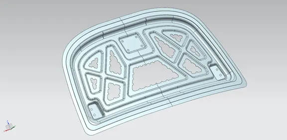
We provide different embosses throughout the inner panel. We can increase the stiffness of the inner panel through these embosses. The shape and size of the embosses also determines the direction of the force distribution resulted from frontal collision. The force should be always distributed away from the passengers. Here in the figure the embosses are designed in such a way that the force is directed to either sides of the car. Embosses has been given to create extra strength in inner panel and embosses design needs to be inspired by force dissipation phenomena like here I have made embosses in a way if any object hit from front most of the force will get dissipated by its design towards the upper left & right corner so that less force reach at occupants end. Some split or cut is given on embosses to reduce head impact result.
Mastic Sealant Data :
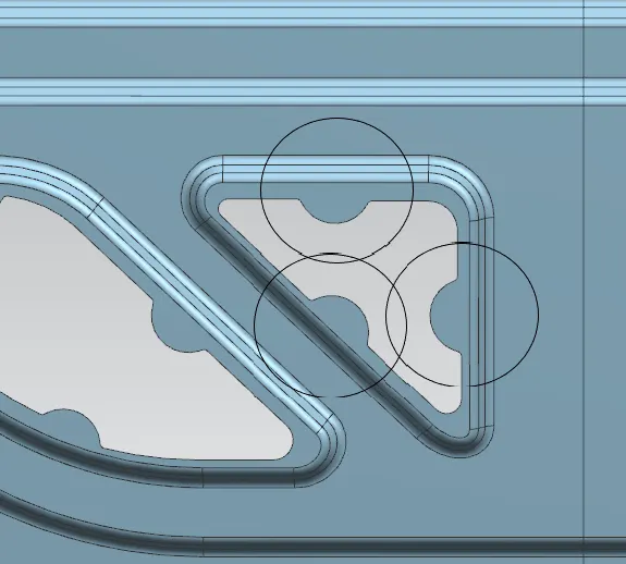
Hood commonly possess large surface area and hemming can only be provided through its boundary. We cannot use other joining techniques like welding, riveting etc because they leave marks on the outer panel which spoil its aesthetic appearance. So, mastic sealants are used to stick the inner surfaces of outer panel and inner panel. Mastic sealants are elastic compound that behave like rubber. It is applied between the inner and outer panels at specified spots. Each spot of mastic sealants has its effect around a circular region of 80mm diameter. Thus, the mastic points are arranged in such a way that it covers the areas away from the hemming which are more vulnerable to vibrate.
Mastic data:
It is basically an NVH topic mastics are point / surfaces given on embosses for applying mastic sealant to join outer and inner panel and also give good value of NVH. So mastic sealants are joining material used to join inner and Outer panel and at the same time reduces the NVH value. One spot of mastic sealant provides strength locally at around 80 mm so we need to put these mastic points in such a way that it covers the most of the hood region except reinforcement are of latch and hinge because that alone provide good NVH so no worries there. Here I have spotted points where I have applied mastic data when mastic sealant will be applied and while undergoing hot bath it gets hardened & make the joint strong. designing inner panel one must take care of spaces to provide on panel for latch and hinge.
conclusion
the assembly of hood is designed using the given data such as the outer skin data hinge and latch the thickness of panel and reinforcement
outer panel is created using skin data and the hemming is provided using the given data
the inner panel is created from the skin data . emboss and space for mastic seal is created. reinforcement is provide.the latch striker and hinge mounted on inner panel