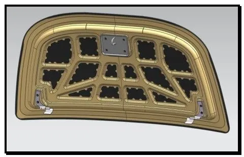
Hood design-Week 2
AUTOMOBILE HOOD
The hood or bonnet is the hinged cover over the engine of motor vehicles. Hoods can open to allow access to the engine compartment, or trunk on rear-engine and some mid-engine vehicles) for maintenance and repair.
Hoods are usually made from the same material as the rest of the body. This can be steel, aluminium, fiberglass, or carbon fibre. However, some aftermarket companies produce fiberglass or carbon fibre steel hood replacements to make the vehicle lighter.
The hood release system is common on most vehicles and typically consists of an inner hood latch/lock handle, a hood release cable, and a hood lock assembly. The hood lock handle is usually located under the steering wheel, next to the driver’s seat, or in the door frame.
COMPONENTS OF HOOD
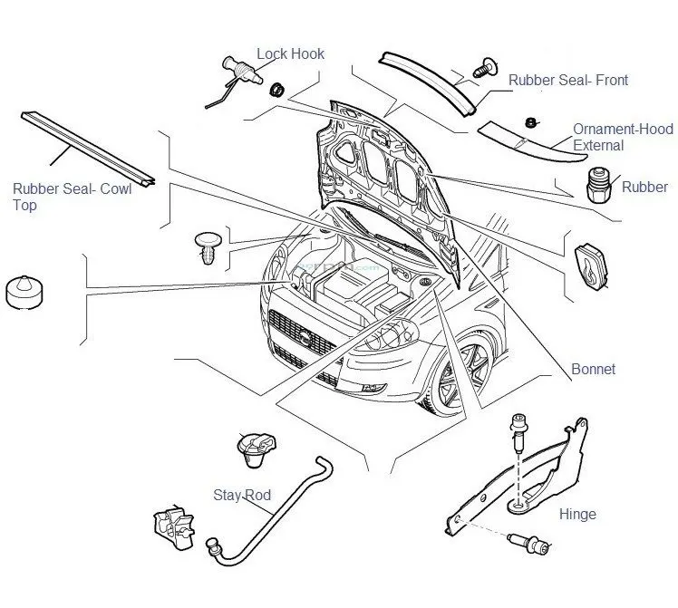
The major components of car hood, are as follows: -
1.) Hood Outer Panel.
2.) Hood Inner Panel.
3.) Hinges for opening and closing of Hood.
4.) Striker for the locking mechanism of hood during closed condition.
5.) Hood Support System.
1.) HOOD OUTER PANEL
Hood Outer Panel is the external skin of the hood. Hood Outer panel covers the engine, radiator, Battery and Transmission system. Outer Panel is a single piece metal sheet component.
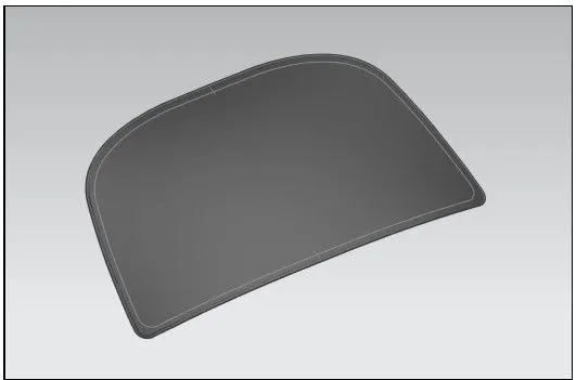
The outer panel is the first part of the hood, followed by the internal structure comprising of inner panel. The outer panel is the body of hood and inner panel forms the skeletal system.
2.) HOOD INNER PANEL
The Hood Inner Panel is extracted from the Outer Panel. The inner panel forms the major part supporting the outer panel, in terms of strength of the hood. The inner panel plays an important role in terms of design, as it helps to protect the under part, with minimum damage during an crash/accident met by an obstacle.
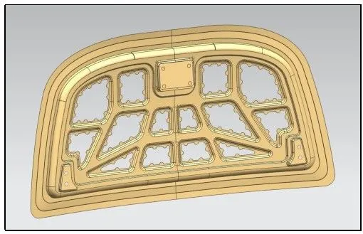
3.)HINGES FOR OPENING AND CLOSING OF HOOD.
Hinge assembly is an assembly similar to door hinge in house. The main purpose of the hinge is to rotate the part in a given angle to serve the suitable purpose. In the Hood design, the placement of hinge assembly plays an important role, for making the hood to actuate at certain angle.
The Center axis line of the two sub-parts of hinge assembly should lie in a single line, for making the hinge to rotate at a common axis.
A line is drawn from the centre of the axis of a hinge assembly at one end of the inner panel to the similar hinge assembly at the opposite end of the inner panel, in order to make the centre axis of both the hinge assembly to lie on same line.
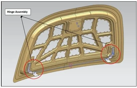
1.) STRIKER FOR THE LOCKING MECHANISM OF HOOD DURING CLOSED CONDITION.
Striker is the part present in the inner panel of the hood assembly at the top end, in the middle of two hinge assemblies facing opposite to the hood outer panel.
The main function of the Striker is to perform the locking mechanism, during closing of the hood/bonnet.
The Striker comes with a U-Shaped lock attached to a plate, which engages with latchet at the closing section of the bonnet.
The placement of the striker in the hood inner panel, is done by drawing a circle at a plane present in the middle of the hood inner panel, facing perpendicular to the center line axis of the hinge assembly.
After drawing the circle, a tangent is drawn perpendicular to the direction of striker placement, in order to obtain the exact alignment.
Based on the line drawn, the striker is placed and fixed to the inner panel.
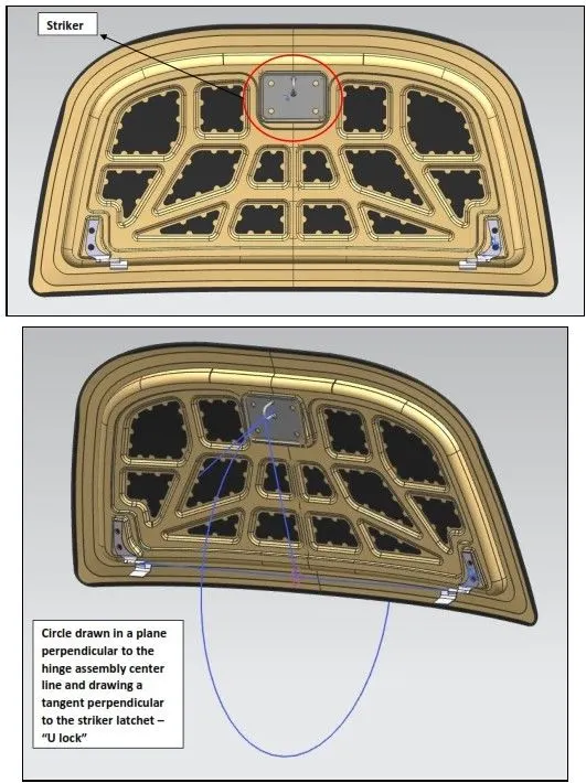
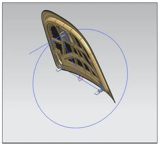
5.) HOOD SUPPORT SYSTEM
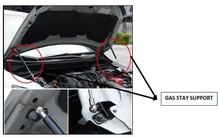
Hood Support system is nothing but the Hood Stay being an internal part present at the side of the engine compartment of a car, which is used to support the hood during the opened position.
There are two type of Hood Stay as follows,
- Support rod System.
Support Rod System is a simple rod, provided with a certain bending in accordance to its resting position to the side of the engine compartment.
The one end of the Support rod system acts as a hinge, and the other end has a hook, which engages to the lock, present in the hood inner panel.
The Support rod system supports the entire hood, by taking the load during the open condition of hood.
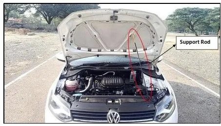
2. Gas Stay System.
Gas Stay System is a advanced type of supporting system, which has a linear actuating device, used to control the motion of the hood, while opening and closing.
The actuating device is linearly driven by gas.
Most of the vehicles have two linear actuators, for making the hood stay at open position more firmly, with less vibrations during the flow of wind.
DESIGN ANALYSIS FOR HOOD
The design is based on the criteria of the opening angle of hood. The Opening angle of the hood varies from one country to another country, based on the average height of the individuals present in a given population.
The Hood Inner Panel forms the main reinforcement, to provide strength to the hood outer panel. The Design of the hood inner panel, should be such that, when the obstacle/pedestrian crashes to the front part of the hood outer panel, the impact should be distributed on sideways, so that the damage on engine is minimised.
There should be proper cut-outs and aligned inner structure in hood inner panel, so that the counter impact absorbed by the pedestrian is less, thus leading to minimized injury.
- Important considerations for designing the Hooda.) WAD – Wrap Around Distance
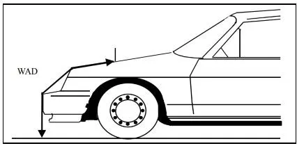
WAD (Wrap-Around Distance) is the geometrically traced distance from the contact point with the Ground Reference Plane, vertically below the front face of the bumper, to any point on the vehicle front structure.
b.)NVH – Noise, Vibration and Harshness
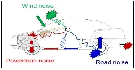
Noise, vibration, and harshness (NVH), also known as noise and vibration (N&V), is the study and modification of the noise and vibration characteristics of vehicles, particularly cars and trucks. While noise and vibration can be readily measured, harshness is a subjective quality, and is measured either via jury evaluations, or with analytical tools that can provide results reflecting human subjective impressions.
- MASTIC DATA
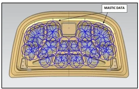
Mastic is commonly used as an adhesive and sealant, to join two surfaces. In designing the Hood Inner Panel, there are small points are created near the cut-outs of inner panel structure, where the mastic sealant is applied.
In joining of the hood outer panel and hood inner panel surface, joining process like – spot welding is not suitable. Hence, Mastic sealant are applied to joint the two surfaces.
The Mastic Data is created by drawing a circle of 80mm Diameter at the centre of the semi-circle points near the cut-outs in hood inner panel.
- EMBOSSING IN HOOD INNER PANEL
Sheet metal embossing is a stamping process for producing raised or sunken designs or relief in sheet metal. This process can be made by means of matched male and female roller dies, or by-passing sheet or a strip of metal between rolls of the desired pattern.
The metal sheet embossing operation is commonly accomplished with a combination of heat and pressure on the sheet metal, depending on what type of embossing is required. Theoretically, with any of these procedures, the metal thickness is changed in its composition.
Metal sheet is drawn through the male and female roller dies, producing a pattern or design on the metal sheet. Depending on the roller dies used, different patterns can be produced on the metal sheet. The pressure and a combination of heat actually "irons" while raising the level of the image higher than the substrate to make it smooth. The term "impressing" refers to an image lowered into the surface of a material, in distinction to an image raised out of the surface of a material.
In most of the pressure embossing operation machines, the upper roll blocks are stationary, while the bottom roll blocks are movable. The pressure with which the bottom roll is raised is referred to as the tonnage capacity.
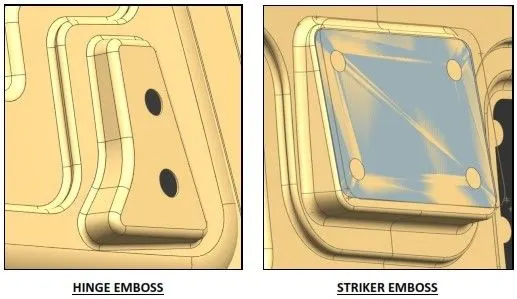
The Embossing in the Hood inner panel is done for Hinges and the Striker, for its placement during Hood assembly process.
- REINFORCEMENTS
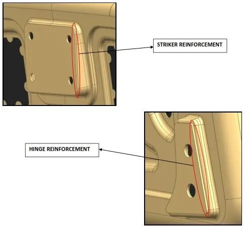
Reinforcements are added in the region of striker and hinge assembly placements in the Hood Inner Panel.
When the Striker and hinge assembly are assembled in their respective sections of hood inner panel, then the area of that place, occupied by the striker and hinge assembly experiences a loss in strength.
In order to compensate the loss of strength, respective reinforcements are added to nullify the loss.
Reinforcements are additionally given to compensate the loss, which happens on that area locally, intentionally given to improve the strength on that particular area locally.
- DEEP DRAWING
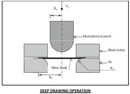
Deep drawing is a sheet metal forming process in which a sheet metal blank is radially drawn into a forming die by the mechanical action of a punch. It is thus a shape transformation process with material retention.
The following list includes the five stages of development for deep drawing process in sheet metal: -
- Punching the Metal Sheet
Deep drawing processes begin when the punch hits the metal sheet for the first time. Previous to the first hit, you need to place the sheet on the machine handling the task. You also need to make sure that the punch is in the right place, and the right pattern for fabrication has been programmed. Make sure that the equipment does not vibrate with a hit. That could harm the finished product.
- Bending the Sheet
There should be an initial application of force on the sheet. This first hit should bend the contour of the die cavity. As the bending process goes on, the strength applied on the sheet should never exceed the amount of pressure applied to the metal being pressed. That way, we can avoid wrinkles on the metal sheet.
- Straighten the Work
The next step is to increase the force applied to bend the sheet on the blank. By doing this, we will straighten out the metal without breaking it. During this procedure, we will sink the annular punch-die clearance. When we straighten out a metal sheet, we get shorter vertical walls. This is also a process that allows us to see how much we can actually extend metal sheets to get what we need.
- Friction and Compression
On this stage, the blank will flow following a radius pattern as friction works to do the rest. These frictional forces will act on the lower surface of the piece as well as the upper part of the die. Frictional forces will slowly decrease as the metal sheet moves along the surface of the die. After the friction passes, the blank will show compression, and it will shrink to a smaller size than the die.
- Releasing Tension
In the last stage of this sheet metal manufacturing technique, all of the stress of the piece is released. The blank has to fit in the die cavity creating a vertical wall. The remaining blank takes the shape of a small flange, and the new piece will be treated with uniaxial tension to be ejected.
- HEMMING
Hemming is a forming operation in which the edges of the sheet are folded or folded over another part in order to achieve a tight fit. Normally hemming operations are used to connect parts together, to improve the appearance of a part and to reinforce part edges.
In Vehicle part production, hemming is used in assembly as a secondary operation after deep drawing, trimming and flanging operations to join two sheet metal parts (outer and inner) together. Typical parts for this type of assembly are hoods, doors, trunk lids and fenders.
There are various types of hemming operations:
- Conventional die Hemming.
- Roll Hemming.
- Conventional die hemming
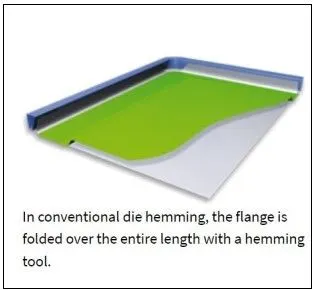
Conventional die hemming is suitable for mass production. In die hemming, the flange is folded over the entire length with a hemming tool. Normally the actual hemming is a result of a forming operation in which the flange is formed with a hemming tool after the drawing and trimming operations have been completed.
The formed flange is then hemmed in several process steps. These steps include, for example, the pre-hemming and final hemming depending on the respective opening angle of the flange.
Production plants for conventional die hemming are very expensive, but the cycle times are very low.
- Roll hemming
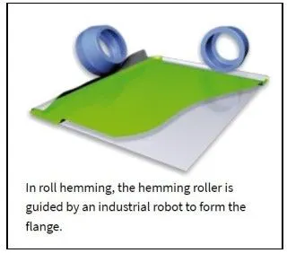
Roll hemming is carried out incrementally with a hemming roller. An industrial robot guides the hemming roller and forms the flange.
Roll hemming operation can also be divided into several pre-hemming and final hemming process steps.
Roll hemming is very flexible to use and tool costs are significantly lower as compared to those of conventional die hemming. However, the cycle times are much higher since the hemming is realized using a hemming roller which follows a defined path.
- HOOD DESIGN FINAL ASSEMBLY
The Final assembly of Hood, comprising of Hood Outer Panel, Hood Inner Panel, Hinge Assembly and Striker have been assembled using the necessary assembly constraints, as shown in the below figure,